Get in touch with Zhenling Company

Types of Milling Cutters: A Feature-Based Guide
We provide more than a long list of milling cutter names. The guide follows a simple path from the feature on your drawing to candidate cutting tools, access checks and the evidence required before approving a production process.
Security & NDA
Your drawings are used for initial review; confirm any confidentiality or NDA requirements before detailed files are exchanged.
Process Specifications
-
Review & Quotation
Engineer-reviewed quotation timing confirmed after drawing review
-
Prototyping & Shipping
Prototype parts ship after drawing approval and process review; timing is confirmed in the quotation
-
Supported Formats
STEP, IGES and PDF files may be included with the inquiry
Cutter Families at a Glance
Milling cutters are often described by tool type and family name. A milling cutter removes material with one or more cutting edges as it follows a programmed path. The family name alone is therefore an incomplete specification.

Broad open faces
Face mills and flat-end toolpaths enter the shortlist, subject to coverage, edges and spindle load.
Pockets and walls
Square, corner-radius or ball end mills can address floors, sides and blended surfaces.
Slots and narrow forms
Slot milling cutters, side-and-face cutters, T-slot cutters and keyseat cutters target constrained geometry.
Dedicated forms
Thread mills, gear cutters, angle milling cutters, hollow mills and corner-rounding tools create specific features.
The Cutter-Feature Evidence Board
Flat lists mix different questions. The board separates function, end geometry, mounting and construction so an engineer can describe the same milling tool without treating those labels as interchangeable.
1
Function or feature
- Face
- Slot
- Thread
- Gear or form
2
End geometry
- Square end
- Ball end
- Corner radius
- Chamfer
3
Mounting
- Shank type
- Bore or arbor type
- Holder interface
- Reach and clearance
4
Construction
- Solid tool
- Tipped tool
- Indexable cutter
- Replaceable insert
ISO 11529:2013 identifies a designation scope for shank-type and bore-type milling cutters in solid, tipped and indexable designs. The standard is a terminology reference; it does not select a cutter for a part.[1]
Reading a cutter description.
The risk is a false one-to-one match because feature access, holder clearance and setup can disqualify the label. NIST frames planning around machining operations and tool requirements, while ISO 11529 provides a naming scope rather than a process approval.[2] The type of cutter and tool geometry state different layers, and cutters are also described by direction, helix and insert style.
Material, Chip Evacuation and Cutting Edges
Even within one tool family, an end mill must match the workpiece material, chip form, available flute space and planned engagement. Two otherwise similar end mills can behave differently in a full-width slot, where chips have limited room to escape.
Material response
Hardness, abrasiveness, heat behavior and chip shape change the cutting process.
Tool and setup response
Tool material, coating, flute count, coolant path, engagement and holder rigidity are reviewed together.
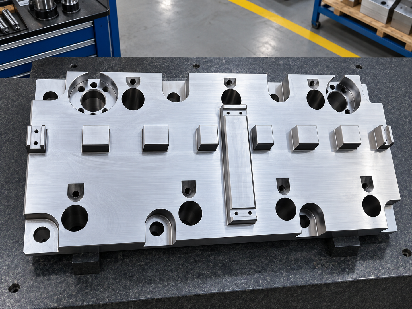
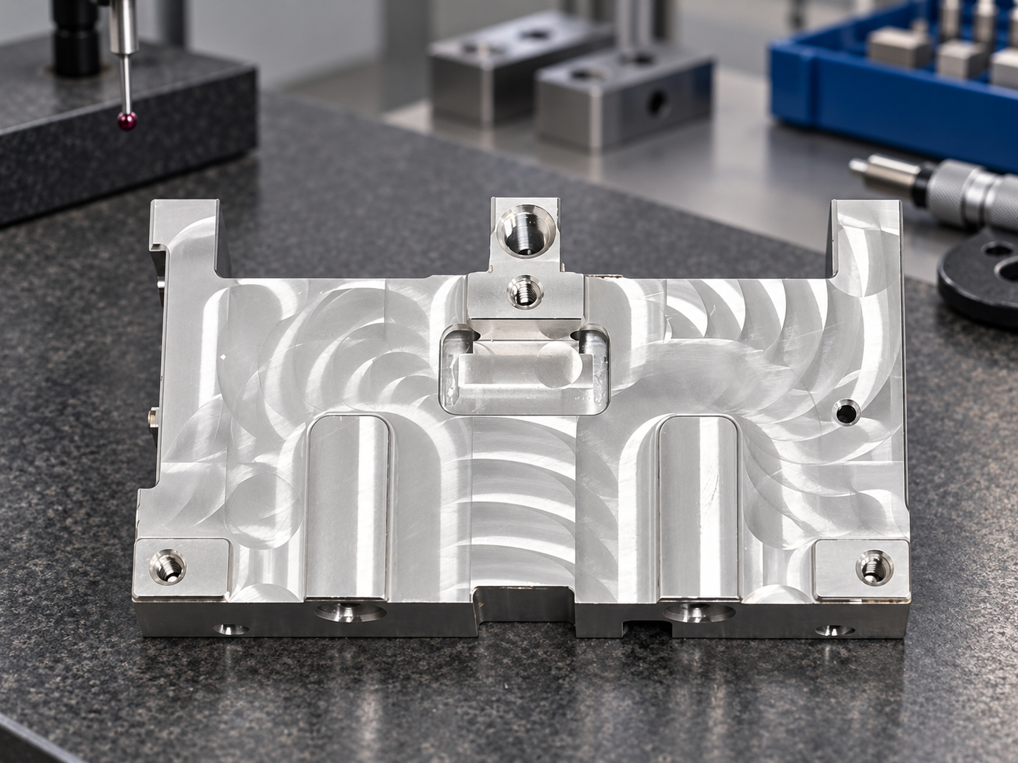
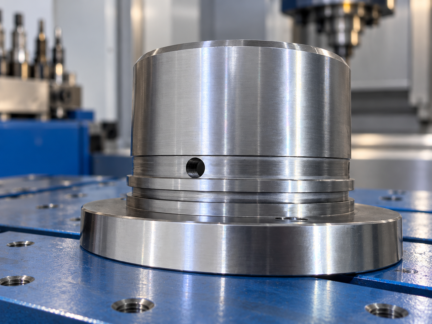
Even a carbide end mill or coated tool needs an application match. Harder materials, interrupted edges and heat-treated stock can shift the grade, coating, engagement and setup review.
Extra cutting edges reduce flute space, so a full-width slot or difficult chip shape can change the trade-off. An end mill that broke immediately is a reason to review material, overhang, engagement and chip evacuation before choosing a replacement.
We process carbon and alloy steels, stainless steels, nickel-based alloys and aluminum alloys in our custom machining work. NIST’s feature-based process-planning model supports reviewing part design, manufacturing features, operations and tool requirements together. [2]
- carbon steel
- alloy steel
- stainless steel
- nickel-based alloy
- aluminum alloy
- chip evacuation
End Mill Geometry and the Surface It Leaves
A square end mill can form a flat floor and sharp internal step, while a ball end mill supports blended 3D contours. A corner-radius end mill bridges those geometries by keeping a flat center with a radiused cutting corner.
Geometry Specifications
Square end
Useful for floors, side walls, pockets and profiles where the toolpath and corner requirements suit a flat end.
Geometry Specifications
Ball nose
Ball cutters generate changing contact as the tool follows curved surfaces. Step-over, tool orientation and remaining stock belong in the finish plan.
Geometry Specifications
Corner radius
Radiused cutters can protect the cutting corner and leave a specified fillet. The drawing radius and mating geometry must agree with the toolpath.
Process Variables
Flute count needs context.
The number of flutes changes the balance between chip space and cutter core, while engagement and material decide how much of that trade-off matters.
System Diagnostics
New tool, old problem.
A new end mill can still chatter when overhang, holder condition, workholding, engagement or machine dynamics are wrong. Replacing the cutter without checking the system can leave the root cause untouched.
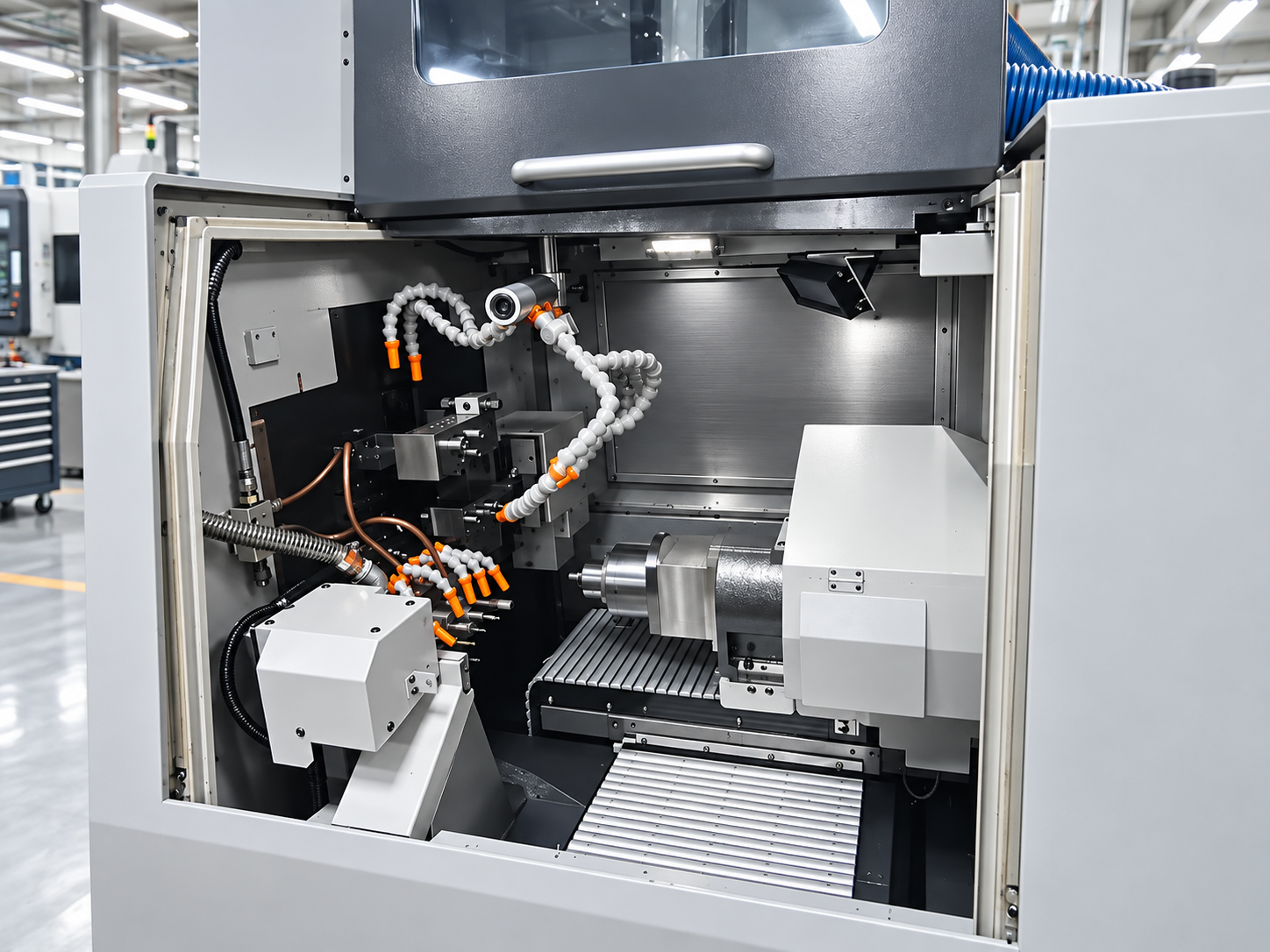
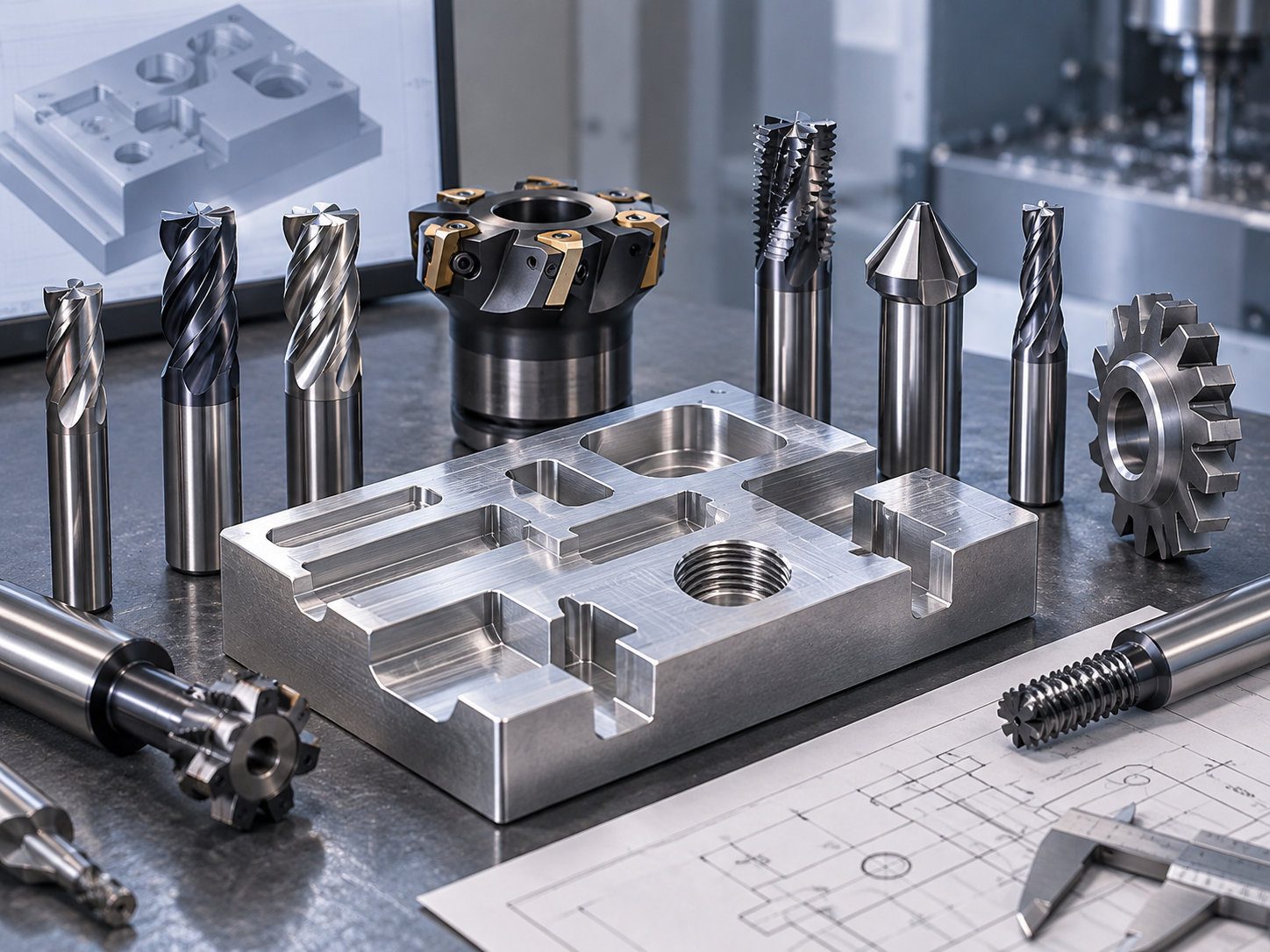
Types of Milling Cutters by Machined Feature
This table provides a shortlist of candidate tool families based on initial feature criteria; it is not a finalized tooling or workholding plan. Each numbered row connects a cutter family and common feature with the drawing evidence and process checks needed before committing to that toolpath.
| No. | Cutter family | Feature direction | Drawing evidence | Process checks |
|---|---|---|---|---|
| 01 | Face mill | Broad, accessible planar face | Face boundaries, stock and edge condition | Coverage, spindle load, clamp clearance |
| 02 | Square end mill | Pocket floor, wall, step or profile | Depth, inside radii and floor callout | Reach, ramp entry, chip exit, deflection |
| 03 | Ball end mill | 3D contour and blended surface | Surface model, allowance and finish zone | Contact point, step-over, holder clearance |
| 04 | Corner-radius end mill | Floor plus radiused internal corner | Fillet radius and mating requirement | Corner engagement, remaining stock |
| 05 | Roughing end mill | Remove a large amount of material before a separate finish stage | Stock model and finish allowance | Machine load, chip control, second-stage access |
| 06 | Side-and-face cutter | Side feature or slot with arbor access | Slot width, side faces and access envelope | Arbor support, workholding, collision path |
| 07 | T-slot or keyseat cutter | Undercut, T-slot or keyseat form | Neck, head, entry and relief dimensions | Entry route, neck clearance, chip removal |
| 08 | Thread milling cutter | Screw thread by interpolated path | Thread form, pitch, class and depth | Machine motion, relief, gauge plan |
| 09 | Chamfer or angle cutter | Edge break, bevel, V-slot or angle | Angle, width and edge direction | Tip clearance, burr direction, inspection |
| 10 | Form, gear or hollow mill | Dedicated profile, tooth or outside form | Profile definition and datum scheme | Special geometry, indexing, verification method |
From Drawing to Quotation and Lead Time
The selected milling cutter family is only one factor in the scope and cost of a custom machining order. Raw material specifications, geometric complexity, production quantity, setup frequency, inspection requirements, finishes and delivery timeline also affect the quotation.
01
Quotation
We return an engineer-reviewed quotation after reviewing the drawing and production requirements.
02
Prototype schedule
Prototype parts ship after drawing approval and process review; timing is confirmed in the quotation.
03
Production schedule
Production runs are scheduled after process review, with timing confirmed in your quotation.
04
Starting quantity
Prototype orders start only after quantity, drawing and process-route review.
05
Design files
STEP, IGES and PDF files may accompany the drawing for initial review.
06
Confidential review
We review drawings only after confidentiality and NDA requirements are identified for the detailed review.
Face Mill vs End Mill in a Manufacturing Plan
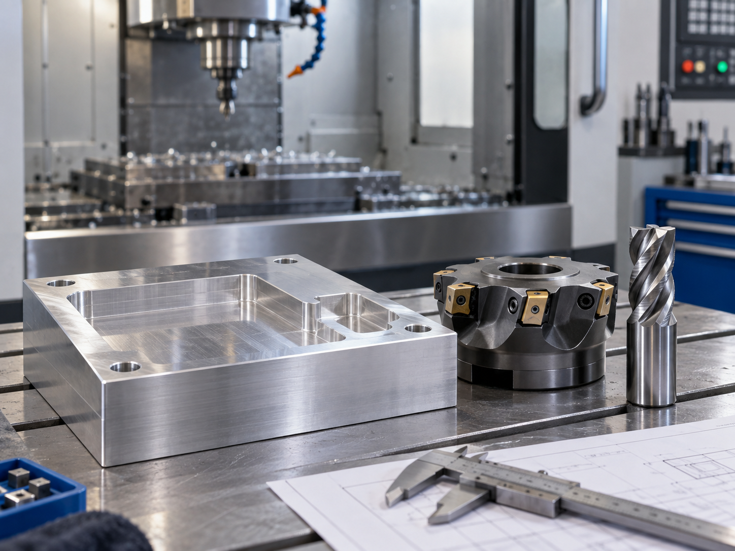
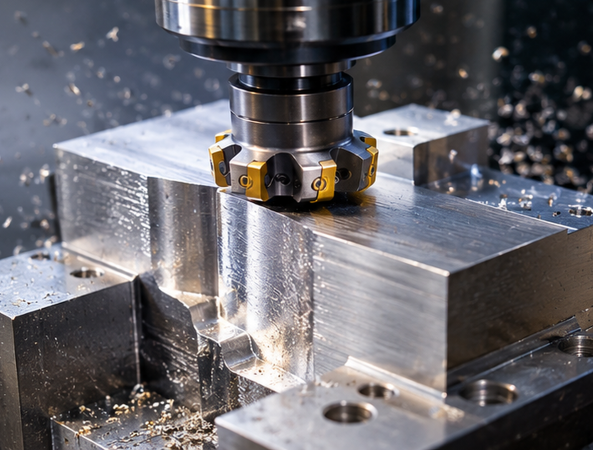
A face mill and an end mill can both contribute to a planar surface, so “face equals face mill” is too rigid. When a cutter axis is perpendicular to a flat surface, either the face-milling family or a flat-end toolpath can enter the review; engagement and access decide the route.[3]
The trade-off exists because power, stability, insert engagement, clamp clearance and the rest of the toolpath create different risks in each application. Send your drawing for a specific engineering review when those conditions are not verified.
- The target is a broad open face.
- The cutter body and holder clear clamps and edges.
- The machine can support the planned engagement.
- Required shoulders and interrupted regions are accounted for.
- The tool must enter pockets or local regions.
- Side walls, contours or internal radii matter.
- A smaller diameter is needed for access.
- One setup combines facing with other local features.
Follow the machine and tool manufacturers’ instructions, keep required guards functional, secure the workpiece and inspect tooling condition before operation. Stop the spindle before reaching into the cutting area or clearing chips, and use an appropriate tool rather than bare hands.[5][6]
guard condition
secure workholding
tool condition
program clearance
stopped-spindle
machine instructions
Operating boundary.
Guarding requirements depend on machine mode and the documented hazard, so this guide does not replace a site risk assessment or local rules.[7] Do not treat this page as a setup instruction, speed-and-feed chart or legal-compliance determination.
Cutter Choice Is a System Decision
NIST’s feature-based process-planning work connects a part design to selected milling operations and tool requirements. That principle supports a review sequence in which each milling operation, setup and cutting tool is planned together rather than naming a cutter in isolation.[2]
Identify faces, pockets, slots, threads, radius features, datums and critically important geometric interfaces in your CAD/CAM model.
1
2
Define the feature orientation from its datum or reference geometry. Check the surrounding space for workholding, the toolholder envelope, standard or special tool reach and collision risks.
Organize machining in appropriate stages: roughing for material removal, semi-finishing for geometric control and profile refinement, and finishing for the required surface attributes and tolerance. Specific form-geometry tasks may require a dedicated toolpath sequence or specialized tooling.
3
4
Correlate requirements at the feature level and develop criteria to verify compliance by measurement against the print and documentation in inspection reports.
We review the drawing and material before fixing a machining route. We program around feature access, workholding and the available machine envelope, then align inspection planning with the drawing’s critical requirements.
“We need the feature, material, access and inspection requirement before a cutter name becomes a process decision.”
Zhenling engineering review principle
Program-to-floor handoff.
The machinist also needs a verified setup, tool offsets, clearance plan and inspection route. A face mill or end mill label cannot supply those controls by itself.
Inputs that change the shortlist
Part size, feature depth, inside radius, wall thickness, stock form, heat-treatment state, datum scheme and mating surfaces.
Inputs that change verification
Critical dimensions, geometric controls, surface callouts, thread gauges, reporting needs and assembly interfaces.
Parts We Manufacture, Not a Cutter Catalog
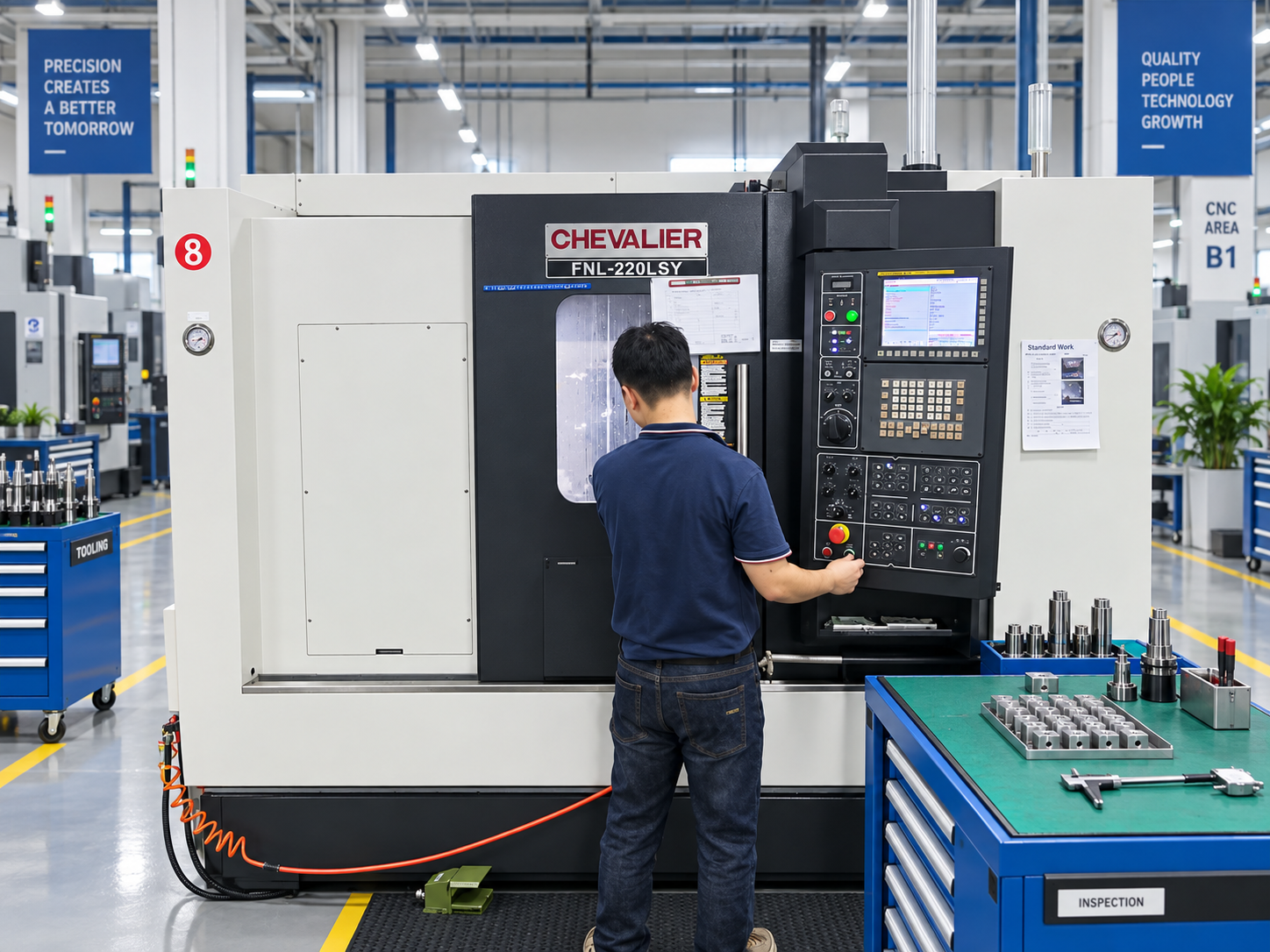
Shanghai Zhenling Hardware Co., Ltd. was established in 2006 with manufacturing in Jiashan County, Zhejiang Province, China. Our 8,000 square meter site includes a 6,000 square meter workshop.
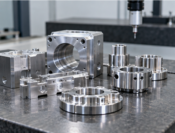
Machining equipment
We operate CNC wire-cut EDM, lathes, milling machines, grinding machines, boring machines and radial drilling machines.
Machining centers
Our equipment includes 3-axis and 4-axis machining centers and imported 5-axis machining centers.
Made-to-print scope
We manufacture complete machine assemblies, flanges, rollers, bent pipes, valve bodies, plugs and custom-machined parts.
Where a Cutter Table Stops Being Reliable
This table cannot determine clamp proximity, tool projection from the holder, machine runout, machine dynamics or the selected tool trajectory. It cannot resolve ambiguous or incomplete print notes or dictate which critical specification takes precedence when requirements conflict.
- Deep cavities or long reach
- Thin walls or flexible features
- Interrupted surfaces
- Small internal radii
- Hard or abrasive material conditions
- Critical surface or inspection zones
- Spindle speed or feed
- Achievable tolerance
- Surface-finish result
- Tool life
- Cycle time
- Legal or safety compliance
Engineering Policy
We do not sign off that a specific part is manufacturable using only generic references and cutter lists. Our drawing and detail-focused review process considers feature context, workholding, machine resources and inspection requirements before production.
FAQ: Frequently Asked Questions About Types of Milling Cutters
There is no single useful count because cutters can be grouped by function, end geometry, mounting, construction, tool material or application. A flat list often counts overlapping labels as separate families.
A face mill is centered on broad surface work, while an end mill can address floors, side walls, pockets and contours. Either can contribute to a planar surface when the toolpath and access support it, so the part and setup decide the shortlist.
No. More cutting edges can increase cutter-core area, while fewer flutes leave more chip space; material behavior, engagement, reach and the finish plan change the balance.
Roughing end mills are designed for material-removal stages that leave stock for later operations. Their use does not remove the need to plan finishing allowance, chip control and machine load.
A fly cutter is an arbor-mounted rotary cutter associated with broad flat-surface work. Cutter balance, sweep, machine condition and guarding need machine-specific review before use.
It can in some process plans, but that is not a default rule. Stock allowance, wear state, edge geometry, reach and surface requirements can favor separate tools or operations.
Send part geometry, a dimensioned drawing, material, quantity, critical features, surface and edge requirements, inspection needs, application context and the requested schedule. STEP, IGES and PDF files may accompany a dimensioned drawing for initial review.
This page is an educational guide for buyers of custom-machined parts. Zhenling's offer here is drawing-based CNC machining review, not a public milling cutter catalog.