

CNC Machining Knowledge Library: Reference Sections, Data and Tools
Zhenling runs this CNC machining knowledge library alongside a CNC machining service, for engineers and buyers who work from drawings. We machine non-standard metal components from customer drawings or samples at our own factory in Jiashan County, Zhejiang.
CNC machining involves using a computer numerical control program to move a cutting tool along defined tool paths to remove material from a workpiece until the part matches its drawing. The same G-code runs part after part, so repeatability comes from the drawing, the setup and the program. For more information on CNC machining, read our CNC fundamentals guide.
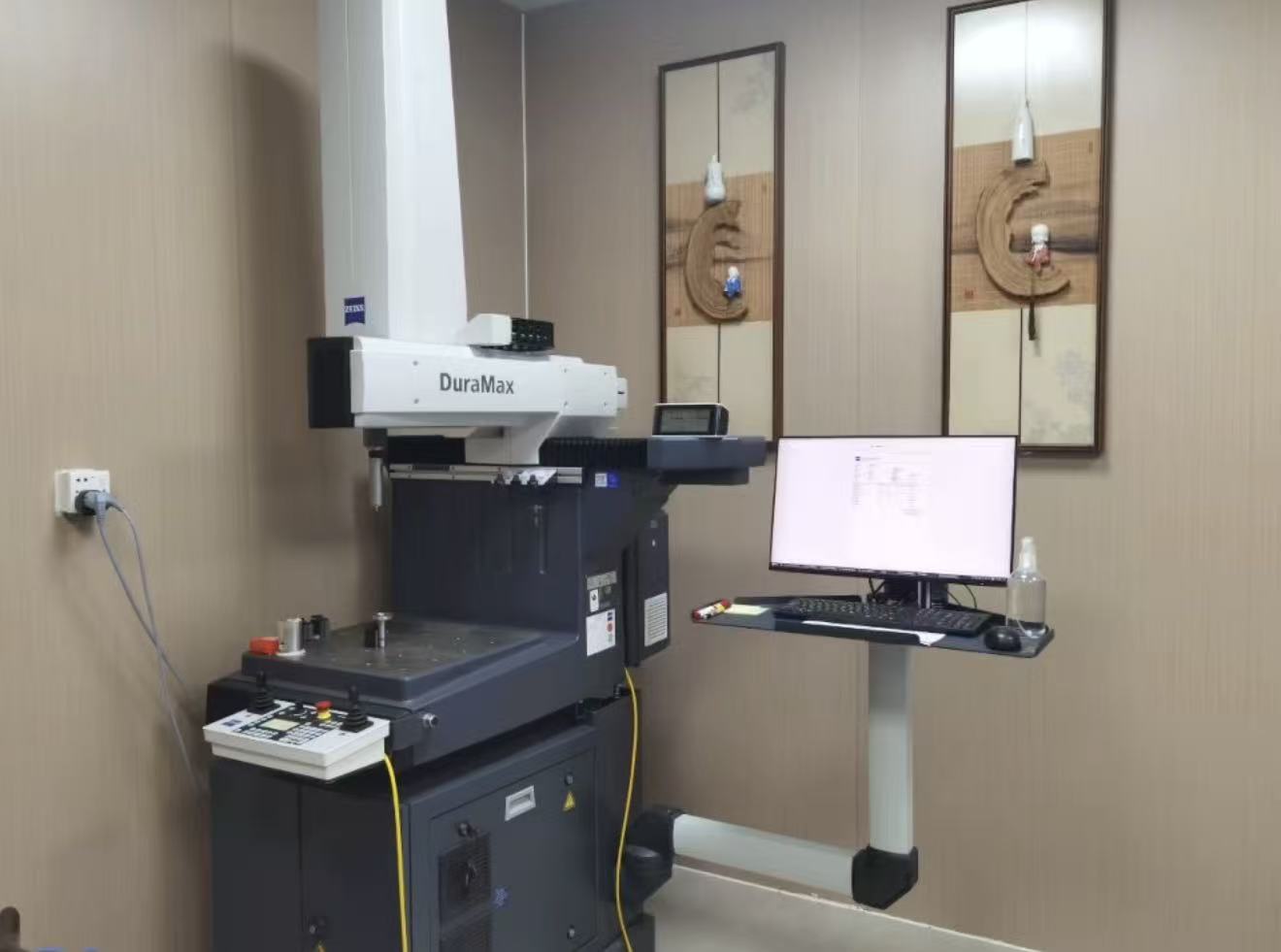
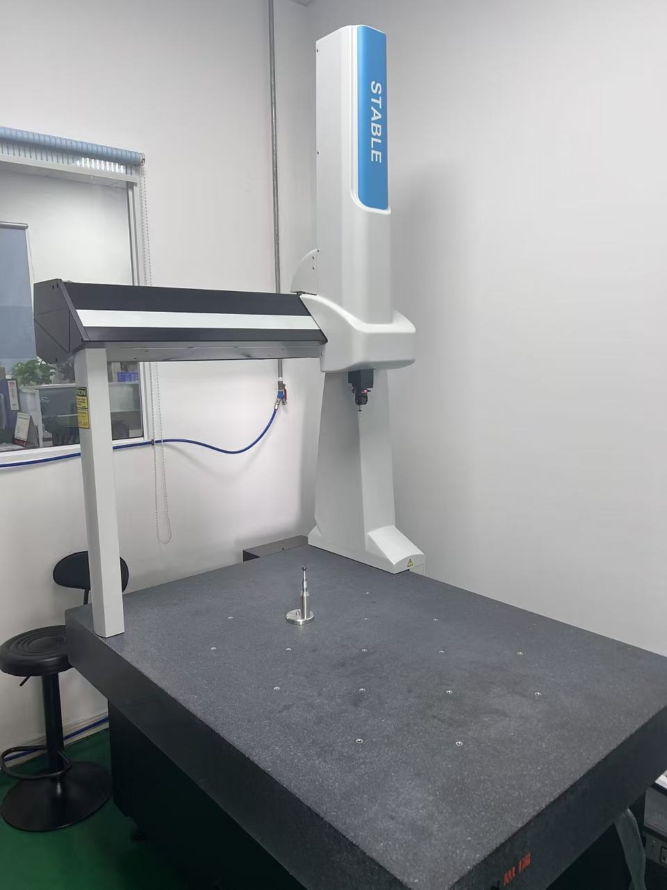
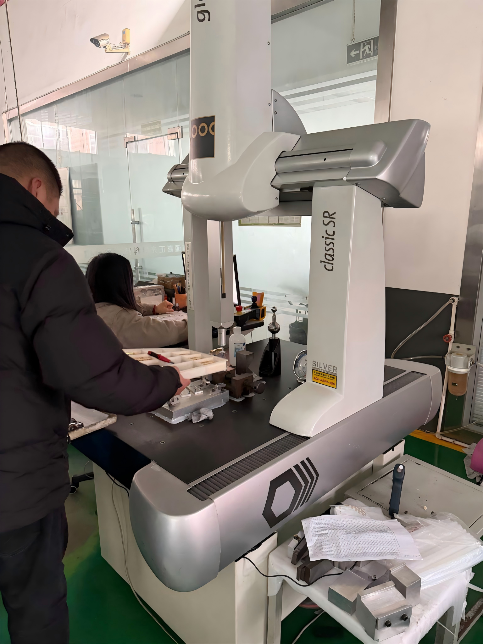
How a finished part is measured against its drawing: GD&T symbols under ASME Y14.5 and ISO 1101, datums, inspection methods and what a measurement report shows.
CNC Metrology →Milling cutter types, flute counts and workholding options, and the considerations when choosing a tool route for each feature on the part.
CNC Tooling Guides →Removing material through milling, turning, drilling and boring, and choosing the process family that suits a given part geometry.
Machining Processes →G-code blocks in the ISO 6983-1 program format, the machine coordinate system and work offsets, and the checks a CNC program needs before release.
CNC Programming →Machinability ratings, scales of hardness and the effect of material grade on cutting speeds and tool wear.
Material Properties →Speeds and feeds, tap drill sizes, and a list of the inputs needed when generating a machining cost quote, each with a worked example.
Machining Calculators →The Drawing-to-Part Reading Order for CNC Machining Work
A manufacturing drawing turns into a machined part through six decisions, and each one depends on the one before it. The library follows the same order, so you can check CNC machining work step by step instead of jumping between topics.
STEP 01
Material
Grade and hardness set the cutting speed, the tool and the surface you can reach.
STEP 02
Process
Milling, turning or both, and which features need a second setup.
STEP 03
Tooling and workholding
Cutter geometry and the way the workpiece is held decide which features a tool can reach, and every fixture is a compromise between access and rigidity.
STEP 04
Programming
CAD geometry becomes CAM tool paths and G-code, set against the ISO 841 machine axes and a work offset.
STEP 05
Calculation check
Spindle speed, feed rate and tap drill sizes are worked out before the first cut.
STEP 06
Metrology
The finished part is measured against the drawing, feature by feature.
Key CNC Machining Terms and Where to Read Them
The following terms show up frequently as work passes between a drawing, a CNC program and an inspection report. Each row defines a term and gives the section that covers it in detail.
TERM
WORKING MEANING
G-code
The block-by-block instruction language a CNC machine reads; the program format is set out in ISO 6983-1.
CAM
Computer-aided manufacturing software that turns CAD geometry into tool paths and G-code.
Work offset
The stored distance from machine zero to the part zero the program uses, called up with codes such as G54.
Machine axes
Linear axes X, Y and Z and rotary axes A, B and C, named under ISO 841; a multi-axis machine controls more than three of them.
End mill
A rotating cutter with teeth on its end and sides, used for slots, pockets and profiles.
Workholding
The vise, chuck or fixture that holds the workpiece rigidly while it is cut.
Spindle speed
Rotational speed of the tool or workpiece in rpm, worked out from cutting speed and diameter.
Feed per tooth
The chip load each cutting edge takes per revolution, in mm/tooth; feed rate = feed per tooth × number of teeth × rpm.
General tolerance
The tolerance that applies to every dimension without its own tolerance, set by a title-block note such as ISO 2768-m under ISO 2768-1.
GD&T
Geometric dimensioning and tolerancing: symbols that control form, orientation, location and run-out, defined in ASME Y14.5 and ISO 1101.
First-article inspection
Measuring the first part from a new setup against every drawing dimension before the batch continues.
Machinability
How easily a material cuts, expressed as a rating against a free-cutting reference steel.
What We Commit To on Every Order
Sourcing machined parts gets harder when there is inconsistency between suppliers on the same drawing. These are the terms behind every quotation we issue, and the same wording is written into your quote.
Quote response
Quotes are returned within 2–3 working days of receiving your drawing, reviewed by an engineer.
Prototype lead time
Prototype parts ship in 7–15 business days after drawing approval; surface finishing, heat treatment and transit are quoted separately.
Small-batch lead time
Small-batch orders ship in 7–15 business days after drawing approval.
Production runs
Production runs follow a schedule confirmed in the written quotation after sample approval.
Order quantity
Prototype orders start from 1 piece; production quantities are confirmed in the quotation.
First-article parts
First-article parts are available, and the inspection scope is stated in the quotation.
General tolerance
Metal parts are held to ISO 2768-m unless your drawing specifies otherwise.
Drawing files
We work from STEP (STP), IGES (IGS), DWG, DXF and PDF files.
Confidentiality
Your drawings are handled as confidential; an NDA is available on request before drawing review.
Shipping terms
We ship EXW and FOB; other Incoterms on request.
Inspection documents
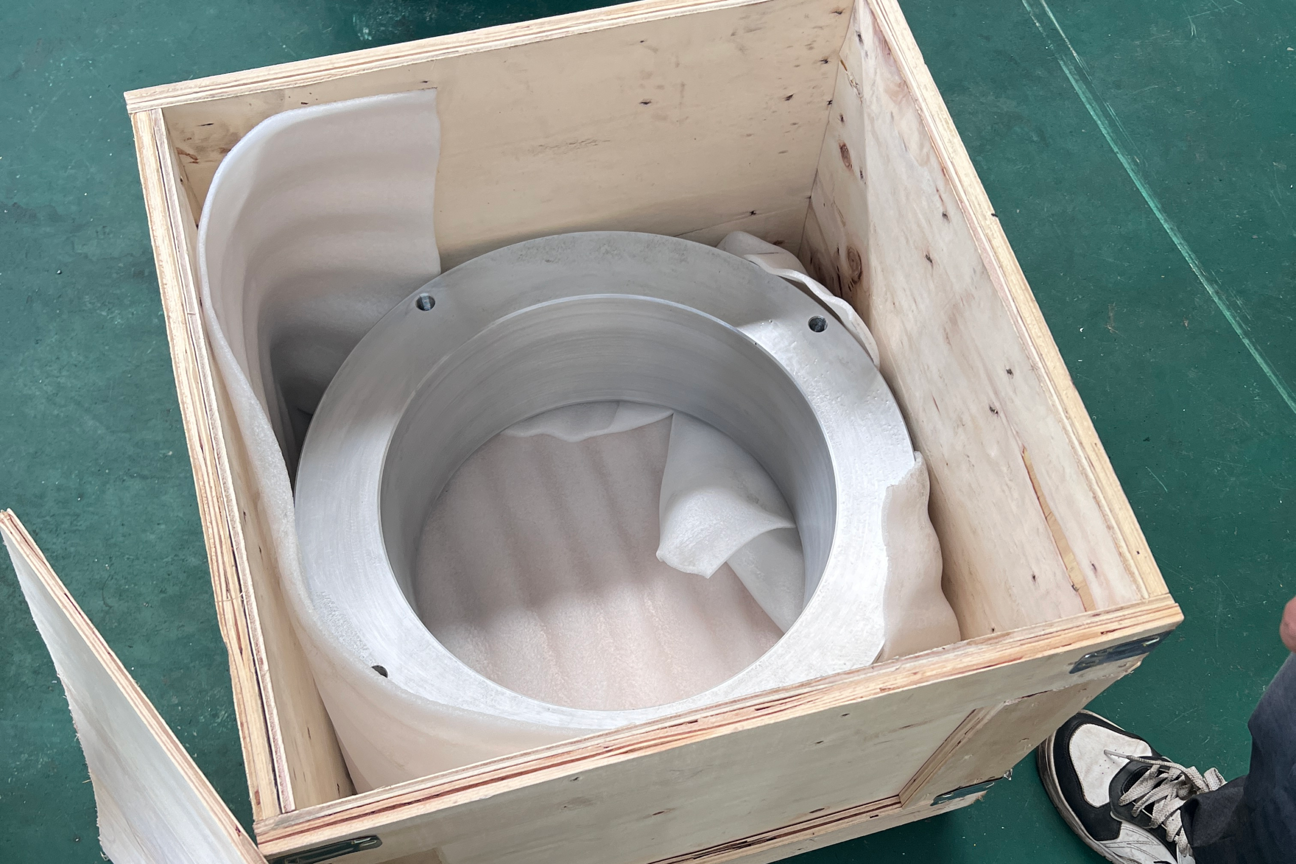
Dimensional inspection reports and material certificates are available on request and scoped in the quotation.
Where parts are machined
At our own factory in Jiashan County, Zhejiang: an 8,000 m² (86,111 ft²) site with a 6,000 m² (64,583 ft²) workshop.
ISO 2768 General Tolerances at a Glance
ISO 2768-1:1989 sets general tolerances for linear and angular dimensions that carry no tolerance of their own, on parts produced by metal removal or formed from sheet metal. The medium class (m) below covers sizes from 0.5 mm to 4,000 mm and works as a machining reference chart, with inch values converted from the millimetre limits.
Note: Sizes below 0.5 mm get their tolerance written next to the dimension.
ISO last reviewed and confirmed ISO 2768-1:1989 in 2022 and lists a revised ISO 2768 under development, so confirm against the edition your drawing names.
ISO last reviewed and confirmed ISO 2768-1:1989 in 2022 and lists a revised ISO 2768 under development, so confirm against the edition your drawing names.
| Nominal size (mm) | Nominal size (in) | Class m (mm) | Class m (in) |
|---|---|---|---|
| 0.5 to 3 | 0.02 to 0.12 | ±0.1 | ±0.004 |
| over 3 to 6 | 0.12 to 0.24 | ±0.1 | ±0.004 |
| over 6 to 30 | 0.24 to 1.18 | ±0.2 | ±0.008 |
| over 30 to 120 | 1.18 to 4.72 | ±0.3 | ±0.012 |
| over 120 to 400 | 4.72 to 15.75 | ±0.5 | ±0.020 |
| over 400 to 1000 | 15.75 to 39.37 | ±0.8 | ±0.031 |
| over 1000 to 2000 | 39.37 to 78.74 | ±1.2 | ±0.047 |
| over 2000 to 4000 | 78.74 to 157.48 | ±2 | ±0.079 |
| Nominal size | f (fine) | m (medium) | c (coarse) | v (very) |
|---|---|---|---|---|
| 10 mm (over 6 to 30) | ±0.1 mm | ±0.2 mm | ±0.5 mm | ±1 mm |
| 50 mm (over 30 to 120) | ±0.15 mm | ±0.3 mm | ±0.8 mm | ±1.5 mm |
| 200 mm (over 120 to 400) | ±0.2 mm | ±0.5 mm | ±1.2 mm | ±2.5 mm |
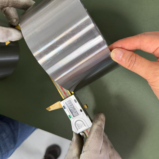
Reading CNC machining tolerances
- Drawing note: “General tolerances ISO 2768-m”.
- Dimension: 50 mm, with no tolerance written beside it.
- Band: over 30 to 120 mm, so the permissible deviation is ±0.3 mm (±0.012 in).
- Accepted size: 49.7 mm to 50.3 mm (1.957 in to 1.980 in).
A tighter tolerance is not always a better part. Past what the function needs, the trade-off is extra finishing passes and inspection time, and tightening every dimension is a mistake because it raises the risk of rework without improving the fit.
Dimensions that need a tighter limit get their own tolerance on the drawing, and we review each of those at drawing review.
Acceptance criteria come from the drawing and its measurement rules. The dimensional inspection guide provides additional information.
ISO 2768 tools
- Look up an ISO 2768 tolerance for any size and class, with upper and lower limits in mm and inches.
- Decode a title-block tolerance note such as ISO 2768-mK or ISO 2768-f.
- Identify the class of your tolerance prior to documenting the drawing.
- Convert a ± tolerance into limits in either unit of measurement.
Milling and Turning Capabilities and Equipment
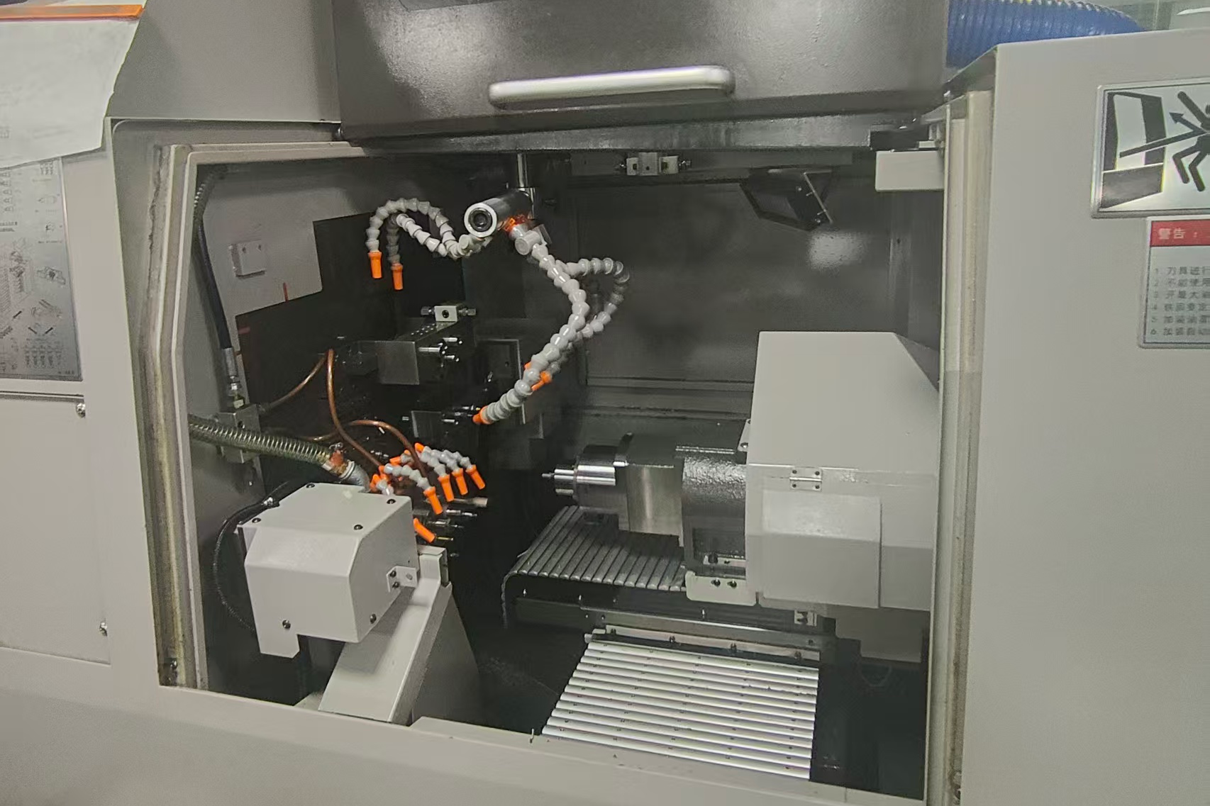
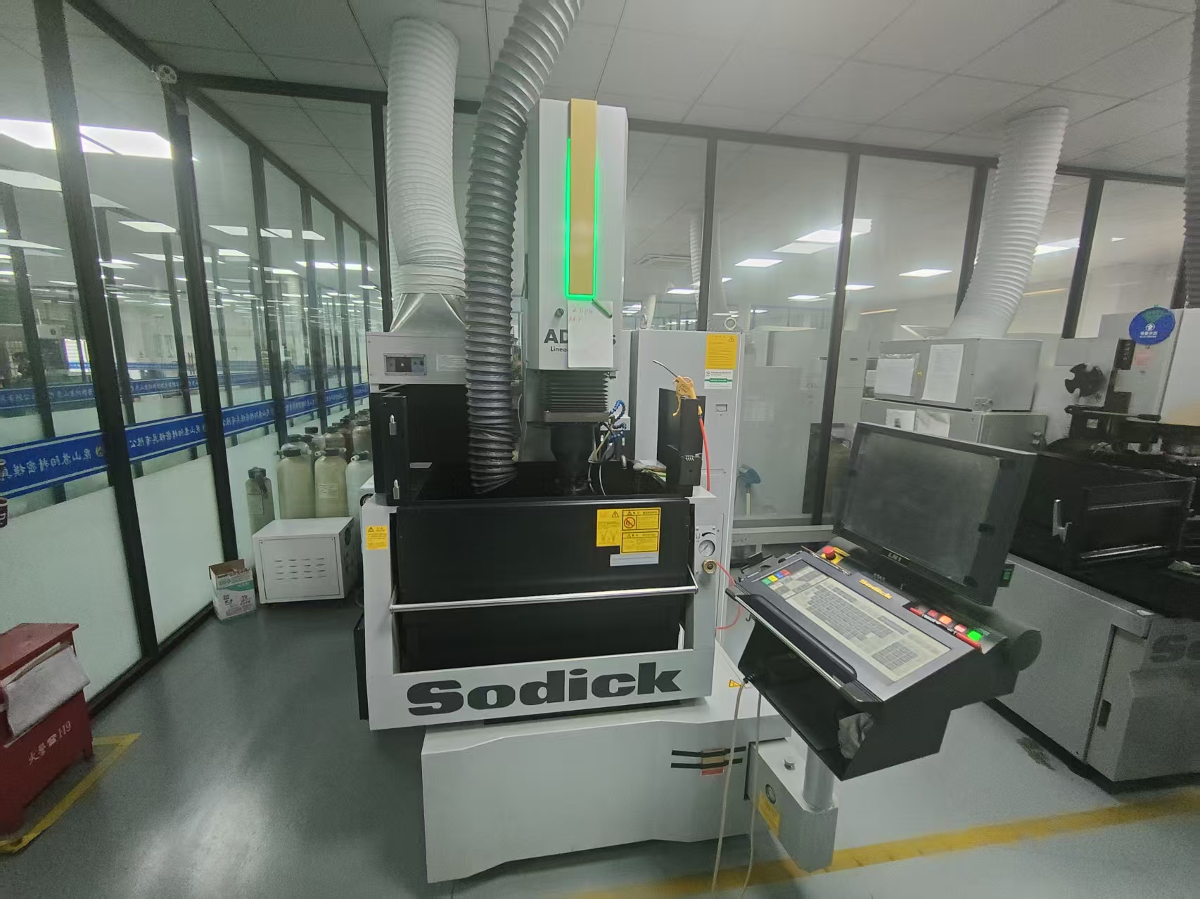
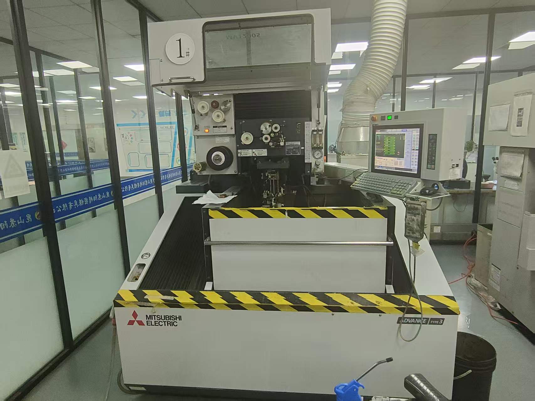
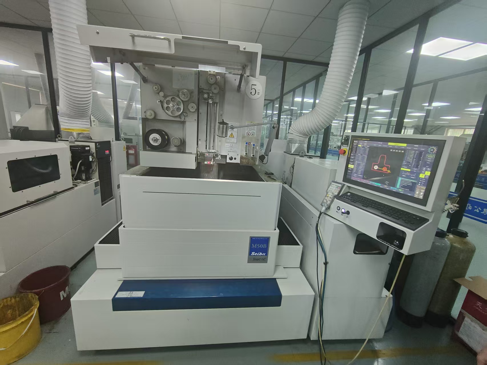
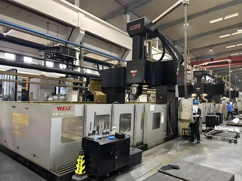
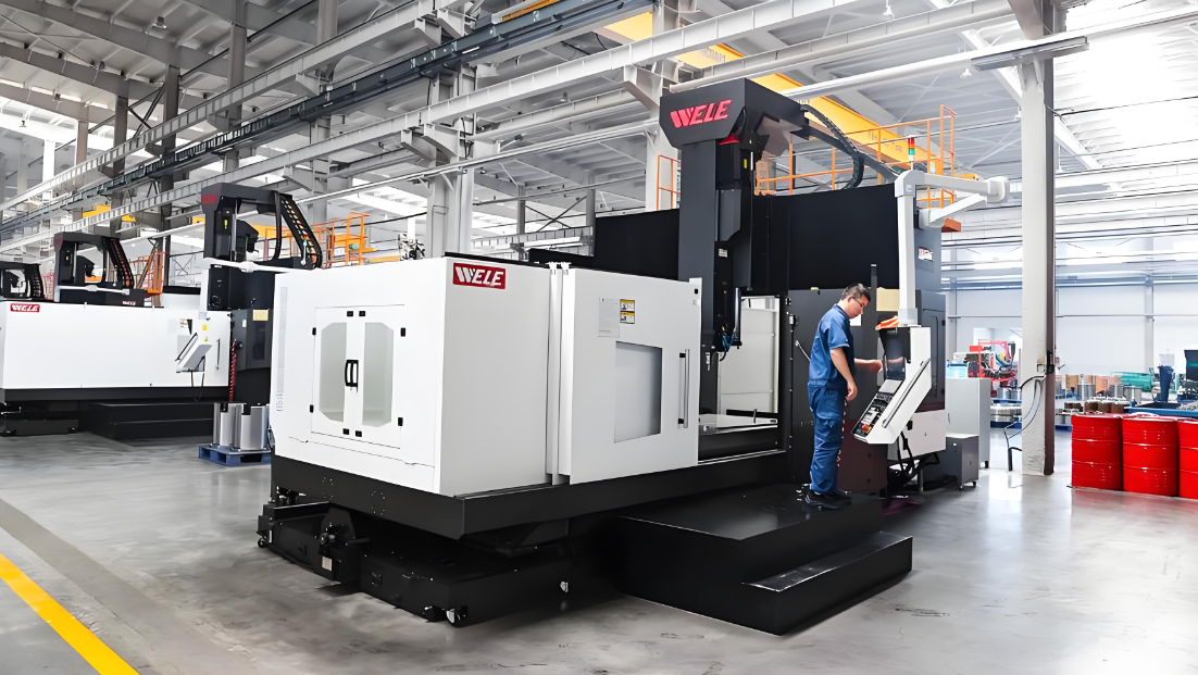
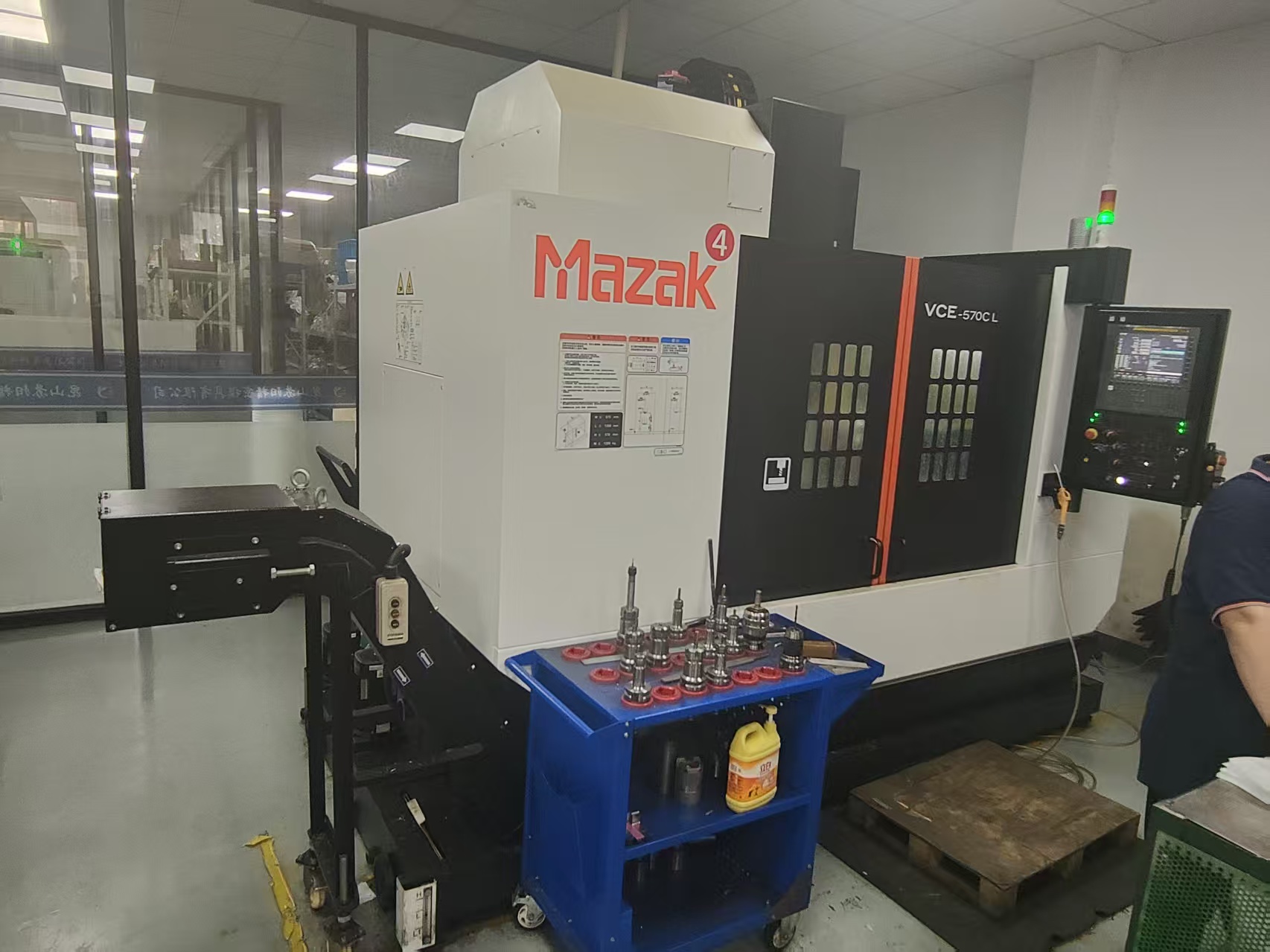
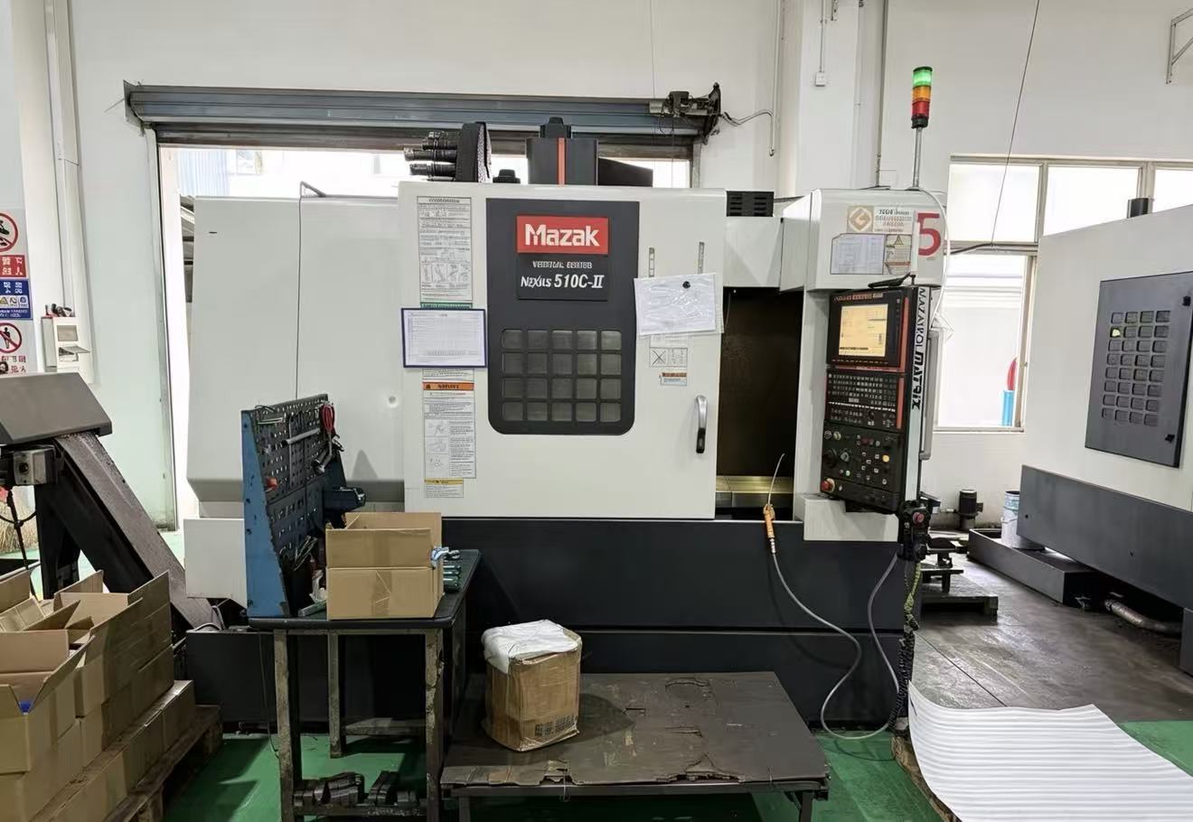
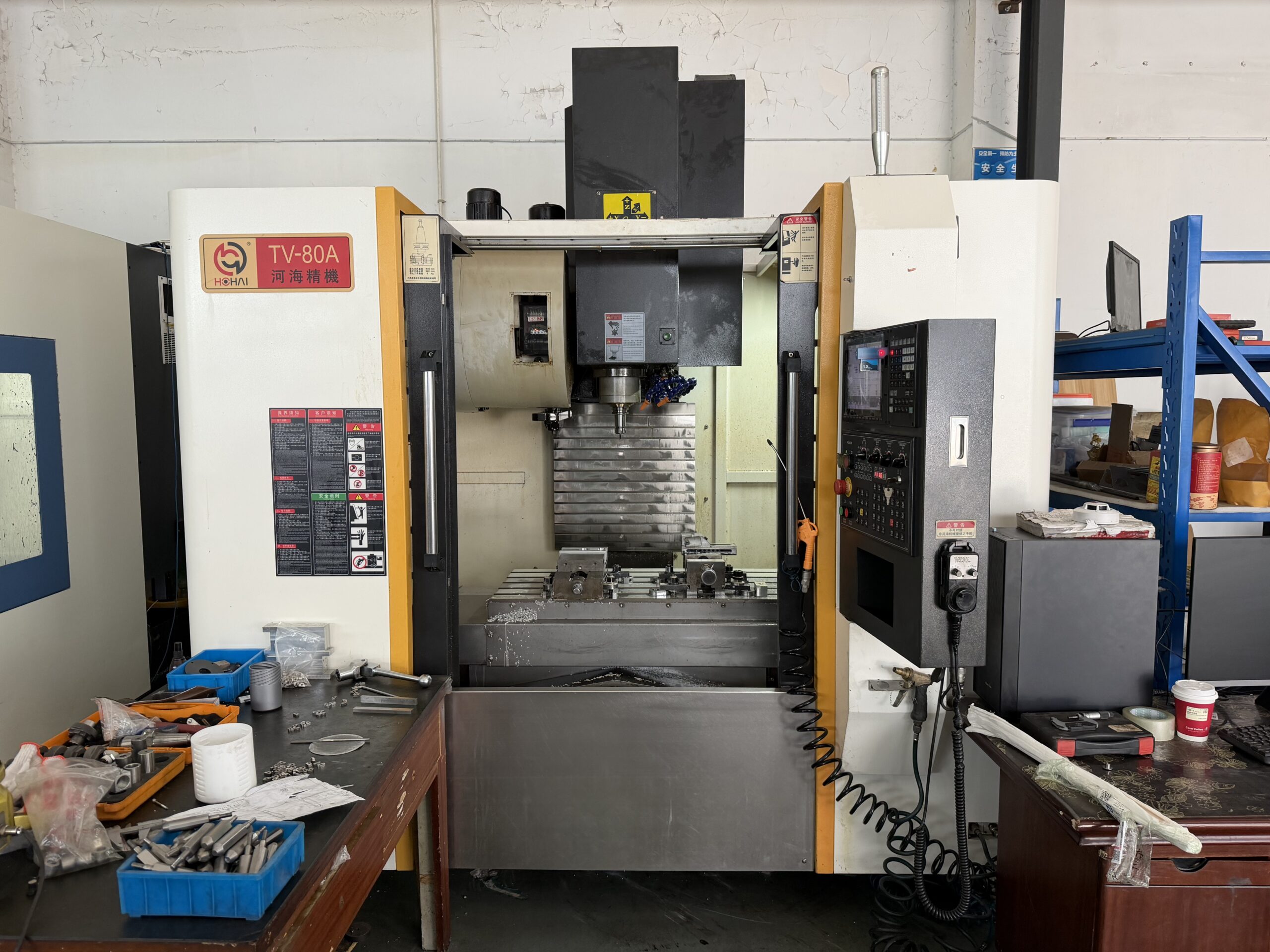
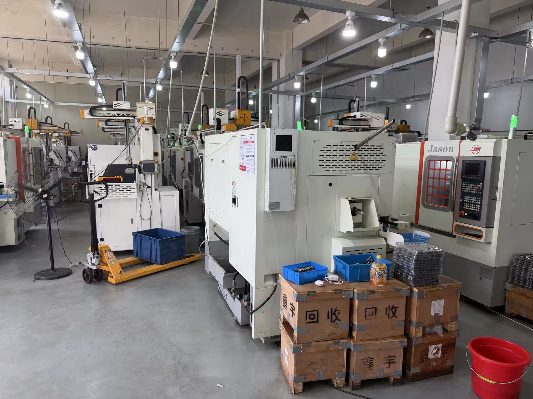
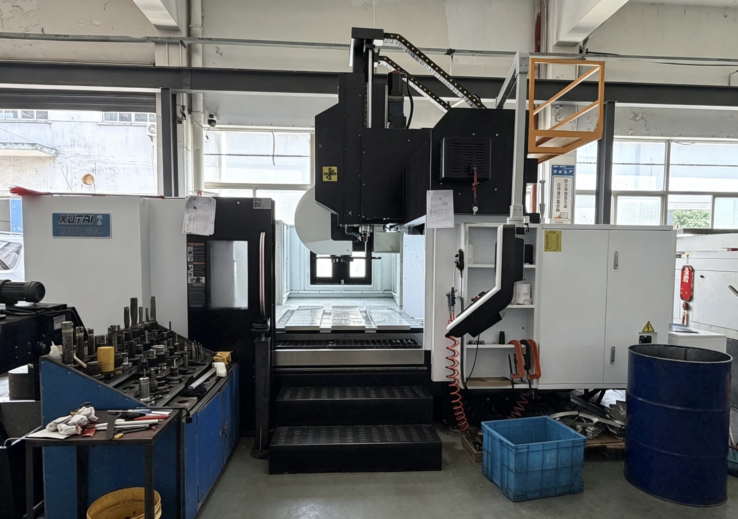
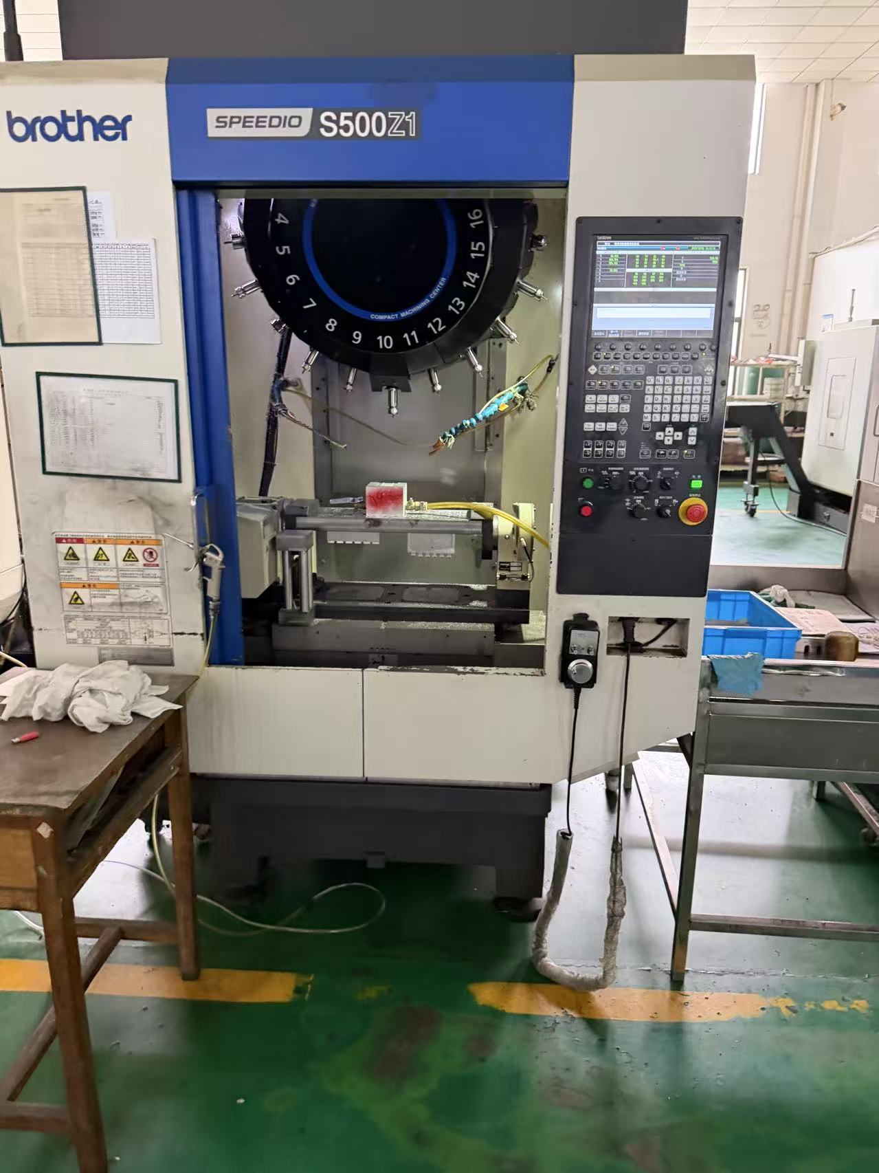
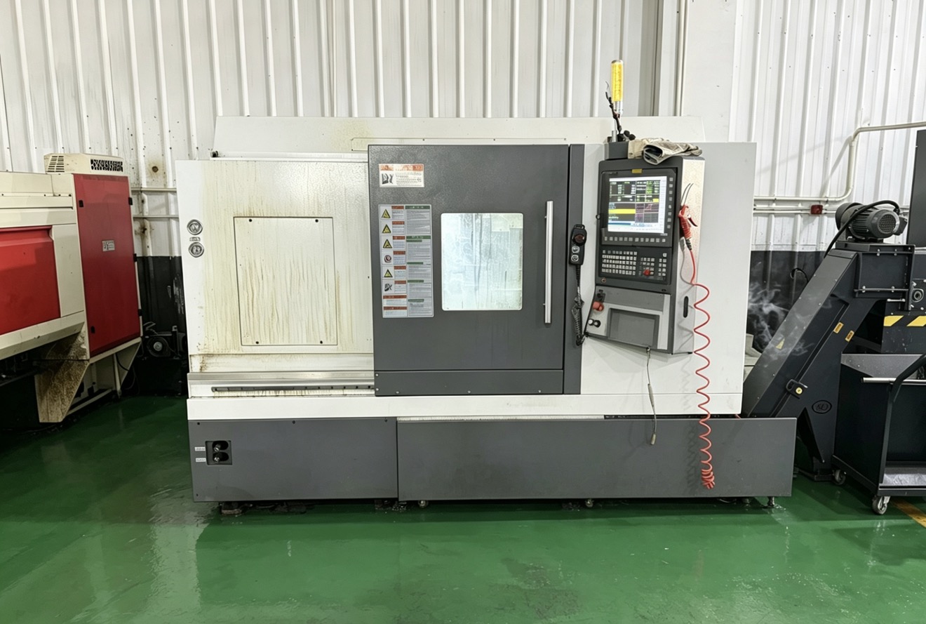
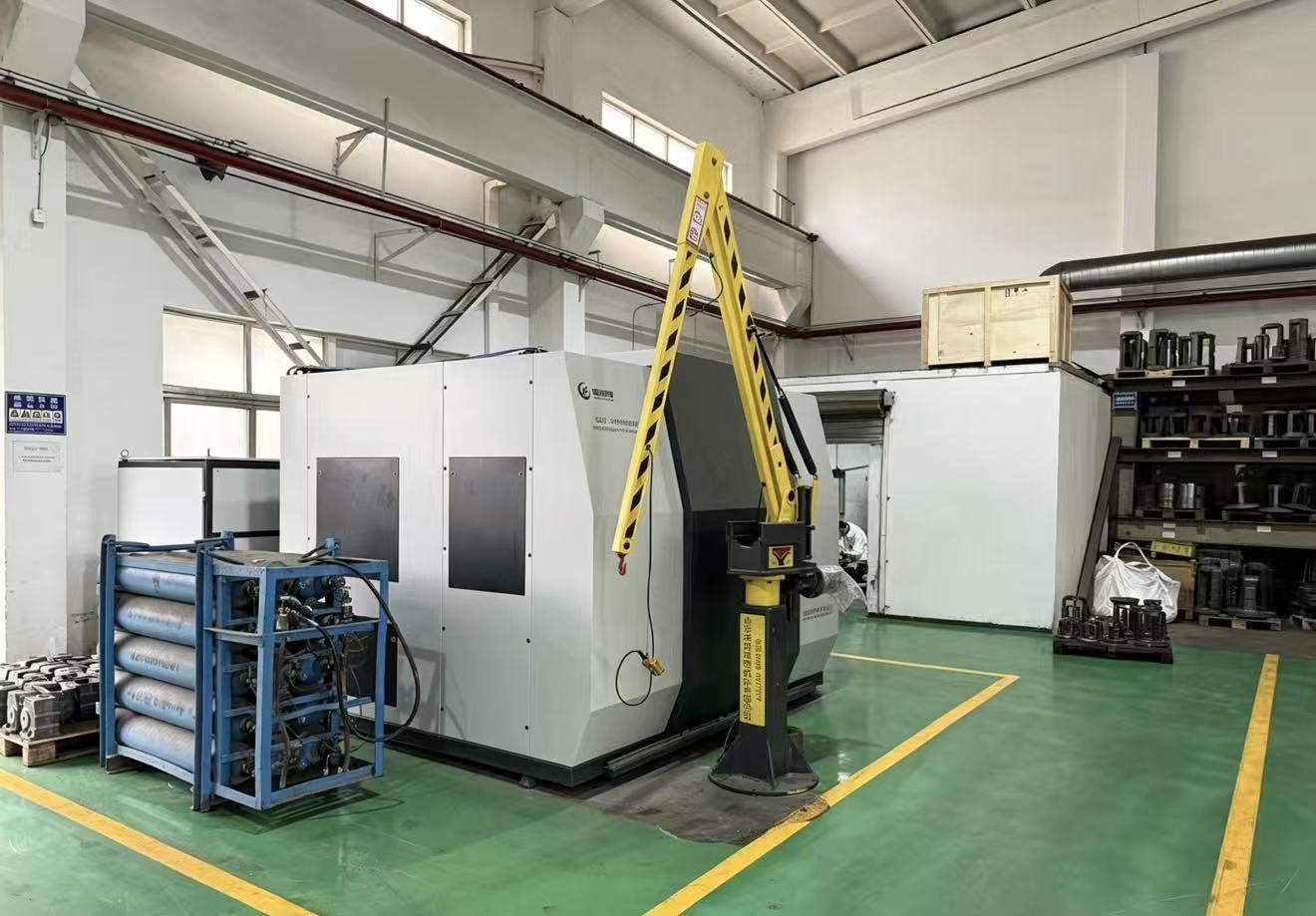
Zhenling was established in 2006, and we machine non-standard metal components from customer drawings or samples. The work runs at our factory in Jiashan: an 8,000 m² (86,111 ft²) site with a 6,000 m² (64,583 ft²) workshop. The types of CNC machine we run are grouped below by the work they do.
CNC milling and machining centers
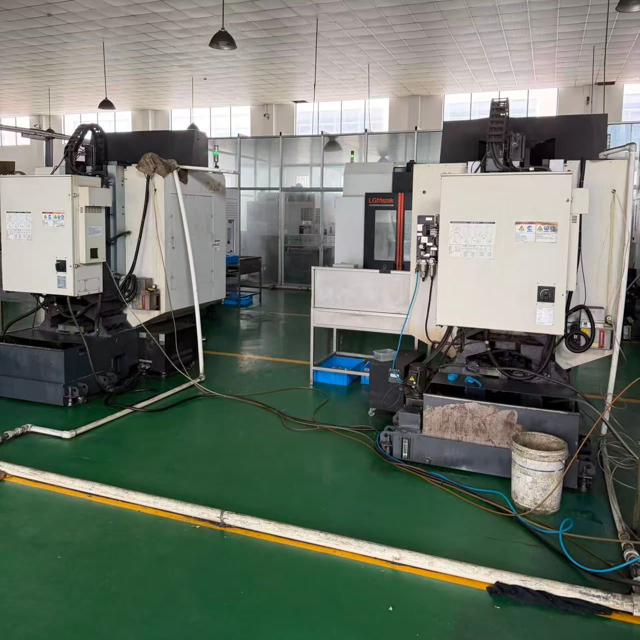
3-axis and 4-axis machining centers and imported 5-axis machining centers handle prismatic parts, pockets, bolt-hole patterns and complex parts with multi-axis features on several faces.
Turning, grinding and boring
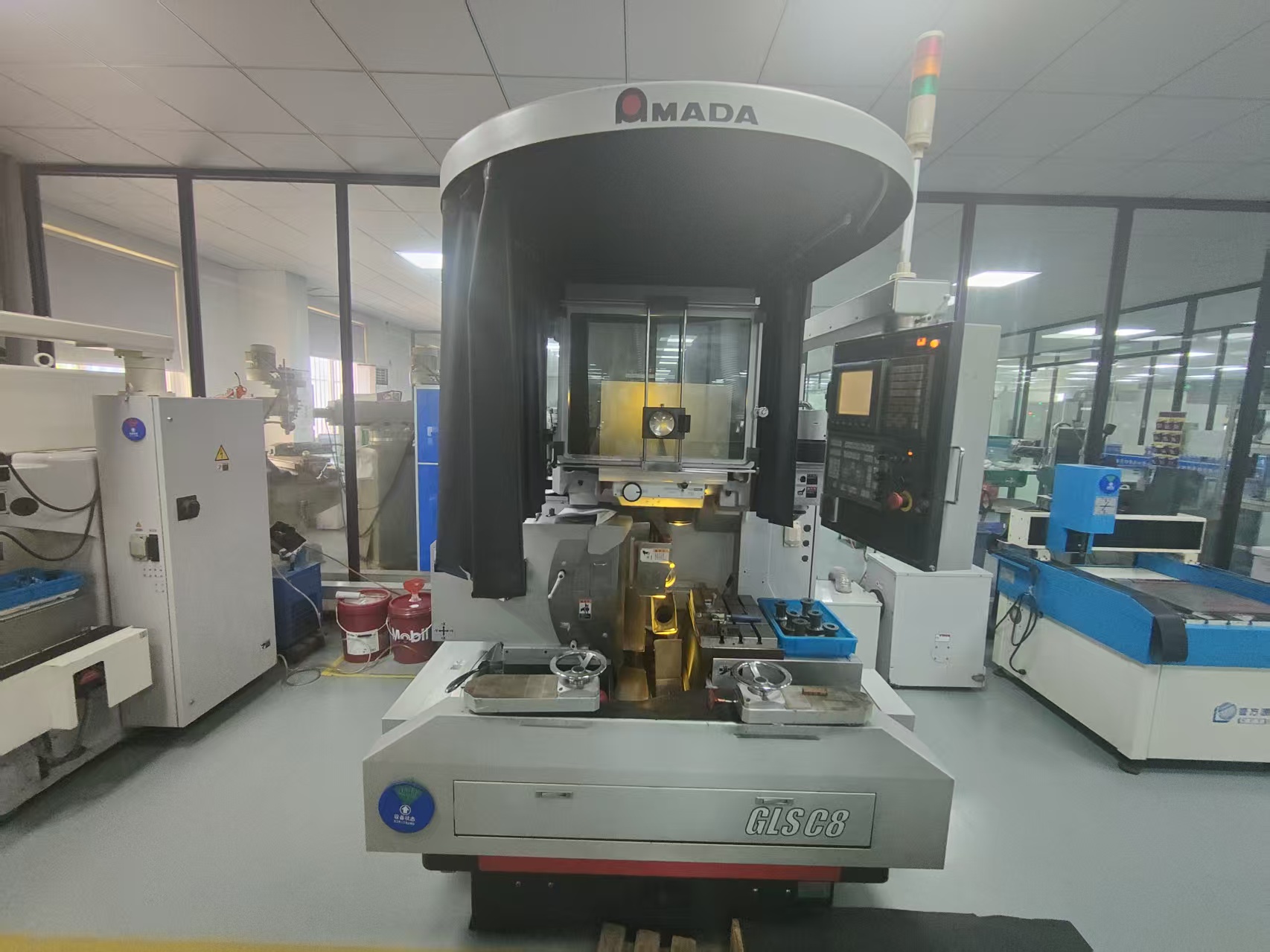
Lathes and other turning machines, with grinding, boring and radial drilling machines, cover shafts, bores, flanges and other rotational parts. CNC wire-cut handles profiles in conductive metals.
Fabrication for assemblies
CNC shearing, plate rolling and presses, with submerged-arc and gas-shielded welding, support complete machine assemblies that combine fabricated and machined parts.
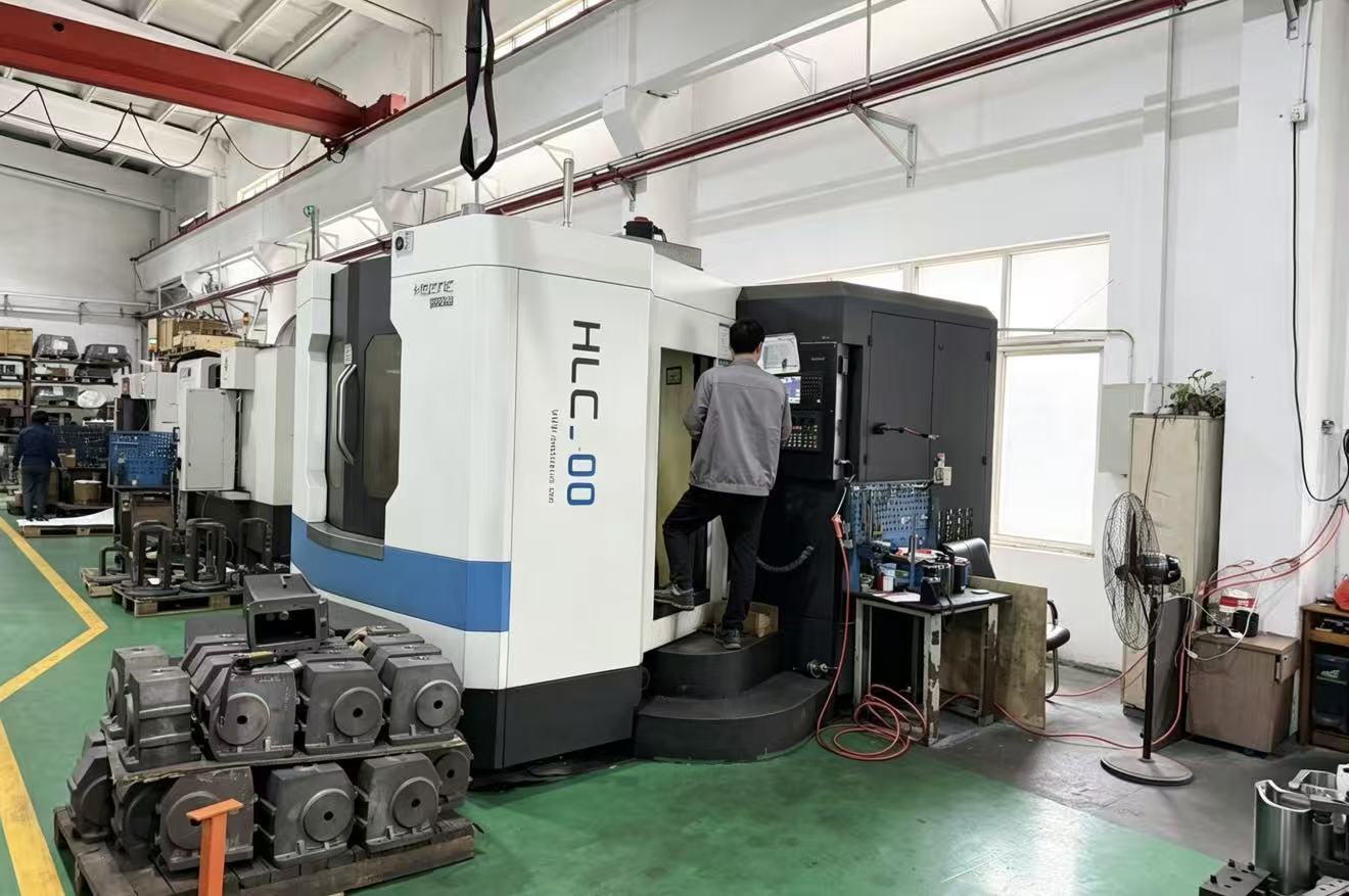
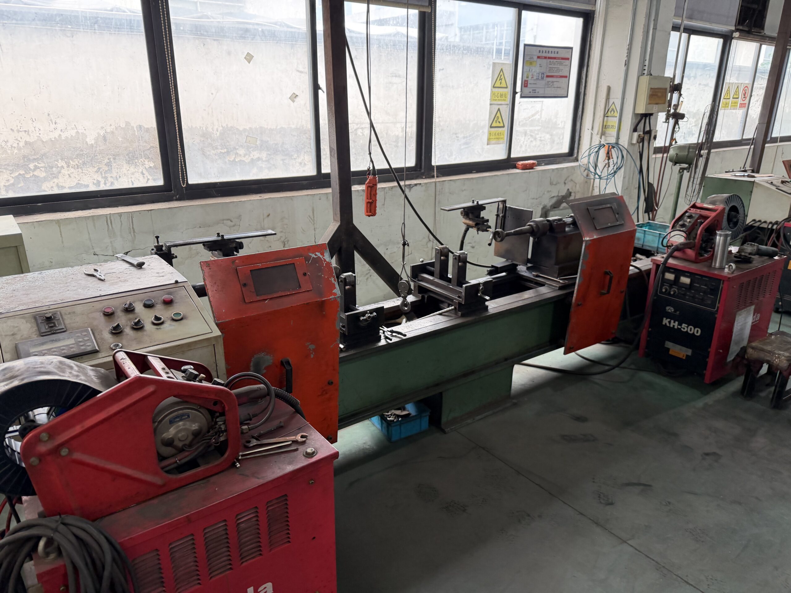
Parts we machine
- Complete machine assemblies
- Flanges and plugs
- Rollers and bent pipes
- Valve bodies
- Other custom-machined parts made to print
80% of our products are exported to Europe, Singapore, the United States, Australia and other regions. Drawings are quoted as written: we follow the general tolerance note in the title block, and where a drawing has none, ISO 2768-m applies to dimensions without their own tolerance.
Request a QuoteCNC Machining Materials We Work With
We machine carbon, alloy and stainless steels, nickel-based alloys and aluminum alloys. We also advise on material selection for high-temperature, corrosive and pressure service and hardness requirements.
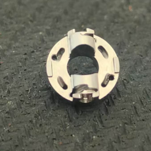
Carbon and low-alloy structural steels
GRADES
20#, 45#, Q235A, Q345D
Carbon and structural steels for general machine parts and welded structures. Q345D comes from GB/T 1591, the high-strength low-alloy structural steel standard, whose current edition is GB/T 1591-2018.
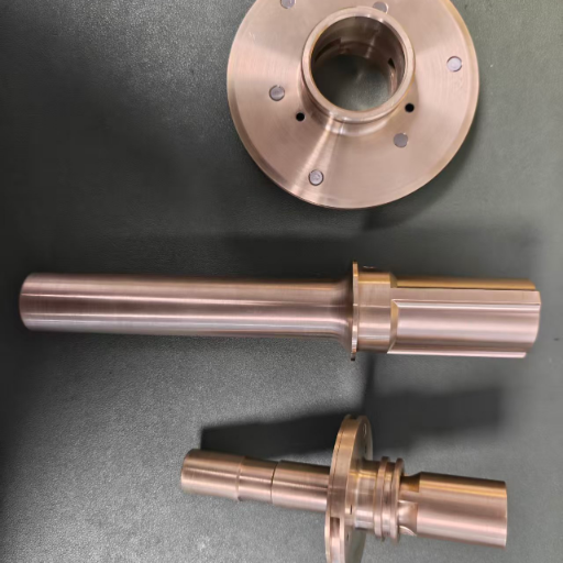
Alloy and bearing steels
GRADES
12CrMoV, 25CrMo, 42CrMo, GCr15
Chromium-molybdenum grades and the chromium bearing steel GCr15, for shafts and parts that are heat-treated before or after machining.
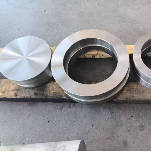
Stainless steels
GRADES
303, 304, 304L, 316, 316L, 321
303 has sulfur adjusted for machining; 316 and 316L carry 2–3% molybdenum for better resistance to chloride pitting; the L grades have reduced carbon for welded parts, and 321 is stabilized with titanium.
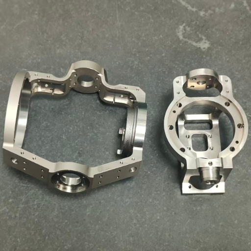
Nickel alloys, 904L & aluminum
GRADES
C276, 904L, nickel & aluminum alloys
C276 is a nickel-chromium-molybdenum alloy that withstands oxidizing and non-oxidizing acids and resists chloride pitting; 904L is a high-alloy austenitic stainless steel; aluminum alloys suit light parts.
Prototype lead times for these grades follow the order terms above; surface finishing, heat treatment and transit are quoted separately.
Review the material data section to compare cutting behaviour by grade.
Another material or grade?
Include the grade with your request, and we confirm the material and the machining route in the quotation for the part.
Quotes and Lead Times for Machined Parts
The final cost of a machined part is determined based on the drawing, the material, the quantity, and the process and inspection plan. There is no fixed price list for custom work, so your figure comes back in a written quotation.
What moves the price
- Material
- The raw cost and cutting speed are determined by the grade and stock size of the material.
- Geometry
- Deep pockets, thin walls and features on several faces add setups and machine time.
- Tolerances
- Dimensions tighter than the general class need slower finishing passes and more inspection.
- Quantity
- Setup and programming are spread across the batch. Thus, the per unit cost reduces with increase in quantity.
- Inspection & Docs
- The scope and prices of reports and certificates are in the quotation.
Lead times by order stage
- Quotes are returned within 2–3 working days of receiving your drawing, reviewed by an engineer.
- Prototype parts ship in 7–15 business days after drawing approval; surface finishing, heat treatment and transit are quoted separately.
- Small-batch orders ship in 7–15 business days after drawing approval.
- Production runs follow a schedule confirmed in the written quotation after sample approval.
Precision Machining:
Drawing to Delivery
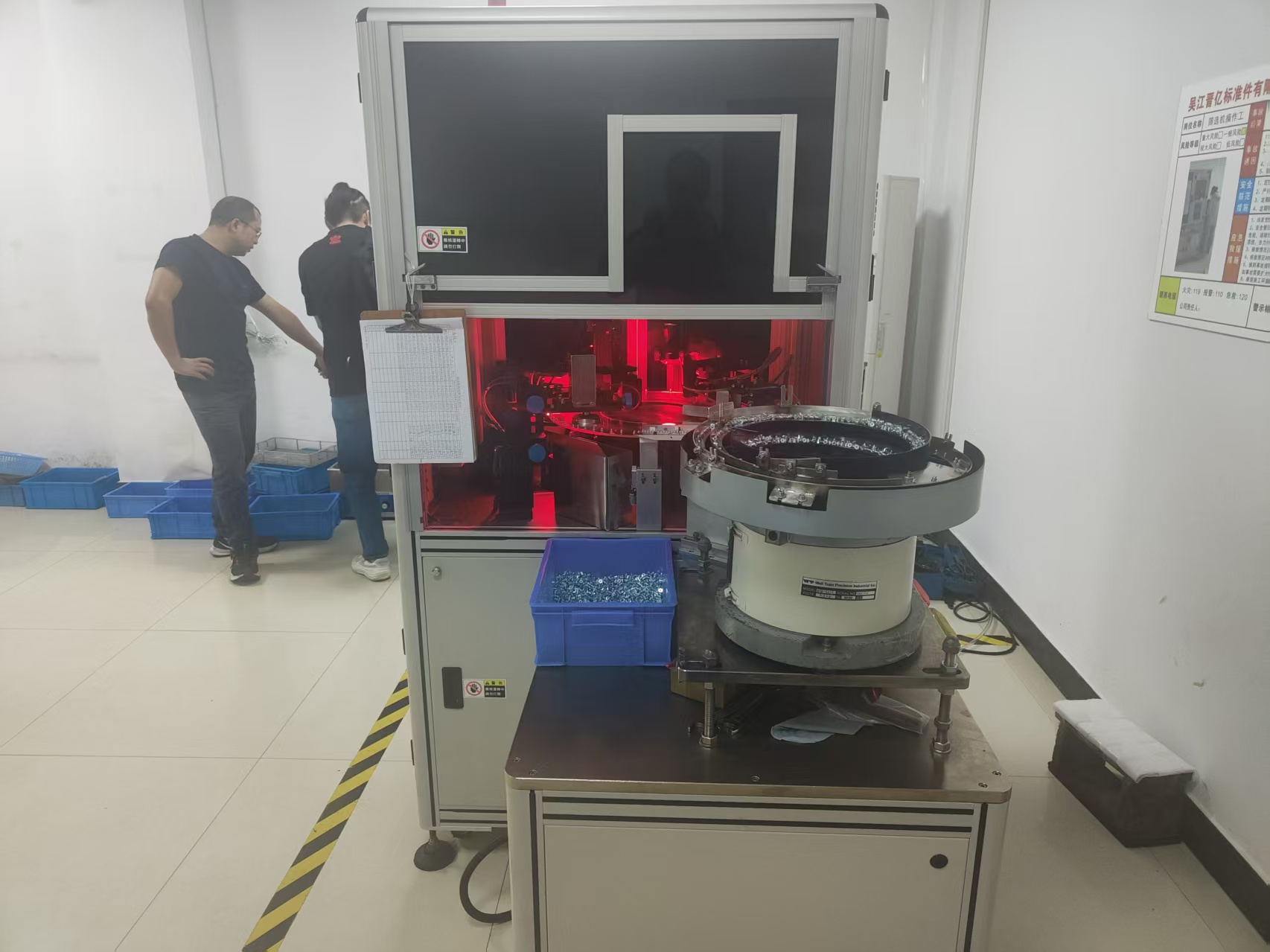
From initial engineering review to final CMM inspection, our process is optimized to balance tight tolerances, material integrity, and cost-efficiency.
Request
Share the part, quantity, material grade and tolerances via the quote form.
Review & Quote
Quotes are returned within 2–3 working days, fully reviewed by an engineer.
First-Article
First-article parts are available, with inspection scope clearly stated.
Machining
Parts are machined to the approved drawing at our Jiashan factory.
Inspection
Measured strictly against the drawing and agreed inspection scope.
Shipping
We ship EXW and FOB; alternative Incoterms available on request.
"Before we price a part, we check three things on the drawing: the material grade, the general tolerance note and every dimension that carries its own tolerance. If one of them is missing, our first reply is a question, not a figure."
Cost-Reduction Design Notes
| Design Feature | Specification | Cost Benefit |
|---|---|---|
| Internal corners | Radius larger than the cutter radius. | Standard end mill finishes without a second process. |
| Tolerances | Tight tolerances only on functional features. | Fewer dimensions require slow finishing passes. |
| Holes | Standard drill sizes, plain depth ≤ 3x diameter. | Standard drills clear chips and avoid special tooling. |
| Threads | Standard metric sizes, optimal thread depth. | Shorter tapping cycles using standard tools. |
Engineering Tools: ISO 2768 Standard
CNC Machining FAQs
What does a CNC machining knowledge library cover?
It covers the six areas a machined part passes through: materials, machining processes, tooling, programming, calculations and metrology. Each area has a hub page, two guides and at least one tool.
What is CNC machining?
In CNC machining, a subtractive manufacturing process, a computer numerical control program drives tools and cutters to remove material from a workpiece to create a part, from a single prototype to aerospace or automotive parts. The CNC fundamentals article follows a part from CAD to inspection.
How does a drawing become a CNC machined part?
CAD geometry becomes CAM tool paths and G-code, the machinist or CNC operator sets the workpiece and the work offset, and the machine cuts the part in one or more setups before it is measured. The guide to how material removal works covers each stage.
What does ISO 2768-m mean on a drawing?
It means every linear dimension without its own tolerance falls under the medium class of ISO 2768-1, for example ±0.3 mm on a 50 mm dimension. A second letter, as in ISO 2768-mK, points to ISO 2768-2, which ISO withdrew in 2021 and revised as ISO 22081:2021. A dimension that carries its own tolerance follows that tolerance instead.
Are calculator results ready to use as machine settings?
No. The speeds, feeds and tap drill sizes from the calculators are planning values, which means that the final settings depend on the rigidity of the machine, the condition of the material and the data of the tool maker.
Which CNC machines do you run?
We run 3-axis and 4-axis machining centers and imported 5-axis machining centers, alongside CNC wire-cut, lathes, milling, grinding, boring and radial drilling machines. CNC shearing, plate rolling, presses and welding equipment support fabricated assemblies.
What should I include in a CNC machining quote request?
Give us the part and the quantity, the material grade you need, the tolerances and finish requirements of the surfaces, and when you need the parts delivered. The RFQ input checklist provides a list of the details that shorten the quote.
Why do quotes for the same CNC part differ so much?
Quotes differ when suppliers read the same drawing differently, because material grade, tolerances, finishing, inspection and shipping terms all change the figure. Setup and programming are spread over the batch, so small quantities carry most of that cost. Compare quotes line by line on the same scope, and ask each supplier what it assumed where the drawing is silent.
How do I compare a China quote with a local machine shop?
Compare landed cost on the same drawing and quantity: the part price plus finishing, inspection documents, freight and duties. We ship EXW and FOB; other Incoterms on request.
Is it worth ordering a one-off CNC part from China?
It works when the drawing is complete and the lead time fits, because setup and programming make up most of the price of a single part. Prototype orders start from 1 piece; production quantities are confirmed in the quotation. We machine non-standard metal components from customer drawings or samples.
How long do prototype and batch parts take?
Prototype parts ship in 7–15 business days after drawing approval; surface finishing, heat treatment and transit are quoted separately. Small-batch orders ship in 7–15 business days after drawing approval. Production runs follow a schedule confirmed in the written quotation after sample approval.
Are my drawings kept confidential?
Your drawings are handled as confidential; an NDA is available on request before drawing review.



