
Get in touch with Zhenling Company



Updated September 2026
GD&T Symbols and Basics are rules and symbols that make every callout answer three questions: what geometry may vary, what reference establishes the part, and what evidence will decide acceptance. This guide separates the 12 current ASME geometric controls from two legacy symbols, then carries each callout from drawing intent to CNC quotation and inspection.
Key takeaway
Do not choose a GD&T symbol from the shape of a part alone. Start with the functional failure to prevent, define the datum relationship, state the governing standard edition, and agree how the tolerance will be measured and accepted.
Quick Reference
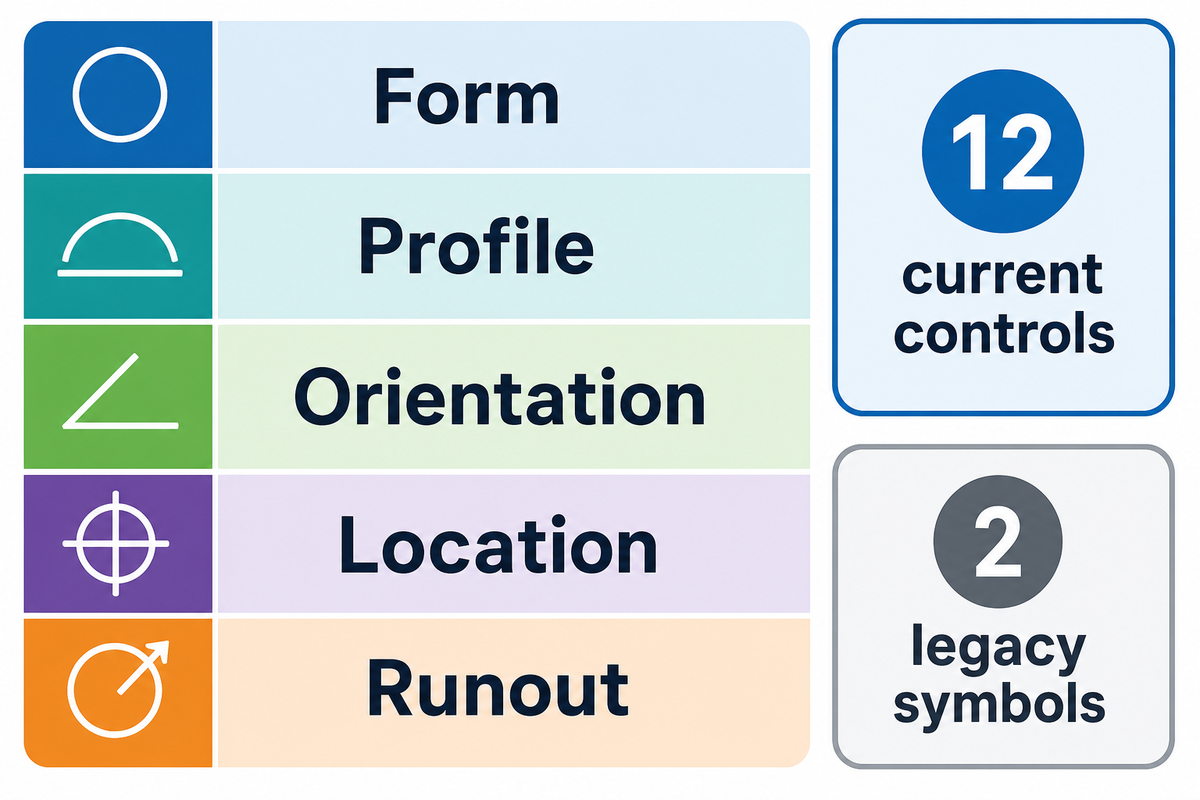
- The five control families are form, profile, orientation, location, and runout.
- This guide counts 12 current geometric characteristic controls under ASME Y14.5-2018.
- Concentricity and symmetry are shown as legacy controls as some older drawings may contain them.
- Check your drawing revision, the governing standard and edition, the datum scheme, scope of inspection, and the acceptance criterion.
What Is GD&T, and What Problem Does It Solve?
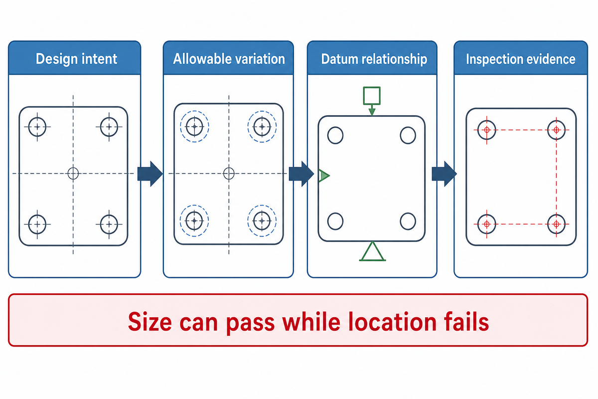
Geometric dimensioning and tolerancing, or GD&T, is a symbolic language for defining allowable variation in a part’s form, orientation, location, and runout. ASME describes Y14.5 as establishing symbols, rules, definitions, requirements, defaults, and recommended practices for dimensioning and tolerancing. The practical purpose is to communicate design intent in a form that design, manufacturing, and inspection teams can apply consistently.
Size and geometric tolerances satisfy different requirements. For example, a drawing may allow a hole diameter from 10.00 to 10.10 mm, yet that limit alone doesn’t fully state where the hole axis belongs. That isn’t sufficient information for the position of the hole axis. Position can define a cylindrical zone around the theoretically exact hole location. The hole can meet size and still fail location, or meet location and still fail size.
Function-first example
When a mounting plate rocks, controlling the distance from its surface to an edge won’t control surface form. Flatness may address rocking without a datum. If the same surface needs to be positioned square to a locating bore, the issue is the orientation relative to the bore-derived datum.
GD&T is most useful when the tolerance ties to assembly, sealing, alignment, motion, or interchangeability. An unnecessarily restrictive specification can require additional setup and inspection without reducing the risk of a functional failure. For more information, visit the metrology and drawing inspection resources.
GD&T Symbols Chart: 12 Current Controls and 2 Legacy Symbols
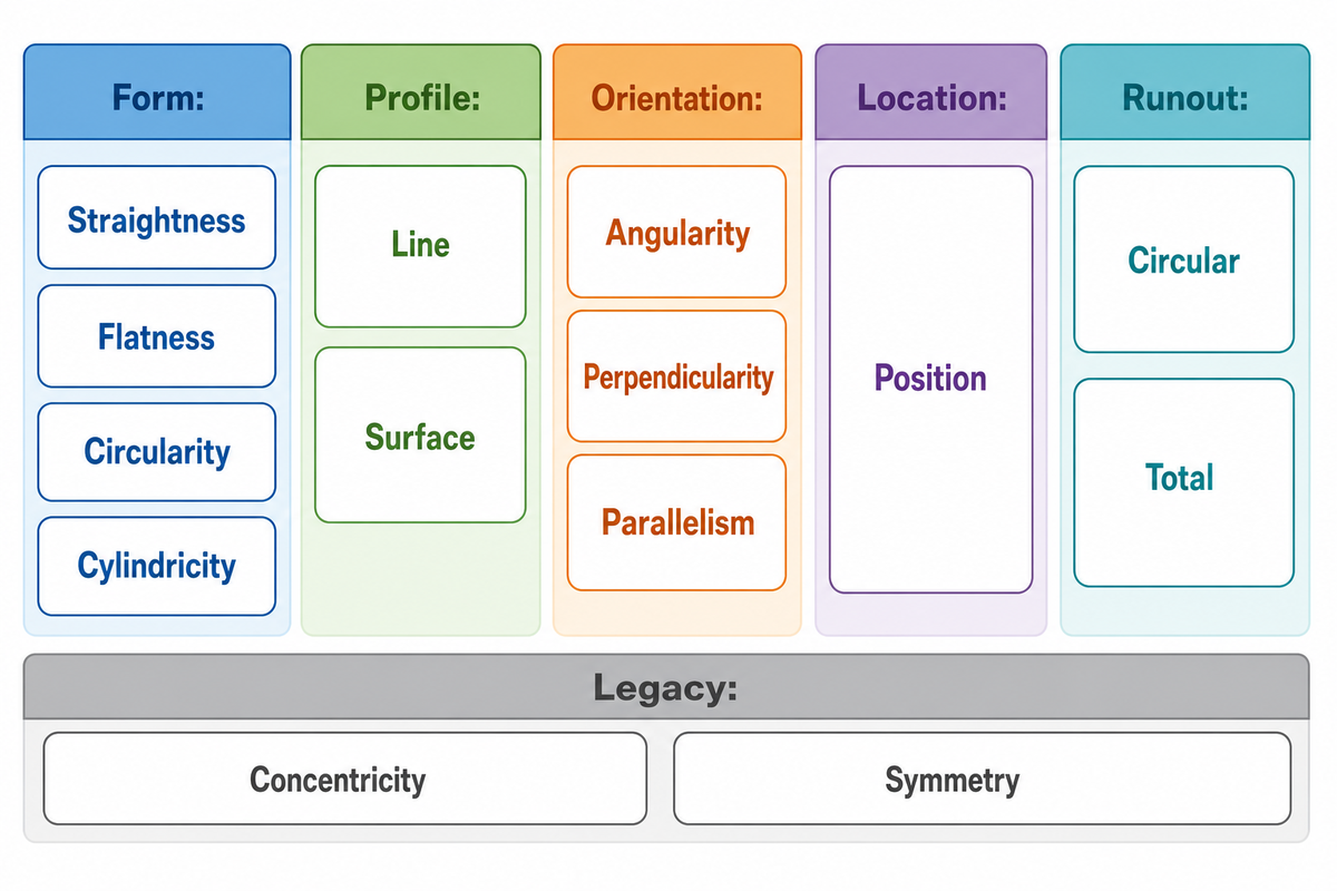
ASME lists Y14.5-2018 as reaffirmed in 2024. For practical reference, this guide groups the 12 controls remaining after the two documented removals into five teaching families: form, profile, orientation, location, and runout. That count and grouping are an editorial synthesis, not an enumeration stated on ASME’s catalog page. Maximum material condition and other similar modifiers are not additional geometric controls, nor is a family an additional symbol.
| Control type | Control | Tolerance-zone form | Datum? | Typical use | Typical verification route |
|---|---|---|---|---|---|
| Form | Straightness | Two parallel lines; cylindrical zone when an axis is controlled | No | Line element or derived median line | Indicator trace, form instrument, or coordinate data |
| Flatness | Two parallel planes | No | Sealing or mounting face | Surface plate and indicator, or coordinate measurement | |
| Circularity | Two concentric circles at each section | No | Round cross-section | Roundness instrument or section measurement | |
| Cylindricity | Two coaxial cylinders | No | Whole cylindrical surface | Form instrument or dense coordinate scan | |
| Profile | Profile of a line | Two-dimensional band normal to the true profile | Optional by requirement | Cross-section contour | Comparator, scan, or coordinate section |
| Profile of a surface | Three-dimensional boundary about the true profile | Optional by requirement | Complex surface or contour | Coordinate measurement or 3D scan | |
| Orientation | Angularity | Parallel planes, or a cylindrical zone, at a basic angle | Yes | Sloped face or axis | Sine setup, indicator, or coordinate measurement |
| Perpendicularity | Parallel planes or cylinder at 90 degrees to datum | Yes | Square face or axis | Square/indicator setup or coordinate measurement | |
| Parallelism | Parallel planes or cylinder parallel to datum | Yes | Opposed face or axis | Indicator sweep or coordinate measurement | |
| Location | Position | Usually cylindrical for an axis; parallel planes for a center plane | Yes | Hole, pin, slot, or pattern | Functional gage or coordinate measurement |
| Runout | Circular runout | Variation at each circular section during rotation | Yes | Rotating diameter or face | Indicator at defined sections while rotating |
| Total runout | Total surface variation during rotation and sweep | Yes | Entire rotating surface | Continuous indicator sweep or coordinate method |
Reading boundary: tolerance-zone descriptions are compact teaching summaries. Interpretation depends on the drawing standard, feature type, callout, and method of evaluation. Each verification process is typical, not universal.
Why Do Some GD&T Charts Show 14 or 16 Symbols?
Older charts often include concentricity and symmetry. A Mitutoyo presentation on the 2018 edition changes reports that ASME Y14.5-2018 removed their terms, symbols, and concepts. They still matter when reading legacy drawings governed by an older edition, but they shouldn’t be silently counted as current 2018 controls.
Counts increase when a chart combines controls with modifiers, datum symbols, basic dimensions, tolerance zones, projected tolerance zones, or subtypes. State the standard, edition, and counting rule before comparing charts. Substitution in an old drawing shouldn’t be treated as a modernization without the involvement of an engineer. The replacement should retain the original design requirement.
How to Read a Feature Control Frame from Left to Right
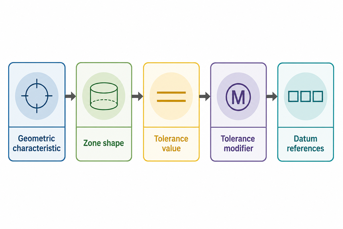
The feature control frame is a sequence and shouldn’t be considered as a bag of symbols. Read the compartments from left to right: geometric characteristic, zone shape if shown, tolerance value, tolerance modifier, then datum references in their stated order with any datum-boundary modifiers.
Illustrative frame
POSITION | ⌀0.20 | MMC | A | B(MMB) | C
This teaching shorthand means: control position; use a 0.20-diameter zone; apply maximum material condition to the controlled feature; reference A first, B second at a stated material boundary, and C third. The actual drawing must use the standard’s proper symbols.
- Name the control – decide whether the frame controls form, profile, orientation, location, or runout.
- Build the zone – read the diameter symbol, value, and any unequal or projected-zone instruction.
- Place each modifier – a modifier after the tolerance acts on the controlled feature; one after a datum reference acts on the datum boundary.
- Establish datum precedence – primary, secondary, and tertiary order is functional and not interchangeable.
- Define verification – agree alignment, sampling, evaluation, uncertainty, and the pass/fail rule.
Three warning signs deserve clarification: a diameter symbol used for a zone that isn’t cylindrical; a material condition modifier attached to something that isn’t a feature of size; or a datum letter that can’t be tied to an accessible, repeatable datum feature. The frame may appear compact, but its inspection program may remain undefined.
For feature control frame training, use this tool to build a feature control frame. This is a decoding aid. Using this tool doesn’t imply approval for a production drawing.
Datum Basics and the 3-2-1 Rule
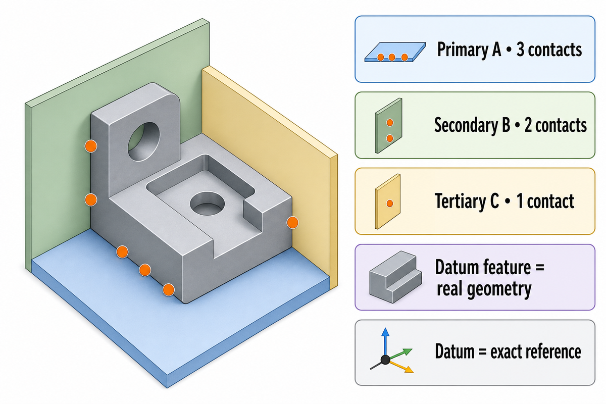
A datum feature is real part geometry; a datum is a theoretically exact reference derived from it; a datum reference frame is the ordered coordinate system established from selected datum features. NIST’s language distinguishes this scenario: an imperfect physical surface is either contacted or modeled. An inspection is used to establish an exact reference for evaluation.
For a stable prismatic part with planar datum features, the common 3-2-1 model explains how six rigid-body degrees of freedom are constrained. Three primary contacts restrict one translation and two rotations, while two secondary contacts restrict the other translation and rotation. Finally, one tertiary contact restricts the last translation.
| Datum level | Common planar contacts | What it contributes | Shop-floor check |
|---|---|---|---|
| Primary A | 3 | Seats the part and establishes the first plane | Does it rock, bridge burrs, or contact a warped zone? |
| Secondary B | 2 | Orients the part against a second plane | Is the feature accessible to fixture and inspection? |
| Tertiary C | 1 | Stops the last available translation | Does the contact represent assembly clocking? |
A datum surface that rocks or cannot repeat is a poor reference surface even if the letter sequence appears correct. Functional contact and inspection access need to be reviewed together.
Practical takeaway based on Dustin Smith, Quality Magazine, 2025
The 3-2-1 model describes a useful planar constraint. However, this shouldn’t be confused with a universal datum. Several features, such as cylindrical datums, patterns, datum targets, compliant parts, and material boundary applications, can define references in their own ways. If one of the primary contact surfaces rocks, then additional arbitrary fixture pressure won’t solve the problem; engineering must decide what contact means in the context of function.
Material Condition Modifiers Without the Jargon
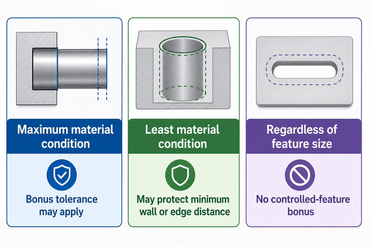
Maximum material condition, least material condition, and regardless of feature size describe how geometric tolerance relates to a feature of size. The most important beginner check is where the modifier appears. Placement after the tolerance value applies the modifier to the controlled feature. Placement after a datum reference concerns the datum feature’s simulated boundary and may permit datum mobility under the governing rules.
| Condition | Plain-language meaning | Controlled-feature effect | Do not assume |
|---|---|---|---|
| Maximum material condition | Most material: smallest hole or largest pin | May allow bonus tolerance as actual size departs from maximum material condition | That a datum modifier creates the same kind of bonus |
| Least material condition | Least material: largest hole or smallest pin | May protect minimum wall or edge distance as size changes | That it suits every assembly requirement |
| Regardless of feature size | Geometric limit applies independent of actual feature size | No controlled-feature bonus from size departure | That a printed symbol is always required; defaults depend on the edition |
Illustrative bonus-tolerance calculation
Suppose a hole has size limits of 10.00 to 10.10 mm and position is specified as diameter 0.20 mm at maximum material condition. For this internal feature, maximum material condition is 10.00 mm. If the measured hole is 10.06 mm, its departure is 0.06 mm.
Available position tolerance in this simplified example = 0.20 + 0.06 = diameter 0.26 mm. This example demonstrates arithmetic, not a production acceptance result. Feature size, form, virtual-condition boundary, datum effects, and the governing edition still need to be assessed.
Apply these modifiers only where the standard permits, generally to applicable features of size. Do not attach maximum or least material condition to a general surface-control value merely because more tolerance is desired. If a datum is referenced at a material boundary, state the simulator and evaluation methodology, rather than referring to the resulting ‘datum mobility’ as ‘bonus tolerance’.
Choose the Control from the Failure Mode, Not the Part Shape
A tolerance is meaningful only if its zone blocks the relevant failure. A round shaft may require circularity, cylindricity, position, perpendicularity, or runout, depending on whether the concern is local out-of-roundness, full-surface form, axis location, axis orientation, or rotation about a datum axis.
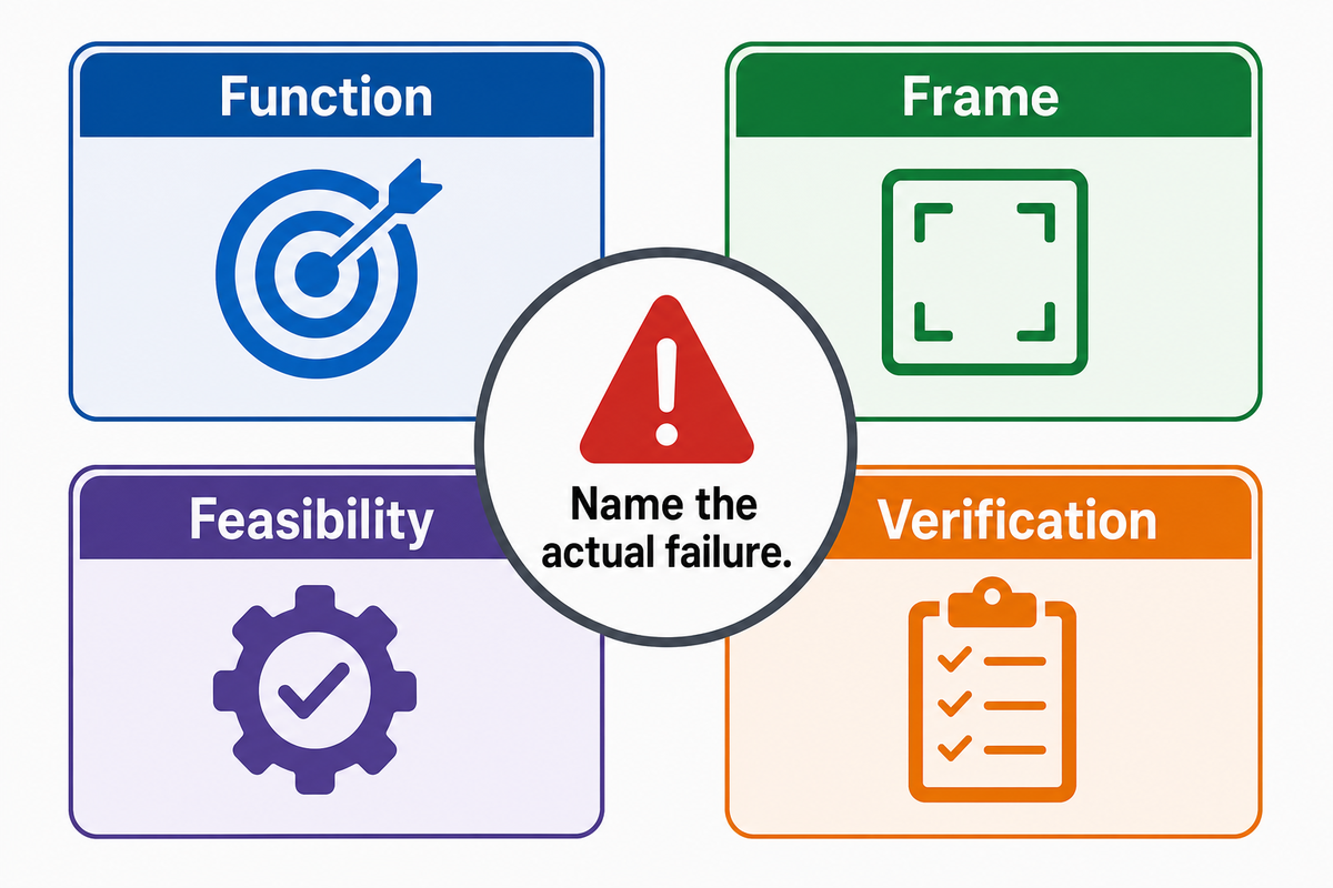
The 4-Lens GD&T Drawing Review
- Under Function, name the actual failure: rocking, tilt, leakage, mislocation, contour interference, or rotational wobble.
- Through the Frame lens, check whether the characteristic, zone shape, modifier, and datum order express that function.
- For Feasibility, confirm the datum and controlled feature can be machined, fixtured, and accessed without distortion.
- Under Verification, specify alignment, sampling, evaluation, uncertainty, report fields, and the acceptance rule.
| Failure to prevent | First control to consider | Datum need | Common wrong choice | When not to use it |
|---|---|---|---|---|
| Surface rocks on its own | Flatness | None | Parallelism to an unrelated datum | When orientation to assembly is the real need |
| Face tilts in assembly | Parallelism, perpendicularity, or angularity | Yes | Flatness alone | When only surface form matters |
| Hole or pin misses mating pattern | Position | Usually yes | Plus/minus coordinates alone | When boundary or location is not the functional issue |
| Complex contour interferes or leaks | Profile of a surface | Depends on whether location/orientation is controlled | Many disconnected coordinate dimensions | When a simpler form or size control defines function |
| Rotating diameter wobbles at one section | Circular runout | Yes, datum axis | Circularity | When full-surface variation must be limited |
| Entire rotating surface varies | Total runout | Yes, datum axis | One circularity check | When only a single section matters |
This control starts the design review process. This control isn’t a substitute for another design review. The control may be valid and unnecessarily strict, redundant with another callout, or disconnected from the mating interface. It’s best to ask what will fail first, then develop a tolerance that manufacturing and inspection can manage.
Four Worked Examples: Flatness, Position, Profile, and Runout
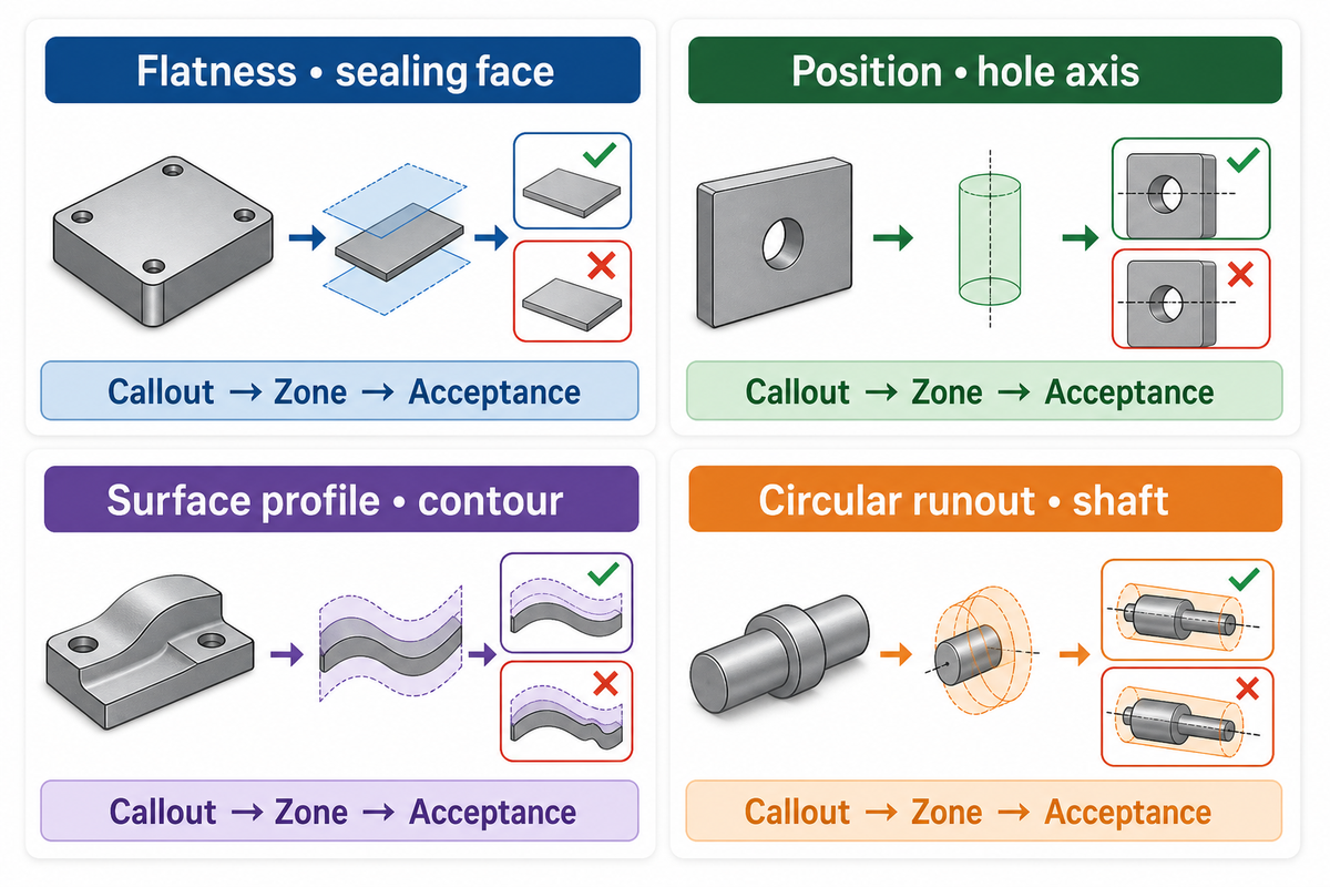
These examples are educational. They don’t explain Zhenling’s production capabilities or describe a universal inspection procedure. They show the path from a callout to an acceptance question.
1. Flatness on a sealing face
Callout: Flatness is specified at 0.05 mm on one face.
Zone: Whole controlled surface between two parallel planes 0.05 mm apart, with no datum reference.
Usual method: choose a surface sampling pattern using a surface plate, indicator or coordinate system. Then assess the sampled surface using the agreed upon method.
Acceptance question: Did the surface remain within the 0.05 mm zone? Flatness doesn’t control the angle of the face with respect to other features.
2. Position of a hole
Callout: hole position diameter 0.20 mm relative to A, B, and C, regardless of feature size. Zone: the measured hole axis must remain within the stated cylindrical zone around its basic location. For a simplified 2D teaching check, a hole intended at X 25.00, Y 15.00 mm and measured at X 25.04, Y 14.97 mm has diametrical coordinate deviation of 2 × √(0.04² + 0.03²) = 0.10 mm. That coordinate result is within 0.20 mm, subject to the stated assumptions.
Actual acceptance depends upon the datum reference frame, feature axis extraction, depth, sampling, size result, and drawing rules. Use the 2D true position calculator to perform clear coordinate calculations, not as a substitute for complete geometry assessment.
3. Surface profile on a machined contour
Callout: surface profile 0.30 mm relative to A, B, and C.
Zone: the controlled contour must stay inside a three-dimensional boundary based on the true profile and the callout’s disposition.
Typical route: align to the datum reference frame, sample enough of the functional contour, compare points or a scan to the nominal model, and report the evaluation method.
Acceptance question: does the evaluated surface remain within the defined profile zone, including the areas most likely to contact the mating part?
4. Circular runout on a shaft diameter
Callout: circular run-out 0.03 mm relative to datum axis A.
Zone and Test: rotate the part about the established datum axis and monitor indicator reading for each circular section.
Acceptance question: does each checked section remain within 0.03 mm under the agreed setup? One section isn’t conclusive for runout of the entire surface. Rotation on centers that don’t reproduce datum A can answer the wrong question.
From GD&T Drawing to CNC Quote: The Cost and Risk Handshake
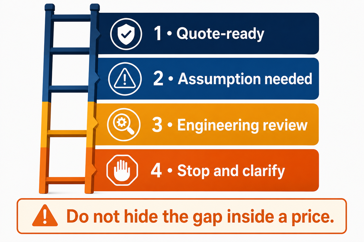
A responsible CNC quote includes more detail than a PDF with tolerances. Two suppliers can bid on the same geometry, but can come back with different quotes. This is because one supplier may assume a sample inspection with a standard report, and the other supplier may include a complete coordinate measurement program, fixture development, uncertainty review, and complete reports. Define the inspection scope in order to compare quotes.
| Level | Drawing condition | Quotation action | Buyer risk |
|---|---|---|---|
| 1: Quote-ready | Edition, revision, datums, callouts, sampling, report, and decision rule are stated | Price the stated route and list assumptions | Low interpretation risk |
| 2: Assumption needed | Function is clear, but sample size or report depth is open | Quote named options | Prices may not be comparable |
| 3: Engineering review | Unstable datum, questionable modifier, inaccessible feature, or uncertain method | Resolve the callout before final price | Rework or dispute risk |
| 4: Stop and clarify | No governing system, conflicting frames, or no feasible acceptance route | Do not hide the gap inside a price | High commercial and quality risk |
According to the company-provided manufacturing brief, Shanghai Zhenling Hardware was established in 2006 and operates CNC turning, milling, grinding, boring, drilling, wire-cut electrical discharge machining, and 3-, 4-, and 5-axis machining equipment. The company’s material experience includes carbon and alloy steels, stainless steels, nickel-based alloys and aluminum alloys. These details don’t confirm that all tolerances, materials, and inspection methods are available for each job.
GD&T CNC RFQ Checklist: send the same fields to every bidder
| Field | What to provide | Why it changes the quote | Evidence at release |
|---|---|---|---|
| Drawing control | Revision, 3D model, standard and edition | Fixes the interpretation baseline | Approved drawing package |
| Part scope | Material, heat treatment, finish, quantity, and lot size | Changes process, distortion, setup, and sampling | Material and process records as specified |
| Functional controls | Critical frames, mating features, and failure to prevent | Directs process and engineering review | Ballooned report links |
| Datum setup | Feature sequence, targets or simulators, and access limits | May require fixture or special alignment | Setup and alignment record |
| Inspection scope | Method, sample size, fitting rule, and report format | Changes programming and measurement time | Raw or summarized results as agreed |
| Acceptance | Uncertainty policy, decision rule, and disposition owner | Prevents boundary disputes | Signed acceptance package |
Use the GD&T drawing review checklist before comparing custom CNC machining services.
Have a GD&T-controlled part to quote?
Please send your drawing revision, the standard version, material, quantity, the critical callouts, the inspection deliverables, and the required report format for acceptance. The inspection team shouldn’t make assumptions; the plan should answer who resolves an indeterminate or disputed result.
Match Each GD&T Control to Inspection Evidence
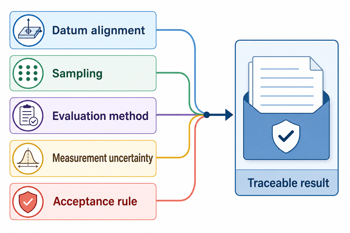
“Inspected on a coordinate measuring machine” isn’t an acceptance plan. The machine name doesn’t disclose how datums were established, which points were sampled, which fitting algorithm was used, how filtering or outliers were handled, what uncertainty applies, or which rule converts the result into acceptance.
NIST research demonstrates why planar datum details matter. Errors can occur when points are sampled non-uniformly and an unweighted fitting technique is used. Nonuniform sampling and unweighted fitting can create erroneous results from the sample points. More points don’t substantiate a claim unless the locations of the points and the evaluation technique approximate the feature under consideration.
| Family | Typical method | Evidence that must be explicit | Method limit to flag |
|---|---|---|---|
| Form | Form instrument, indicator, or coordinate data | Support condition, sampling path, filter/fitting rule, maximum result | Sparse points may miss local peaks |
| Profile | Coordinate measurement, scanning, or comparator | Datum alignment, nominal model revision, sampling density, zone disposition | A scan can still use the wrong alignment |
| Orientation | Indicator setup or coordinate measurement | Datum simulator, constrained degrees, evaluated feature, tolerance result | Fixture reference may not reproduce the datum |
| Position | Functional gage or coordinate measurement | Feature size, datum setup, axis/center extraction, modifier effects, result | A 2D center check may miss axis tilt |
| Runout | Indicator during controlled rotation | Datum-axis realization, section or sweep path, rotation method, peak variation | Machine centers may not equal the specified datum axis |
For every route, add equipment identification and calibration status, relevant environmental conditions, measurement uncertainty where required, and the agreed acceptance rule. A first-article report shall connect the ballooned characteristic to its drawing revision, measured result, units, disposition, and a traceable record.
The inspection plan should also say who resolves an indeterminate or disputed result. This particular detail is important when approaching a tolerance limit: repeating the measurement with a different alignment or with a different point pattern, following the observation of the initial measurement result, isn’t neutral, unless a different measurement method was previously agreed upon.
What Is Changing: Make the Standard Edition Part of the Contract
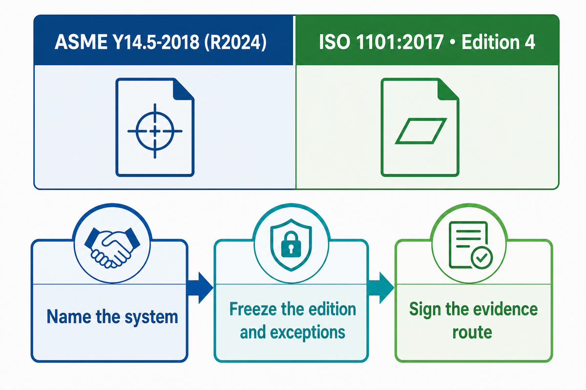
ASME currently displays Y14.5-2018 (R2024), while ISO lists ISO 1101:2017, edition 4, as current and confirmed in 2022; the contract should name the governing system and edition. These are different systems. Similar looking marks do not allow a supplier to combine rules.
| Contract field | ASME route | ISO route |
|---|---|---|
| System and edition | State ASME Y14.5 edition, including legacy drawing status | State ISO 1101 edition and related invoked standards |
| Edition-sensitive items | Flag legacy concentricity/symmetry and modifier defaults | Flag ISO-specific notation, defaults, and referenced specifications |
| Acceptance | State the agreed contractual decision rule | Apply ISO conformity rules only within their stated or adopted scope |
3-Step Standard Edition Handshake
- First, name the system: ASME or ISO; do not write only “GD&T applies.”
- Next, freeze the edition and exceptions: record the year, drawing revision, legacy controls, and contractual departures.
- Finally, sign the evidence route: agree datum realization, sampling, evaluation, uncertainty treatment, report, and acceptance rule before the purchase order.
ISO 14253-1:2017 addresses measurement uncertainty in conformity decisions for ISO geometrical product specifications and quantity-valued characteristics. Its public scope is not permission to impose it automatically on every ASME drawing. For an ASME-controlled contract, use an ISO 14253-1 decision rule only if the parties explicitly adopt it and resolve any interface questions.
Training can’t be assumed. A 2025 survey of 67 instructors in the United States post-secondary engineering and engineering-technology programs reported that dimensioning and tolerancing was mandatory in curricula for about three quarters of students, while fewer than one third consistently received GD&T instruction. Because the sample was self-selected, treat the findings as a warning about communication gaps, not a population estimate.
Frequently Asked Questions
Can you explain GD&T in a simple way?
GD&T is a drawing language for limiting how much a real feature may depart from ideal geometry. A symbol names the variation, a feature control frame gives the limit and references, and an inspection plan decides how conformance is shown. It supplements size dimensions by describing form, orientation, location, profile, or rotation.
What are the basic symbols used in GD&T?
Under the ASME Y14.5-2018 counting convention used here, the 12 current controls are straightness, flatness, circularity, cylindricity, profile of a line, profile of a surface, angularity, perpendicularity, parallelism, position, circular runout, and total runout. Concentricity and symmetry belong in a separate legacy note for older editions. The governing drawing edition controls how those legacy symbols are interpreted.
What are datums?
Datums are theoretically exact references established from selected physical datum features. In an ordered datum reference frame, they orient and locate the part so another feature can be evaluated consistently. The datum feature is the imperfect surface, bore, width, or pattern on the part; the datum is the exact reference derived under the applicable rules.
Is learning GD&T difficult?
The vocabulary is manageable. The harder task is connecting a frame to function and measurement. Learn the five families first, then datum order, zone shape, modifier placement, and worked inspection examples.
How much deviation from the ideal axis is acceptable?
There’s no universal allowable axis deviation. Read the feature control frame. Position may place the axis inside a cylindrical tolerance zone, while perpendicularity may limit its orientation relative to a datum. The permitted amount can also depend on actual feature size when an allowed material condition modifier applies. Acceptance therefore requires the tolerance value, zone shape, feature-size result, datum setup, axis extraction method, sampling depth, fitting or evaluation method, measurement uncertainty where required, and governing edition. A center-point offset alone can’t answer every axis question.
Does every GD&T control require a datum?
No. Form controls such as flatness, circularity, and cylindricity normally control a feature itself without a datum. Orientation, position, and runout require a reference relationship. Profile can control form without datums or include orientation and location through datum references.
Should a drawing use ASME Y14.5 or ISO 1101?
Use the system required by the customer, industry, contract, and engineering organization. Either can communicate geometric requirements, but they aren’t interchangeable rulebooks. Name the system and edition on the drawing, then resolve cross-system exceptions before quotation and production.
References & Sources
- ASME Y14.5 Dimensioning and Tolerancing current edition/status and scope.
- ISO 1101:2017 geometrical tolerancing standard page and status.
- ISO 14253-1:2017 conformity decision rules and stated ISO GPS scope.
- NIST, The Mathematics of Dimensional Metrology datum and datum-reference terminology.
- NIST, Planar Datum Establishment sampling and fitting implications.
- ASME, Introduction to Geometric Dimensioning and Tolerancing official teaching structure for current characteristic families.
- Mitutoyo, ASME Y14.5-2018 Changes educational summary of removed legacy controls.
- Quality Magazine, Common GD&T and Datum Pitfalls signed practitioner review.
- ASME Open Journal of Engineering, The Current State of Dimensioning and Tolerancing Pedagogy 2025 publisher version hosted by Purdue University.
Editorial boundary: examples are educational and use stated assumptions. The released drawing, governing standard edition, customer requirements, and agreed inspection plan control production acceptance. Company details are based on the manufacturer-provided brief unless otherwise linked.