Get in touch with Zhenling Company


Reviewed by the cnc.zhenlingmetal.com technical team | Updated September 2026
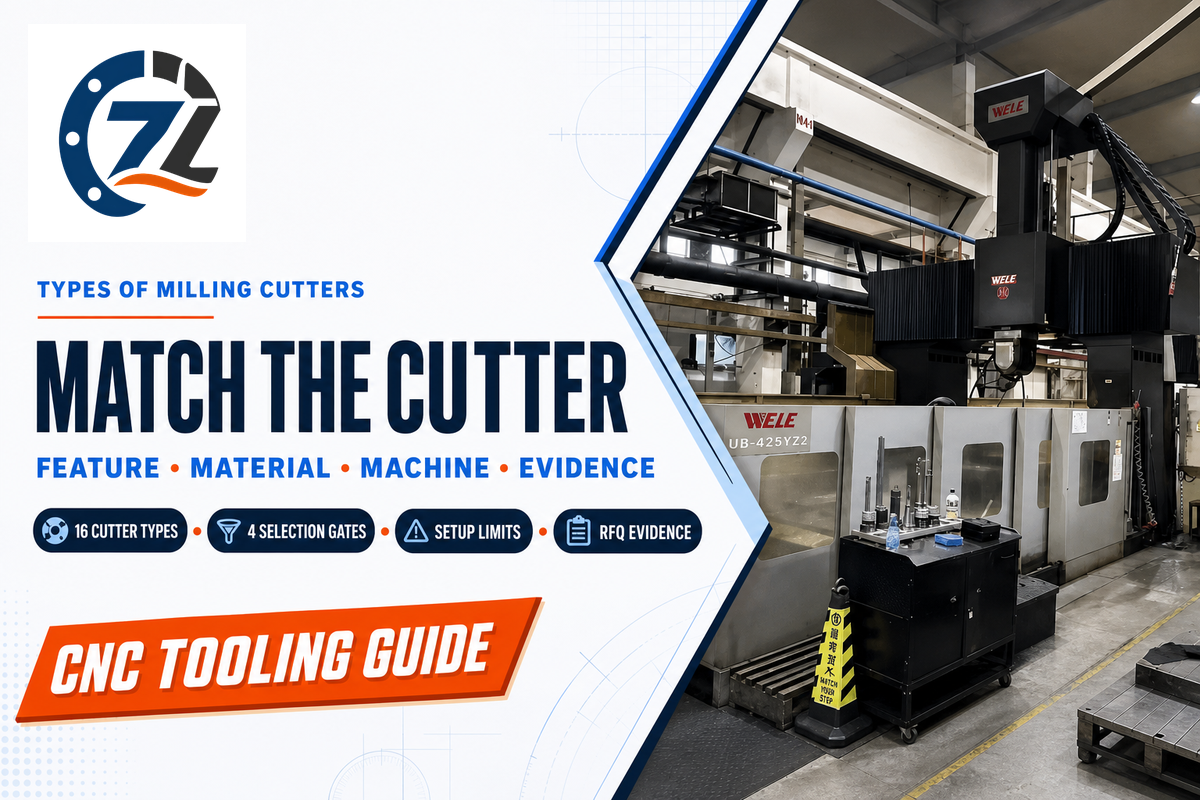
Types of Milling Cutters are best compared by the feature to be machined and the milling machine envelope needed to create it. This guide classifies the tool based on the cutting tool family, the edge profile, the tool’s construction, and the tool material. It also describes checks a design, process, or quality engineer, as well as a buyer who releases a job to be machined, is expected to make before accepting a machining job.
Key takeaway
Choose the family from the feature and access path, but screen machine power, spindle interface, rigidity, reach, coolant, and chip escape at the same time. Then choose profile, flute geometry, construction, substrate, coating, and inspection evidence.
Quick Reference
- End mills are milling cutters used for pockets, shoulders, contours, and many slots.
- Face mills generate broad faces; side-and-face, slab, and shell cutters address wider peripheral work.
- Dedicated-profile cutters create T-slots, keyseats, dovetails, chamfers, threads, gears, or formed profiles.
- Solid, modular, and indexable describe construction, not the feature family.
Quick Answer: Match the Feature and Machine Envelope Together
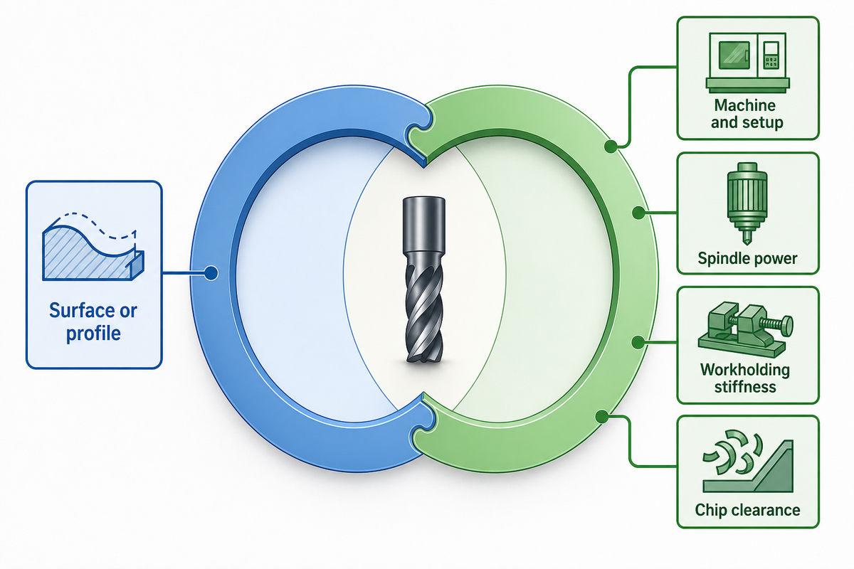
Start by considering the surface or profile the drawing requires, and then check whether the machine as well as the setup can potentially support the expected cutter. A suitable cutter family can still fail when spindle power, holder interface, workholding stiffness, overhang, coolant delivery, or chip clearance cannot support the cut.
This parallel screen eliminates two common mistakes. The first is selecting a tool from a catalog name only. The second is selecting a tool which appears to be aggressive and productive, but finding out that the machine can’t deliver constant torque, or the setup/fixture can’t withstand the cutting load. Compatibility of features enables the machining idea. Compatibility of the system decides if the route is possible.
This chart covers conventional CNC milling operations, including plain milling and slot milling, only. This chart doesn’t attempt to address micro-milling constraints. In micro-milling, the edge radius, minimum chip thickness, runout and cutting tool scale effects may entirely change the mechanism of cutting. Use this chart as a vocabulary framework to check the process of micro-milling after referring to micro-tool data and trials.
How Milling Cutters Are Classified
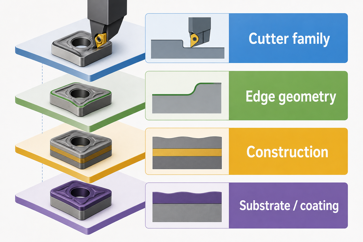
Useful classification separates four layers: family, edge geometry, construction, and cutting material. “End mill,” “ball nose,” “indexable,” and “carbide” all answer different questions. Combining any two in one list makes people think two tools are the same, when in fact, they’re usually different in how they’re accessed, what their body architecture is, what the shape of their edges is, or what workpiece materials they can cut.
Types of Milling Cutters Used in the Machining Process
| Layer | Question answered | Examples | Do not confuse with |
|---|---|---|---|
| Cutter family | What feature or surface can it reach? | End, face, T-slot, thread, gear | Substrate |
| Edge geometry | What contour and chip path does it create? | Square, ball, corner-radius, roughing | Body construction |
| Construction | How are the body and cutting edges arranged? | Solid, modular, indexable | Operation |
| Substrate/coating | How does the edge resist heat, wear, and shock? | HSS, carbide, coated carbide | Feature family |
“This publication was last reviewed and confirmed in 2024.”
ISO lifecycle page for ISO 11529:2013, the designation system for milling cutters
That confirmation makes ISO 11529 useful for designation context, but it does not select a tool for a particular drawing. By this classification, the construction and dimensions of the tool can be indicated, but the engagement of the tool, the holder, the workpiece material, and the acceptability evidence are all the responsibility of the machining process planning.
Feature-to-Cutter Decision Matrix: 16 Common Types
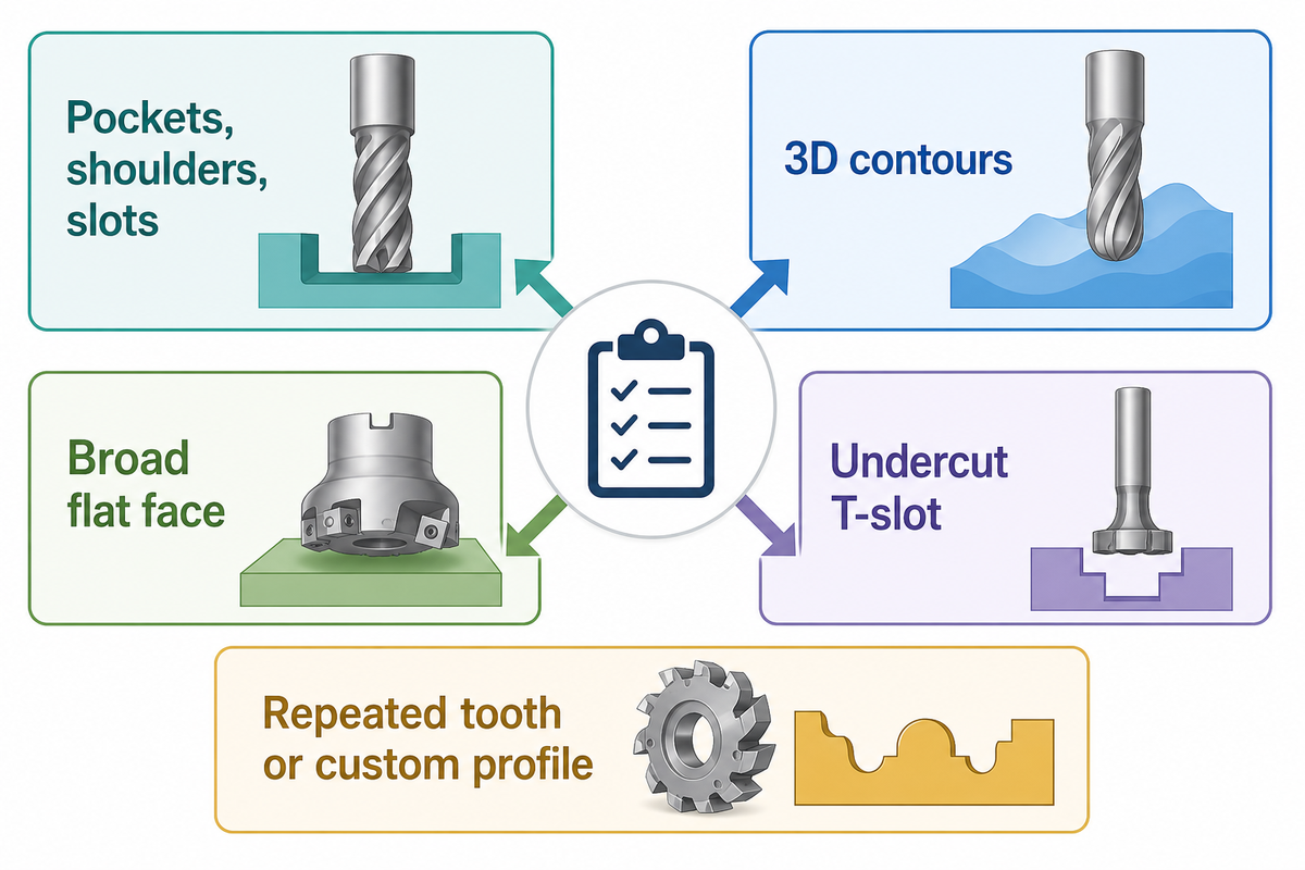
These 16 families are classified based on the features they can produce; they aren’t ranked based on a claim of relative speed. Read across to the limitation and release-evidence columns to see where a geometrically correct tool may still be a poor production choice.
Basic Milling, Slot Milling, and CNC Milling
| Cutter type | Primary feature | Why it fits | Limitation to check | Release evidence |
|---|---|---|---|---|
| Square end mill | Pockets, shoulders, slots | Flat bottom and near-square corner | Internal corner radius and chip escape | Pocket depth, corner radius, floor finish |
| Ball-nose end mill | 3D contours | Rounded tip follows changing surfaces | Low effective cutting speed near the tip | Scallop and surface-finish plan |
| Corner-radius end mill | Shoulders with a fillet | Stronger corner than a sharp square edge | Radius must match the drawing allowance | Corner-radius inspection |
| Roughing end mill | Bulk removal | Serrated edges divide chips and load | Usually needs finishing allowance | Stock allowance after roughing |
| Tapered or barrel cutter | Deep walls or 5-axis contours | Geometry supports reach or larger contact radius | Toolpath and collision dependence | Simulation and surface check |
| Face mill | Broad flat face | Multiple edges sweep a wide surface | Power, insert runout, interrupted entry | Flatness and finish record |
| Fly cutter | Flat face, light-duty or special setup | Single-point sweep is simple to set | Balance, guarding, and low edge count | Setup approval and finish check |
| Shell mill | Faces and shoulders | Arbor-mounted body covers larger diameters | Arbor interface and body clearance | Interface and runout record |
| Slab mill | Wide surface by slab milling | Teeth act around the circumference | Arbor support and machine layout | Arbor/setup verification |
| Side-and-face cutter | Deep slot or side surface | Cuts on circumference and sides | Side clearance and arbor deflection | Slot width and side finish |
| T-slot cutter | Undercut T-slot | Head enters through a narrower neck | Neck access, reach, bending, chip exit | Neck and undercut dimensions |
| Woodruff keyseat cutter | Semicircular keyseat | Disk profile matches the seat form | Cutter width and entry path | Width, depth, and location |
| Dovetail or angle cutter | Angled undercut | Fixed included angle creates the flank | Entry slot, angle, and tip fragility | Angle and virtual-width check |
| Chamfer mill | Chamfer or deburred edge | Angled edge controls bevel geometry | Tip condition and programmed depth | Chamfer width and angle |
| Thread mill | Internal or external thread | Helical interpolation generates the thread | Pitch compatibility and machine motion | Gage or specified thread report |
| Gear or form cutter | Repeated tooth or custom profile | Edge embodies a defined form | Profile standard, indexing, wear | Profile and pitch inspection |
This table should help you prepare a short list of candidates, but it isn’t intended to provide machining parameters. Engagement, grade, coating, holder, workpiece condition, and machine dynamics will still need to be considered. A cutter feature shortlist will help you organize these inputs before you even contact a supplier.
End Mill Profiles for Pockets, Shoulders, and 3D Contours
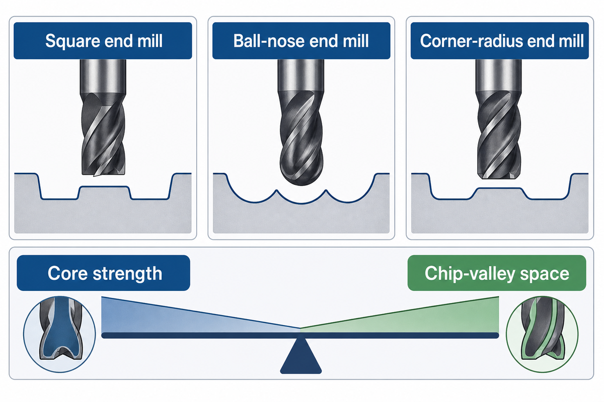
The end-mill profile determines the contour left behind, while flute count changes core strength and chip space. A square end mill favors flat surfaces and shoulders, a ball-nose end mill follows freeform surfaces, and a corner-radius end mill protects the cutting corner when the drawing allows a fillet.
More flutes don’t automatically result in better performance. While the number of teeth can increase available engagement and strengthen the tool’s core, additional flutes also decrease chip-valley space. Restricted chip evacuation in deep slots or in gummy materials can result in chip recutting, increased temperature, poor surface finish, and edge damage prior to reaching the theoretical tool capability.
≤3 flutesUF lab guidance for full-slotting non-ferrous work, not a universal standard
4 checksprofile, flute space, reach, and holder/runout before release
Treat the three-flute example as conditional local instruction. Don’t interpret this as a firm purchase order. Radial engagement, tool diameter, helix, coolant or air provision, holder condition, and machine capability can affect the answer. For a deeper analysis, refer to the end mill flute trade-off guide.
Face, Shell, Slab, Side-and-Face, and Fly Cutters
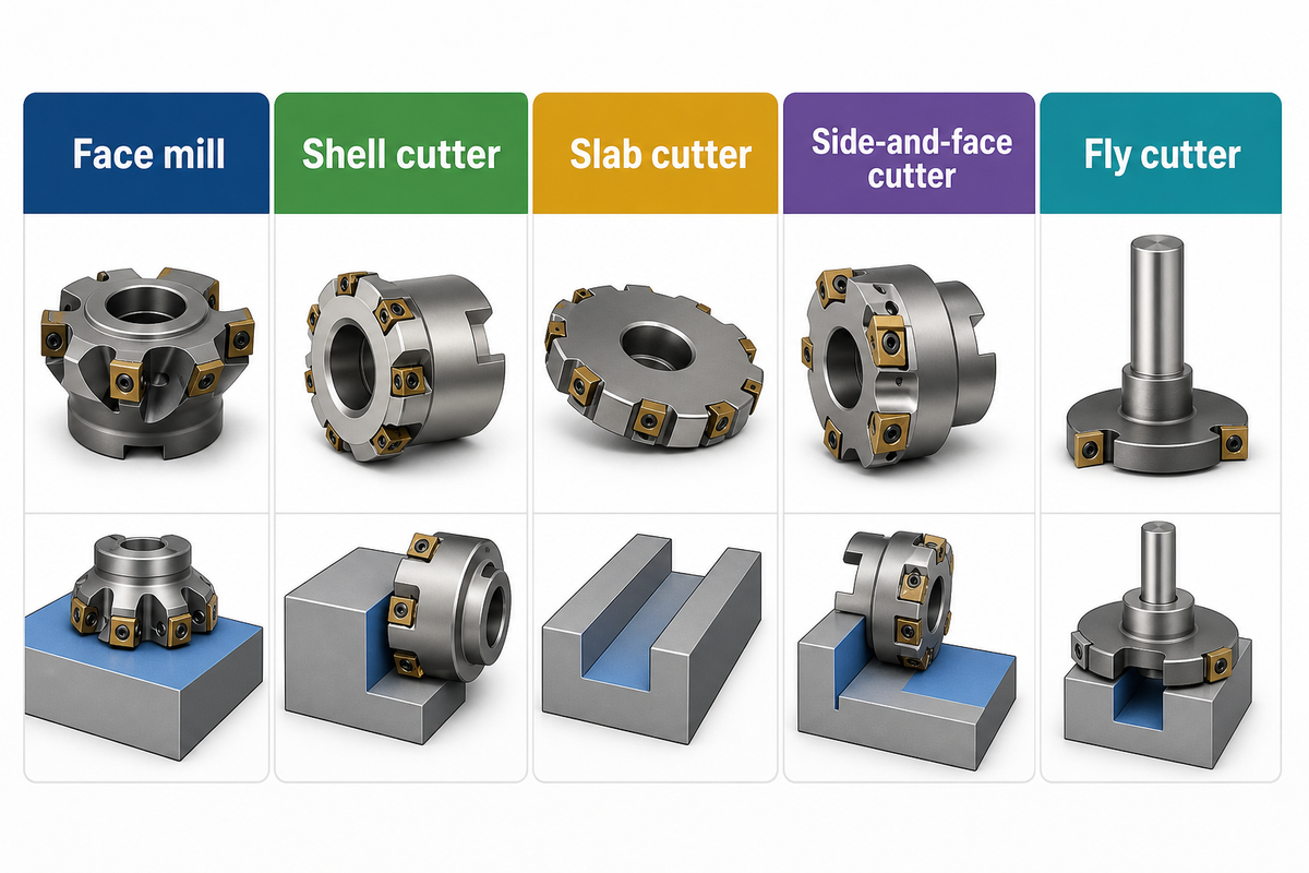
Broad-surface cutters primarily vary in tooth configuration, width, and type of installation. A face mill uses multiple cutting edges to mill a surface. For broad work, a shell or slab cutter is employed. Side and face cutters mill the slot walls and the periphery. A fly cutter makes a single point sweep.
The trade-off isn’t between old and new names. It’s a setup question. Determine spindle power and torque, arbor support, cutter-body clearance, tool entry and exit, insert setting, workholding, and whether the planned pass provides sufficient flatness and finish. Increasing the diameter can shorten tool travel, but it increases the moment on the spindle and fixture.
For quality release, record the assembled cutter runout or insert-height condition where it matters, not just the body model. Nominally identical face-mill inserts can load unevenly if one edge leads the others. That changes wear distribution and may impress a repeating pattern upon the surface.
Slot, Keyseat, Angle, Thread, and Gear Cutters
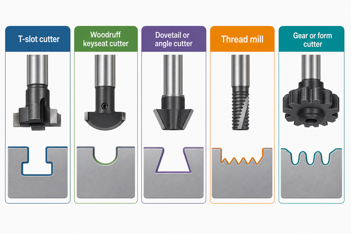
Dedicated profile cutters warrant use only when the edge must contact or replicate a geometry that a general end mill can’t produce. The profile isn’t the only consideration. Consideration also must be given to entry clearance, neck strength, bending load, chip removal, indexing, and the method of inspection to determine if the feature is controllable.
Let’s consider a T-slot. The head must pass through a smaller opening and cut a wider undercut. Neck diameter and reach influence the cutter’s stiffness. Dovetail cutters require a defined entry. Thread mills require a defined pitch and reliable helical interpolation. Gear and form cutters also require the correct profile and indexing system.
Do
- State the neck, undercut, angle, pitch, or form dimensions.
- Show the access path and adjacent obstructions.
- Name the gage or profile evidence required.
Don’t
- Order by family name without dimensional compatibility.
- Assume coolant reaches a hidden cutting zone.
- Leave tool wear out of profile acceptance.
Solid, Modular, or Indexable: Choose the Construction After the Family
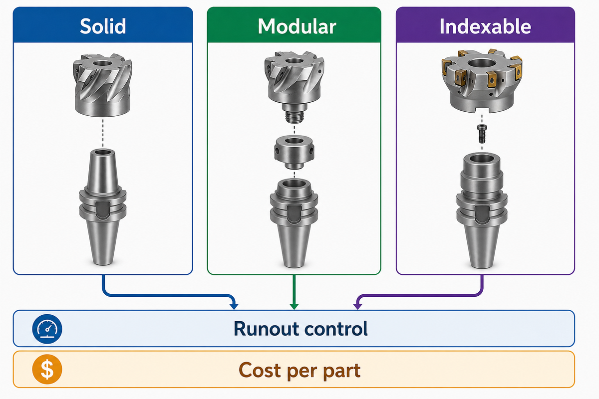
Construction is a three-way decision among a solid tool, an exchangeable-head or modular system, and an indexable body used for indexable milling. Consider usable diameter, reach, edge replacement, resetting, body reuse, runout control, inventory, and cost per part. The purchase cost alone won’t decide the construction option.
Indexable Milling and Machine Tool Constraints
| Construction | Typical strength | Watchpoint | Useful economic denominator |
|---|---|---|---|
| Solid | Compact geometry and continuous body | Resharpening, diameter loss, replacement stock | Qualified parts or volume removed per tool |
| Modular/exchangeable head | Reusable shank with replaceable cutting head | Connection stiffness, repeat length, compatible heads | Parts per head plus change and inventory time |
| Indexable | Replaceable edges and reusable body | Minimum diameter, insert seating, edge setting | Usable edges and predictable output per edge |
An example from one named industry states that a two-edge insert is priced at approximately $15 per edge, as compared to the cost of $3.75 for an eight-edge facing insert. This is an example of a worked application. It is not a universal break-even rule. If the eight-edge body isn’t able to fit and be stable in the required position to cut the surface, then the lower edge purchase cost doesn’t give this approach a lower cost for the part.
Cutter Material and Coating by Workpiece
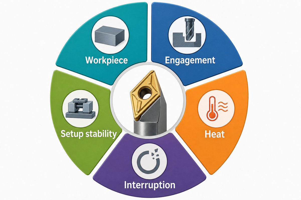
Choose the cutting material for the workpiece, engagement, heat, interruption, and setup stability rather than ranking materials by hardness alone. High-speed steel offers toughness; carbide supports greater hot hardness and rigidity but is less forgiving of impact and vibration. The cutting tool environment, including expected heat and wear, dictates coating selection.
Process engineers need to separate stable finishing from interrupted scale, rigid short-reach setups from slender extensions, and free chip evacuation from buried slots. The same nominal workpiece grade can behave differently after heat treatment or when the stock has a hard surface condition. Ask for the actual material specification and condition.
Zhenling’s company-provided material experience spans carbon and alloy steels, bearing steel, stainless steels including 303 through 321 grades, nickel-based and corrosion-resistant alloys such as C276 and 904L, and aluminum alloys. This first-party claim supports material-specific review; it does not justify inferring unverified cutter parameters without the drawing, material condition, tool system, and machine data.
Shanghai Zhenling Hardware Co., Ltd., founded in 2006, machines custom non-standard metal parts from customer drawings or samples. The company operates an 8,000-square-meter site with 6,000 square meters of workshop space and 3-axis, 4-axis, and imported 5-axis machining centers. These company-provided facts describe the available manufacturing context; they do not prove that a cutter, tolerance, or process is suitable without a drawing-specific review.
Hidden Bottleneck Map: Geometry Is Only One Constraint
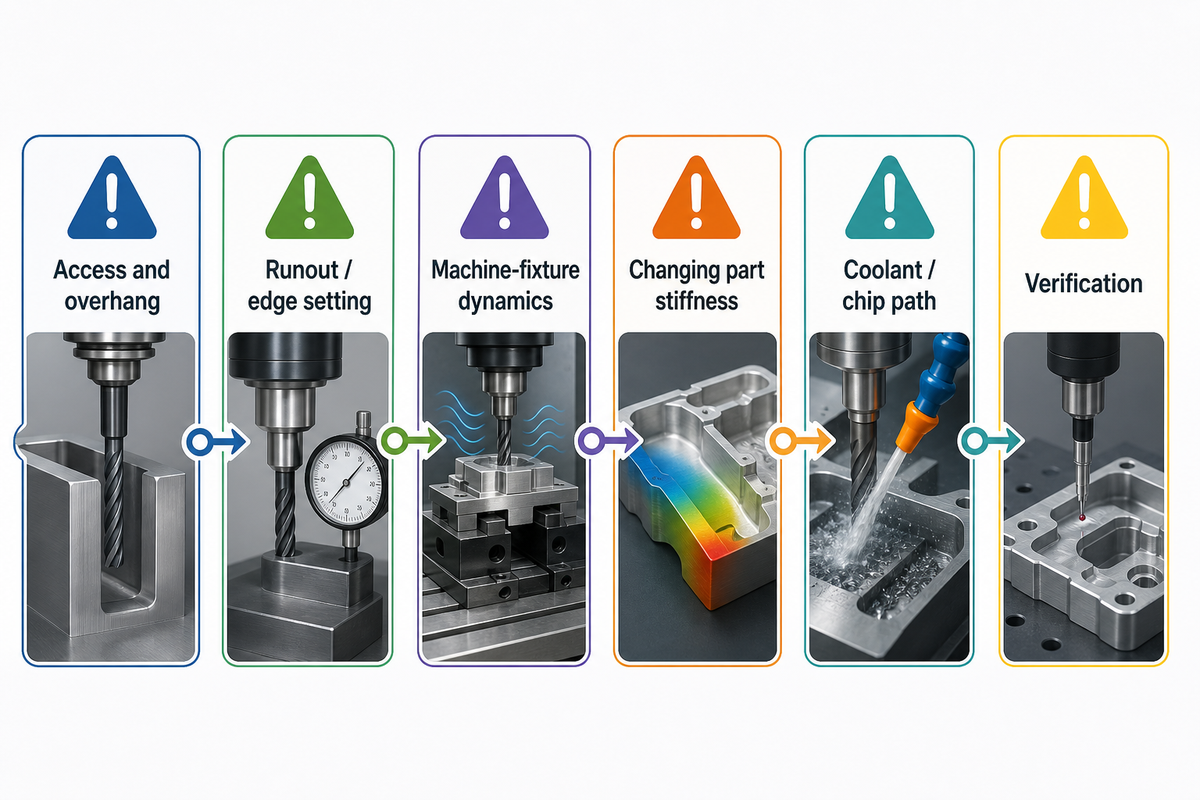
A feature-compatible cutter may still fail at one of the six hidden bottlenecks: access, assembled runout, structural dynamics, varying stiffness of the workpiece, chip and coolant path, and verification. Review these one by one because improving one may expose the next.
Chatter is a problem of the complete machine-tool-workpiece-workholding system. Slowing the spindle isn’t a universal cure; a different speed may fall into a more stable region. Similarly, tool length may be reduced but clearance is still required. Treat each remedy as a testable change and a recorded outcome.
Thin ribs and floors require a time-based view of rigidity. By the time of finishing, the stock that supported the first pass may be completely removed. Release plans must show roughing allowance, order of operations, support plan, and when the critical dimension or profile is measured.
The Four-Gate Cutter Shortlist
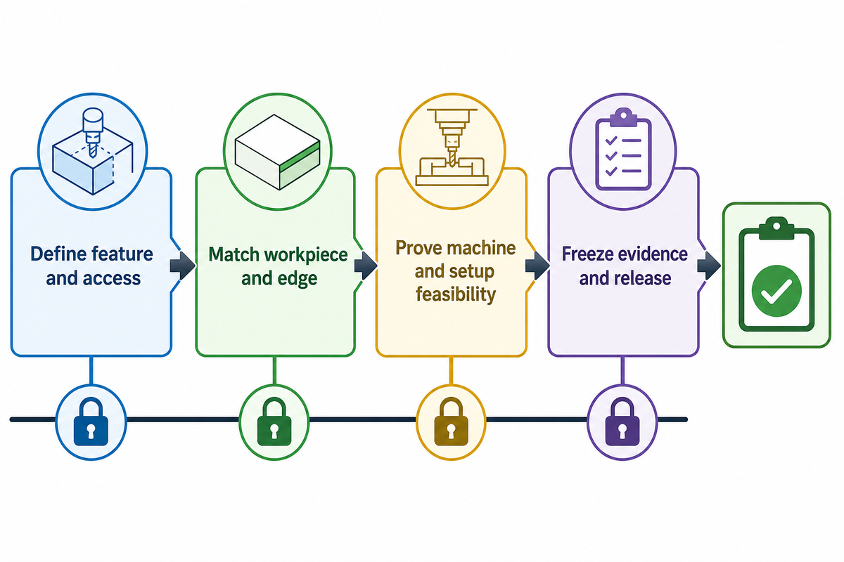
Production-ready shortlists should pass four gates: feature and access, workpiece and edge, machine and setup, then evidence and release. Each gate has a designated owner and artifact. That prevents a buyer from receiving three catalog numbers that cannot be compared on the same assumptions.
- Define feature and access – design provides geometry, corner or profile requirements, depth, adjacent walls, and collision boundaries.
- Match workpiece and edge – manufacturing records material specification and condition, engagement, interruption, finish, and chip-space needs.
- Prove machine and setup feasibility – process engineering checks interface, power, torque, reach, holder, workholding, coolant, chip exit, runout, and changing part stiffness.
- Freeze evidence and release – quality and procurement agree trial output, inspection method, tool-life/change rule, traceability, and change control.
Once the four gates use the same drawing revision and operating assumptions, you can compare commercial offers. Lower tool prices can hide additional setup costs, shorter predictable life, additional remeasurement, or additional finishing operations. Meanwhile, the most sophisticated body may add inventory and programming that a low-volume job couldn’t justify.
Cutter Selection Evidence Pack for a Machining RFQ
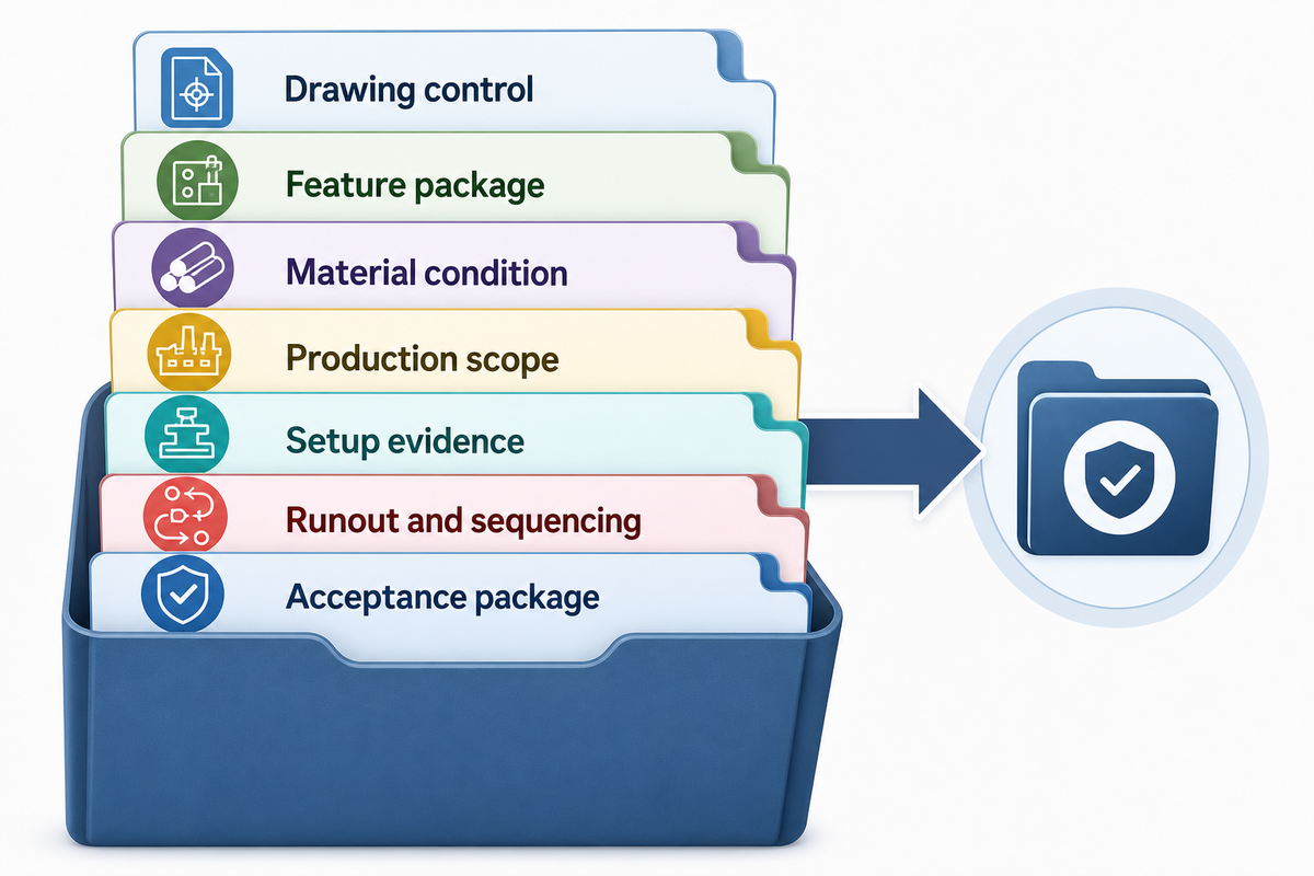
A useful machining request packages the drawing, material, quantity, machine assumptions, cutter constraints, and acceptance evidence in one controlled handoff. Zhenling crafts non-standard metal components based on customer-supplied drawings or samples. In those cases, lacking access, a condition, or inspection information becomes a technical concern rather than a potentially harmful gap.
The following fields can be copied to a machining request. They aren’t recommended value ranges since the appropriate value belongs to the drawing, the condition of the material, the machine, and the acceptance plan.
Cutter Selection Evidence Pack
| Parameter | Required value or range | Why it matters | How to verify |
|---|---|---|---|
| Drawing control | Revision, model, units, governing standard | Fixes geometry and interpretation | Approved document register |
| Feature package | Depth, width, radii, undercut, access envelope | Selects family and reach | Drawing and collision review |
| Material condition | Grade, heat treatment, hardness if specified, stock form | Changes edge and wear risk | Material certificate or agreed test |
| Production scope | Prototype/lot quantity, repeat schedule, allowed changes | Changes construction economics | Purchase order and change record |
| Setup evidence | Machine/interface, holder, overhang, workholding, coolant/chip route | Establishes feasibility | Setup sheet and trial record |
| Runout and sequencing | Measurement location plus thin-feature rough/finish order | Controls actual engagement and part movement | Indicator record and process sheet |
| Acceptance package | Critical dimensions, finish, sampling, report, tool-change rule | Defines a qualified part | First-article and lot records |
Before sending the inquiry pack, use the drawing review readiness checklist. This tool supports the separation of missing design authority from information that a manufacturing supplier can propose.
Need a cutter-aware review for a custom metal part?
Send the controlled drawing or sample details, material and condition, quantity, critical features, finish, and inspection deliverables. The technical team can identify access, setup, and evidence questions before quotation assumptions create production risk or avoidable shop-floor rework during production planning.
Frequently Asked Questions
What are the main types of milling cutters?
The main groups are end mills, face and peripheral cutters, and dedicated-profile cutters. End mills include square, ball-nose, corner-radius, roughing, tapered, and barrel profiles. Broad-surface tools include face, shell, slab, side-and-face, and fly cutters. Dedicated tools include T-slot, keyseat, dovetail, chamfer, thread, gear, and form cutters. Construction and substrate are separate choices.
How do I choose a milling cutter?
Screen the required feature and machine envelope together. Confirm access, material and condition, engagement, spindle and holder interface, power and torque, workholding rigidity, reach, coolant and chip path, runout, and inspection method. Then compare solid, modular, and indexable construction on qualified output and changeover burden rather than purchase price alone. For repeat work, also define the tool-change trigger, permitted process changes, evidence required after the holder, grade, coating, or supplier changes, and who approves deviation from the baseline.
What is the difference between an end mill and a face mill?
An end mill cuts with its end and peripheral edges, making it useful for pockets, shoulders, contours, and slots. Face mills use a wider body and multiple edges to sweep broad faces. The choice depends on feature access, diameter, power, rigidity, insert or edge setting, and the required flatness and finish. Both still need a verified setup and inspection plan.
Are more flutes always better?
No. More flutes can strengthen the core and add cutting edges, but they reduce chip-valley volume. Full slots and bulky chips may need more evacuation space. Engagement, diameter, coolant delivery, holder condition, and machine capability determine the practical selection.
Is an indexable cutter cheaper than a solid carbide cutter?
Not automatically. Indexable tools reuse the body and may offer several usable edges; solid tools can suit small diameters or compact access. Modular heads add another option. Compare qualified parts, predictable life, change time, inventory, regrinding, holder cost, and scrap risk.
References & Sources
- ISO 11529:2013 milling-cutter designation scope and 2024 lifecycle confirmation.
- ISO ICS 25.100.20 public catalogue of milling-tool standards.
- University of Wyoming Machine Shop Equipment and Best Practices cutter uses and conditional cutting guidance.
- University of Florida CNC Mill Resources flute-count and chip-evacuation guidance.
- International Journal of Machine Tools and Manufacture review milling chatter mechanisms and control context.
- University of Maryland cutter-set optimization paper tool loading and multi-part process-planning context.
- Modern Machine Shop, Find the Right Speed for Chatter-Free Milling system dynamics and stable-speed explanation.
Editorial boundary: cutter selection and cutting parameters remain application-specific. The released drawing, material condition, machine and holder system, workholding, approved process plan, and agreed inspection method control production. Company details are based on the manufacturer-provided brief unless otherwise linked.