

Programming reference · drawing-to-inspection handoff
CNC Coordinate Systems for Reliable Part Setup and Inspection
A CNC coordinate system maps programmed locations to the machine, workpiece, and tool. This visualization breaks up those elements, shows some examples of how to think about coordinates, and connects those examples to the drawing information a machining supplier would need.
- Drawing or sample review
- Material and quantity defined
- Datum and inspection inputs checked
- Quotation based on confirmed scope
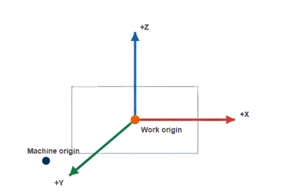
3 linear axes: X, Y, and Z describe signed linear directions.
·
3 rotary names: A, B, and C rotate about X, Y, and Z.
·
2 distance modes: G90 is absolute; G91 is incremental.
·
1 controlled handoff: Drawing, setup, program, and inspection must name their references.
·
3 linear axes: X, Y, and Z describe signed linear directions.
·
3 rotary names: A, B, and C rotate about X, Y, and Z.
·
2 distance modes: G90 is absolute; G91 is incremental.
·
1 controlled handoff: Drawing, setup, program, and inspection must name their references.
CNC Coordinates at a Glance
Machine zero and work zero are treated as interchangeable origins in many setup mistakes. That creates rework risk because a 2020 NIST advanced manufacturing report says coordinate-system definitions need careful handling during machine-model conversion, while the same X10 value can belong to 3 different frames in a machine shop. ISO 841:2001 supplies common coordinate and motion nomenclature; the active CNC machine and setup records still control the physical interpretation.
A useful four-part label
- Frame: machine, work, local, tool, drawing datum, or measurement.
- Origin: the zero point for that frame.
- Orientation: positive axis directions and active plane.
- State: active offset, units, distance mode, and compensation.
Machine frame
Its origin is established by the machine builder and homing system. Homing establishes the machine home position against a builder-defined reference point; a CNC program may then reference machine coordinates. Syntax and safe use belong to the controller manual.
Work frame
The work coordinate system (WCS) connects the part origin point to the CNC machine. G54 through the available work-offset registers let a program reuse part coordinates at an established fixture location.
Tool frame
Tool length and radius data relate the cutting edge to the controlled axis position. A tool change requires the correct tool record but does not replace the work offset or drawing datum.
CNC Axis Directions and Rotary Axes
A Cartesian coordinate system defines position through three axes, and the declared machine axes express those directions as X, Y, and Z. An axis letter describes a coordinate direction, not necessarily the moving body; machine construction determines which component moves. ISO 841 separates that convention from physical motion because a 3-axis CNC machine, trunnion, swivel-head, or turn-mill can realize the axes in different ways.
X axis 01
One linear direction in the Cartesian frame. On a common vertical mill diagram it is often shown left to right across the machine table.
Y axis 02
The second linear direction, perpendicular to X. The right-hand relationship fixes its sign within the declared frame.
Z axis 03
The axis aligned with a primary spindle in this machine diagram. Machine construction decides which body actually moves.
A rotation 04
Angular motion about the X axis. Do not infer table-versus-head motion from the letter alone.
B rotation 05
Angular motion about the Y axis. Pivot location and kinematic transformation remain machine specific.
C rotation 06
Angular motion about the Z axis. Turning spindles and rotary tables need controller and builder context.
SYSTEM ARCHITECTURE
Machine, Work, Tool and Datum Frames
Production handoffs cross several frames. Treating them as one origin is a common route to an apparently correct program that does not match the drawing or inspection report. ISO 841:2001 provides the machine-motion nomenclature, while ISO 5459:2024 distinguishes drawing datum specification from verification operations for the programmer, setup team, and inspector.
Frame
What it locates
Where the decision belongs
Boundary to confirm
Machine coordinate system
Axis position relative to machine zero
Machine and controller records
Homing and builder-defined directions
Work coordinate system
Programmed part locations relative to work zero
Setup sheet and offset register
Fixture alignment and active register
Tool compensation frame
Cutting edge relative to the controlled tool position
Tool list and controller table
Length, radius, sign, and active compensation
Drawing datum system
Geometric specification references
Controlled drawing revision
Primary, secondary, and tertiary datum intent
Measurement frame
Reported feature locations during verification
Inspection plan and report
Alignment to the specified datum system
Need a frame decision, not another definition?
Use the router to identify the primary coordinate frame and the record that should carry it.
G53 and G54 Through G59.3 Coordinate Reference
If the setup record fails to name the active work offset, it will be lost during fixture changes. This introduces either a collision or a rework risk because G53 and at least 6 standard G54-family selections address different reference questions; ISO 841 does not specify controller-related storage behavior.
G53: machine-coordinate move
Use it only with the syntax, modal rules, compensation state, and clearance procedure approved for the specific control. It is not a substitute for checking where the machine can safely move.
G54 family: work-coordinate selection
The selected register shifts programmed part coordinates to an established work origin. Available extended registers and storage rules differ among controls.
Offset stacking needs a record
- Identify the active work offset in the setup sheet.
- Check local or global shifts such as G52/G92 only against the controller manual.
- Record which fixture, part, and revision each stored value serves.
COORDINATE LAYERS
Work Offsets and Distance Modes by Example
The numbers in this table bring out the coordinate layers; they do not represent a complete command language. Controller-related selection, persistence, and safety remain outside this browser example. See the Tormach G90/G91 reference for one documented controller implementation.
Compare absolute and incremental endpoints
The calculator shows the arithmetic side by side. It never sends code to a machine.
Open the G90/G91 Calculator
Current point: X10 Y20 Z5
G90 with X5 Y-5 Z0 → X5 Y-5 Z0
G91 with X5 Y-5 Z0 → X15 Y15 Z5
G90 with X5 Y-5 Z0 → X5 Y-5 Z0
G91 with X5 Y-5 Z0 → X15 Y15 Z5

| Code or example | Reference used | Plain-language result | Confirmation needed |
|---|---|---|---|
| G53 X0 Y0 Z0 | Machine frame | Addresses machine-coordinate zero values | Controller syntax, compensation, and safe path |
| G54 | Work offset 1 | Selects the first standard work frame on many controls | Actual register mapping for the control |
| G55 | Work offset 2 | Selects another stored work frame | Fixture-to-register assignment |
| G56 | Work offset 3 | Supports a separate origin or fixture | Setup-sheet identity |
| G57 | Work offset 4 | Keeps part coordinates reusable at another location | Recorded origin and revision |
| G58 | Work offset 5 | Adds another declared work frame | Available register and stored values |
| G59 | Work offset 6 | Selects the sixth standard work frame on many controls | Control-specific availability |
| G59.1–G59.3 | Extended work offsets | May expose 3 additional work frames | Controller support and numbering |
| G90 X25 Y10 Z-2 | Active coordinate frame | Endpoint is X25, Y10, Z-2 | Active frame, units, plane, and compensation |
| G91 X25 Y10 Z-2 | Current point | Adds +25, +10, and -2 to the current coordinates | Current position and modal state |
COMMERCIAL INTEGRATION
Drawing Review, Quotation and Production Handoff
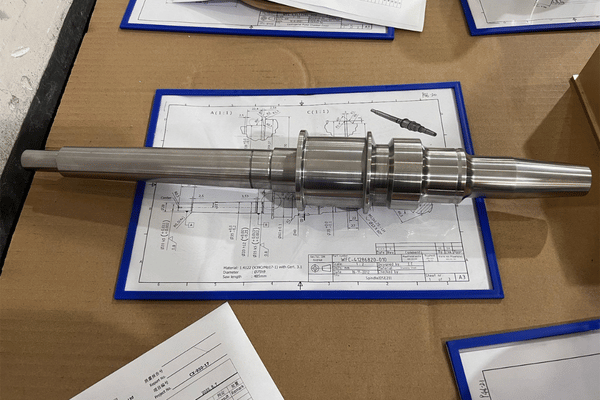
Coordinate systems become commercially significant when they are provided with controlled drawings, part definitions, and acceptance criteria. We specify the missing manufacturing and inspection inputs together with the drawing or sample prior to providing a quotation.
01
Files
Send the controlled drawing and any available 3D model or physical sample. Identify datums, tolerances, notes, and revision status.
02
Order scope
Quantity, material, finish, and required records let the quotation reflect the actual scope.
03
Commercial terms
Delivery, documentation, payment, and trade terms are confirmed for the specific quotation.
Include these coordinate-critical inputs
- Drawing number, revision, units, and 3D model relationship.
- Datum reference frame and critical geometric tolerances.
- Features that share a setup or must be related across setups.
- Inspection report, sampling, and traceability requirements.
- Material grade, finish, quantity, and target schedule.
SYSTEM ACCURACY
Nominal Coordinates and Achieved Position
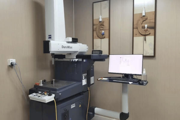
Programmed coordinates indicate nominal targets. Actual physical position also depends on the machine model, coordinate conversions, geometry, alignment, thermal state, loading, tool behavior, and the method of measurement.
1. Commanded
The program expresses a coordinate in an active frame. Modal state and compensation affect how the control interprets it.
2. Achieved
The tool and workpiece reach a physical relationship. A coordinate value alone does not quantify the remaining error.
3. Measured and accepted
Inspection aligns measurements to a defined datum system and applies the drawing requirement. This is a separate conformance decision.
No universal accuracy promise follows from the diagram
The NIST AMS 100-36 report identifies uncertainty sources in machine tools, processes, environments, models, and coordinate conversions. Project tolerances need drawing-specific process and inspection review, not a generic coordinate chart.
SYSTEM ARCHITECTURE
The Coordinate-Boundary Atlas
The Atlas separates coordinate control into 6 decisions linked together instead of treating the control system as a unified, connected chain. Datum, work offset, program, and measurement frames cannot be treated as interchangeable because silent translation creates mismatch and conformance risk.
1
Drawing datum
Use the controlled drawing to establish specification references, units, tolerances, and revision.
2
Workpiece alignment
Relate a real surface or feature to the planned work origin and fixture during setup.
3
Controller offset
Store the machine-to-work relationship for that setup in a declared register.
4
Commanded motion
Interpret program coordinates through the active frame, units, plane, distance mode, and compensation.
5
Measurement frame
Align observed feature data with the stated datum system and reporting method.
6
Conformance decision
Evaluate the measured result against the controlled drawing requirements and the agreed acceptance plan.
Parts We Machine and Coordinate-Controlled Work at Zhenling
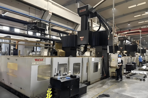
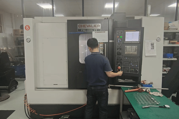
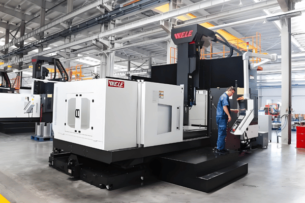
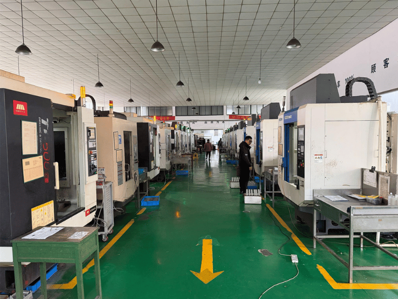
Shanghai Zhenling Hardware Co., Ltd. has manufactured non-standard metal components since 2006 at its factory in Jiashan County, Zhejiang, China, which includes an 8,000-square-meter factory and 6,000-square-meter workshop. We customize parts from client drawings or samples using CNC turning, milling, grinding, boring, radial drilling, and wire-cut EDM on 3-axis, 4-axis, and imported 5-axis machining centers.
A manufacturing bridge, not a glossary
Unlike a standalone coordinate tutorial, this page carries the frame decision into drawing and inspection inputs. The differentiator is the documented handoff: confirm against the controlled drawing before machining scope is quoted.
Non-standard component work
We machine assemblies, flanges, rollers, bent-pipe components, valve bodies, and plugs, plus other drawing-based machine parts.
Material experience
Our stated processing range includes carbon, alloy, and bearing steels; 303, 304, 304L, 316, 316L, and 321 stainless steels; and nickel-based alloys, C276, 904L, and aluminum alloys.
Review starts with the drawing
Part geometry, datum intent, material, hardness, tolerances, quantity, and inspection requirements determine the process review.
Capability is project specific
Machine availability alone does not establish a part tolerance or inspection method. We confirm those items against the submitted drawing and quotation scope.
OPERATIONAL LIMITS
Coordinate-System Limits and Safety Boundaries
This page is about concepts and review inputs, not an operating procedure. A browser diagram or calculator must never be treated as authority for an unverified machine move.
Controller behavior varies
Offset registers, persistence, extended codes, reset behavior, and compensation interactions can differ. Use the manual for the exact controller version. The LinuxCNC coordinate-systems reference illustrates one controller-specific implementation.
Machine kinematics vary
The axis letter does not reveal whether a table, head, slide, tool, or workpiece moves. Confirm the builder’s diagram and pivot definitions.
Simulation is not final proof
Simulation is not a substitute for physical setup, tool data, clearance, and approved prove-out controls. It can still help expose program errors.
Program coordinates are not inspection results
Conformance requires the stated datum alignment, measurement method, and acceptance rule. Keep that record separate from the offset table.
Pre-run confirmation
- Machine homed under the approved procedure.
- Correct program and revision loaded.
- Units, plane, distance mode, and work offset confirmed.
- Tool and compensation data checked.
- Clearance and first-run controls applied by qualified personnel.
SYSTEM RESOURCES
Send Your Drawing for Coordinate and Datum Review
Provide details on the revision, model, material, quantity, critical features, and inspection requirements. We will note the input gaps, scope machining, and draft the quote based on the confirmed details.
Open the Drawing Review Form
The delivery, documentation, payment, and trade terms are confirmed for this quote.
TECHNICAL REFERENCE
CNC Coordinate System FAQ
Machine zero anchors the machine coordinate frame established through the machine’s design and homing system. Work zero is the selected origin for part programming, connected to the machine by a recorded work offset.
No. G54 names a work-offset selection on many controls, while the stored values establish its physical relationship for the current setup. Verify the register and fixture assignment.
G53 addresses the machine coordinate system on controls that implement it, while G54 activates a stored work coordinate system. Their exact syntax and modal interactions require the controller manual.
G90 uses absolute target coordinates in the active frame. G91 treats programmed axis values as signed increments from the current point.
Lathe coordinate system diagrams reflect different structures and primary motions from mills. ISO 841 supplies a common programming abstraction, but the machine-builder diagram remains necessary for the actual kinematics.
No. They name rotations about X, Y, and Z, but a machine may realize them through a rotary table, trunnion, swivel head, spindle, or combined kinematic system.
No. A drawing datum belongs to the geometric specification, while a work offset connects the setup’s work frame to the machine. An approved translation may relate them, but neither should silently replace the other.
Not as a universal rule. The answer depends on the measurement objective, uncertainty, datum alignment, process controls, customer requirement, and accepted inspection plan.
Provide the controlled drawing revision, units, datum scheme, critical tolerances, 3D model relationship, material, finish, quantity, and required inspection records. Identify features that must remain related across setups.
Review timing depends on drawing completeness, material, process scope, quantity, and inspection requirements. A complete drawing package helps the engineering review start without a round of missing-input questions.
Provide the controlled drawing and any available 3D model or physical sample. Identify the datums, geometric tolerances, surface requirements, and inspection notes that govern acceptance.



