CNC Fundamentals: A Practical Guide to CNC Machining

CNC fundamentals are the core principles that connect a drawing, machine, toolpath, and inspection record to a repeatable, inspected part. This guide discusses the decisions made by engineers and buyers before the production of a custom component, covering CAD/CAM, machine tool, tooling, workholding, materials, tolerances, and procurement.
Review the CNC fundamentals process with Zhenling
What are CNC fundamentals?
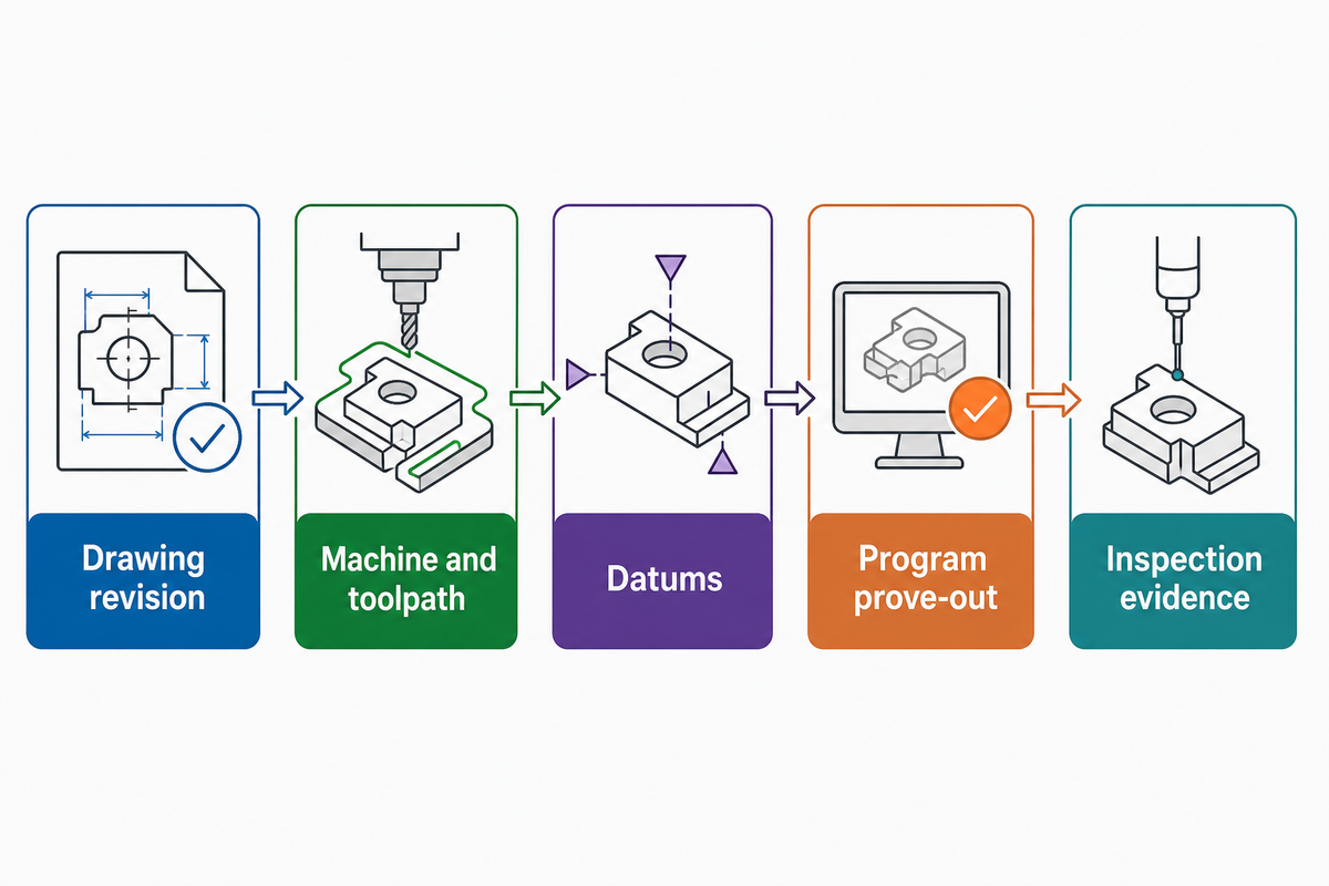
CNC fundamentals establish the controlled chain from drawing to output. Computer numerical control converts programmed coordinate moves into machine motion, while the operator, programmer, engineer, and buyer each control a different risk. The process checks the drawing revision, chooses a workable machine and toolpath, establishes datums, proves the program, cuts the material, and records inspection evidence.
For readers comparing fundamentals of CNC machining with fundamentals of CNC programming, start by identifying the axes, control, path, and feedback before copying code. That same traceability test is the practical core of CNC part programming fundamentals.
The input is a current drawing or sample, material and quantity. The process is CAD/CAM, program, set up, machine, and verify. The output is a part whose critical features can be traced to a revision and an acceptance rule. NIST indicates that the G-code issued in conjunction with traditional CNC/CAM control and measurement is mostly commands without feedback. Connected CNC/CAM control and measurement can improve manufacturing feedback, but the architecture and interface determine what the system can observe and control (NIST review). These fundamentals are applicable across the machine tools used in job shops.
Is CNC difficult to learn?
Learning CNC is a series of connected skills. An operator learns safe setup and offsets; a programmer learns CAM and how to prove a part out; an engineer learns how to design and apply tolerancing; a buyer learns how to specify a process and inspection. Purdue’s course introduces the concepts of linear and rotational movements, control systems, and path systems, as well as feedback in isolation (Purdue WHIN).
Drawing-to-Part Control Chain
Revision → feature and datum review → machine and setup choice → CAM and program proof → controlled cutting → in-process checks → final inspection record.
Revision → feature and datum review → machine and setup choice → CAM and program proof → controlled cutting → in-process checks → final inspection record.
How the CNC machining process works: CAD to inspected part
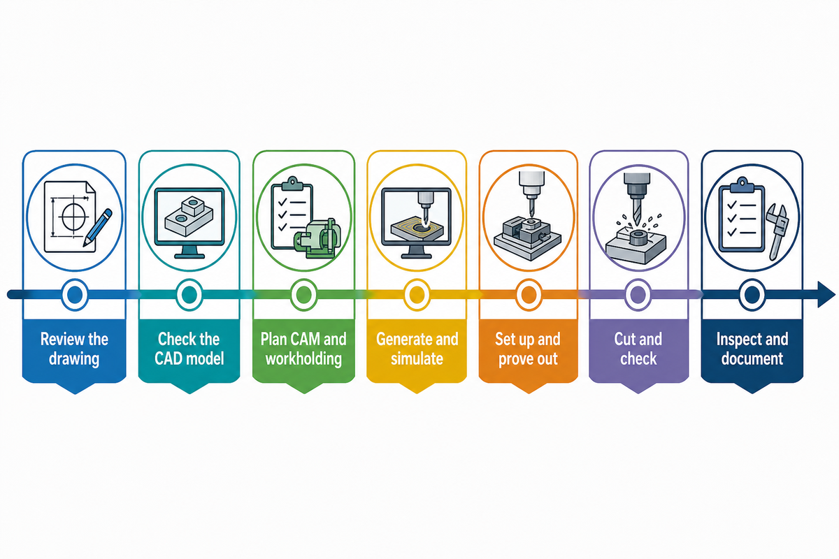
A production-ready CNC machining process separates seven controls so a mistake is found before it becomes a batch problem. See the process overview and coordinate-system guide for related RFQ checks. The steps below modify the practical nine-step process documented by CNCCookbook and provide the inspection and sourcing evidence that industrial buyers require (in CNCCookbook roadmap).
- Review the drawing. Confirm revision, units, material condition, surface finish, critical-to-quality features, and datum scheme.
- Build or check the CAD model. Resolve missing radii, deep pockets, thin walls, threads, and access before programming.
- Plan CAM and workholding. Select stock, datums, setups, cutters, and a sequence that leaves inspection access.
- Generate and simulate the toolpath. The post-processor must match the controller; simulation checks collisions and excess stock.
- Set up and prove out. Load tools, establish work and tool offsets, verify clamping, then run a controlled first piece.
- Cut and check. Watch chips, load, tool wear, temperature, and dimensions that can drift during the run.
- Inspect and document. Report critical dimensions, method, instrument status, sampling, nonconformance disposition, and the drawing revision.
How can I learn CNC machining for beginners?
Start with coordinate systems and machine safety, then learn one simple CAD/CAM workflow, read a setup sheet, simulate a toolpath, and measure a practice part. Following a structured sequence is safer than copying an unknown G-code file. For a custom part, the first learning task is often reading the drawing and identifying what must be proven.
| First-pass RFQ decision item | What to state | Why it changes a quote |
|---|---|---|
| Revision and units | Revision, inch or mm, and datum scheme | Prevents work to an obsolete model or mixed inch/mm data. |
| Material and condition | Grade, heat treatment, and stock condition | Changes tooling, heat treatment, stock, and cycle assumptions. |
| Quantity and repeat order | Prototype count and repeat quantity | Changes setup amortization and inspection sampling. |
| Critical features and finish | Tolerances, surface finish, and threads | Determines secondary operations and evidence required. |
| Stock envelope | Blank length, width, height in mm or inch | Sets machine envelope, workholding, and material waste. |
| Tolerance example | 0.13 mm, 0.051 mm, or a drawing value | Signals whether standard or precision routing is required. |
| Hole requirement | Diameter, depth, and reamed value such as 0.0127 mm | Can add drilling, boring, reaming, or inspection steps. |
| Inspection evidence | Gauge resolution, CMM need, and reference temperature | Changes measurement time and report content. |
| Delivery assumptions | Lead time in days, packaging, and shipping term | Prevents an attractive unit price from hiding schedule or logistics work. |
CNC machine types and what each axis adds
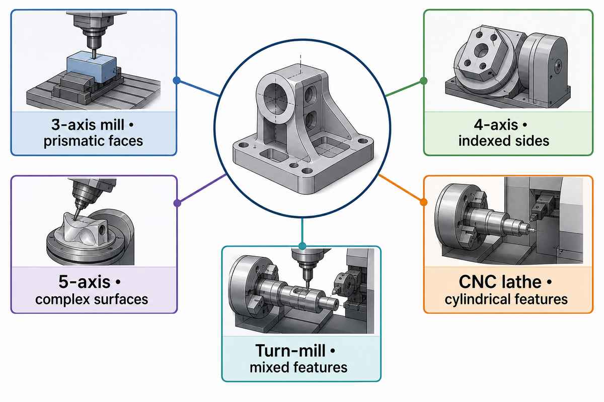
When selecting a CNC machine, consider access to features, shape of the workpiece, and rigidity rather than the number of axes. The design of the workpiece, as well as the number of setups, should also be considered. In machining, a CNC milling machine holds the workpiece and a rotating cutter removes material. Turning centers rotate the workpiece to machine shafts, bores, and threads. A CNC lathe is the typical first choice to machine this geometry. A machining center has automatic tool changes and can have a rotary axis. Grinders and wire EDM are finishing or special geometry processes where cutting tools are not the preferred method.
Five-axis machine access can reduce reclamping, but it does not guarantee better accuracy. Peer-reviewed literature reports that one tested system had a maximum trajectory error of 19 micrometers before compensation and 1.5 micrometers after compensation; kinematics, interpolation, calibration, and compensation all affect the final accuracy of that machine (five axis error study). Treat these numbers cautiously, as they are specific to that study.
| Machine type | Part or feature class | Access question | Likely route |
|---|---|---|---|
| 3-axis mill | Prismatic faces and holes | Can one setup reach the datum faces? | 3-axis mill or machining center |
| 4-axis setup | Indexed sides or angled features | Will a rotary axis reduce reclamping? | 4-axis setup or indexed fixture |
| 5-axis center | Complex continuous surfaces | Is simultaneous access worth programming and verification? | 5-axis machining center |
| CNC lathe | Cylindrical outside or inside features | Does the part need to rotate? | Lathe or turn-mill |
| Turn-mill | Mixed radial and milled features | Can it reduce a second setup? | Mill-turn route |
| Grinding machine | Fine finish or hardened geometry | Is cutting force or finish the constraint? | CNC grinding |
| Wire EDM | Thin slots or special profiles | Would a wire process reach the profile? | Wire EDM |
| Machining center | Multiple tools and repeat batches | Will automatic tool change reduce handling? | 3-, 4-, or 5-axis center |
| Manual-support cell | Prototype or teaching work | Can the operator verify each offset safely? | Supervised CNC cell |
What is a good beginner CNC?
The right beginner CNC is the smallest safe system that can make the intended feature family. For a learner making flat plates may need a simple mill; a shaft maker needs a lathe; a buyer of pressure-vessel or fluid-control parts needs a supplier able to prove material, datums, tolerances, and inspection.
CNC programming, coordinates, G-code, and CAM
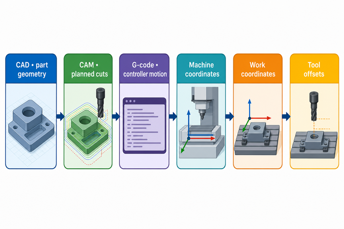
In the CNC software stack, CAD describes the part, CAM plans the cuts, and G-code communicates motion to the controller. CAM software converts the model into a path that the controller interprets and runs. Machine coordinates describe the machine’s reference; work coordinates describe the part datum. Tool length and radius offset transform the virtual tool path to the physical tool. From the tool path, check the cutter, material, chip load, tool rigidity, and spindle speed.
A post-processor is not a universal translator; controller family, agency, units, work offset convention, canned cycles, and probing options affect the outcome. NIST says that G-code has limited resolution for feedback. Separate, more sophisticated, standards can identify the state of the machine. In this case, a programmer must verify the outcome on the target control unit (NIST CAM/CNC research).
(concept only — verify with the machine manual)
G90 G54        (absolute mode; selected work offset)
S1200 M03      (spindle command is example data)
G00 X0 Y0      (rapid to a verified clearance position)
G01 Z-1.0 F80   (feed move; prove depth and feed before cutting)
M05            (stop spindle)
This is a teaching sketch, not a production program. Simulation, a dry run, single-block execution, and a controlled first piece protect the machine and part.
Illustrative CNC inspection worksheet
The values below are placeholders for explaining a setup record, not machining limits or a quotation. Replace every value with the current drawing, machine manual, material data, and agreed inspection plan.
| Field | Illustrative entry | Control question |
|---|---|---|
| Stock envelope | 120 mm × 80 mm × 25 mm | Does the fixture leave tool clearance? |
| Critical hole | 10 mm diameter × 18 mm depth | Which tool and gauge verify it? |
| Dimensional tolerance | ±0.05 mm | Is that tolerance functional and measurable? |
| Finish example | 1.6 µm Ra | Does the route need a finish pass or grinding? |
| Reference condition | 20°C | What temperature does the acceptance rule specify? |
| Spindle example | 6,000 rpm at 5 kW | Has the cutter, material, and machine been checked? |
| Feed example | 450 mm/min with 35 mm stick-out | Is chip load compatible with rigidity? |
| Inspection sample | 3 parts, 100% critical-feature check | Who signs the first-piece decision? |
| Run and delivery | 2 hours machining, 7 days lead time | Are cycle and logistics assumptions explicit? |
| Clamping example | 250 PSI fixture pressure | Will clamping hold without distorting a thin wall? |
Cutting tools, spindle, feed rate, and chip control
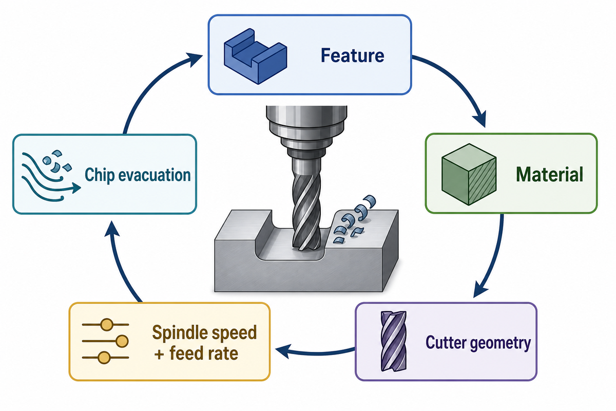
Select a cutter based on features and materials. End mills, drills, boring tools, and inserts for turning and facing are the main classes of CNC tooling. Flute count, helix, coating, stick-out, coolant, and chip space affect heat and chip evacuation from the cutter. The Haas course on speed and feeds shows that the spindle speed and feed rate are related in that one cannot be selected without the other. They are paired variables. (Haas calculation guide).
| Feature | Starting cutter family | First check |
|---|---|---|
| Open pocket | End mill with chip space | Chip evacuation and tool deflection |
| Thin wall | Small radial engagement and sharp geometry | Workholding force and wall movement |
| Deep hole | Drill or peck strategy | Chip packing, coolant, and tool length |
If a finish turns rough, check tool runout, stick-out, rigidity, chip load, and vibration before simply increasing speed. If a tool breaks, check chip packing, workholding, and the programmed numbers. Chip packing, workholding, and programmed numbers are just part of the control. Flute count, radial engagement, depth of cut, coolant, toolholding, and the entry or exit strategy can also influence chip thickness and tool wear. Cadrex’s guide also connects tooling selection to material, machine, speed, and precision (Cadrex starter guide). For feature-level comparisons, use Zhenling’s milling cutter guide.
Workholding, datums, and setup repeatability
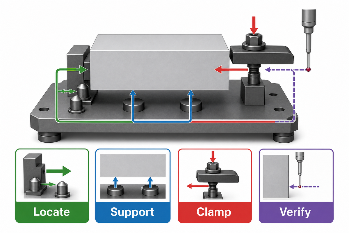
Repeatability begins with four separate controls: locate, support, clamp, verify. Each clamping system locates the part against a datum, while supports take the cutting loads. Clamping systems must hold the part without distorting the part’s geometry. Verify all critical geometry by checking the offset and first piece. Even with an unchanged program, reclamping can change the thin wall or shift the datum.
What should a CNC setup sheet contain?
Record part revision, stock size, machine, fixture ID, datum scheme, tool list, offsets, probing method, torque or clamp notes, clearance checks, first-piece dimensions, and sign-off. A practitioner discussion of drill-length variation shows why setup discipline and inspection should be combined before production (discussion).
Locate → Support → Clamp → Verify
Ask where the datum is established, where the cutting force travels, what prevents distortion, and what measurement proves the setup before the run.
Ask where the datum is established, where the cutting force travels, what prevents distortion, and what measurement proves the setup before the run.
Materials, tolerances, GD&T, and inspection
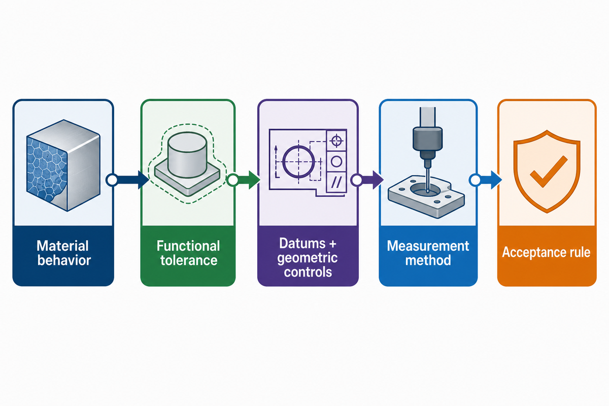
Material, tolerance, and inspection belong together in an engineering design decision. Carbon and alloy steels, stainless steels, nickel alloys, and aluminum alloys respond differently to heat, cutting force, corrosion, and tool wear.
Brand-provided capability note. Shanghai Zhenling Hardware Co., Ltd. says it has operated since 2006 and makes custom non-standard metal parts from drawings or samples. Its supplied material list includes carbon and alloy steels, stainless steels, nickel alloy C276, 904L, and aluminum alloys; treat these as company-provided capabilities to confirm against the drawing and service conditions. The company profile also lists CE and ASME export certifications and overseas markets; these remain brand-provided until independently verified.
GD&T communicates functional intent through datums and geometric controls. ASME’s public certification page says the current program reflects ASME Y14.5-2018 and names datum features, material condition modifiers, form, orientation, and location controls as core knowledge (ASME GDTP page). Quality control binds the drawing and inspection together. Acceptance requires an acceptance decision only when the reference temperature, calibrated instrument, sampling plan, uncertainty, and decision rule are agreed; a micrometer may be suitable for one feature while a CMM is better for another.
How tight should CNC machining tolerances be?
Use the functional requirement, not a “tight” default. A 0.13 mm example is provider-specific; check function and process capability. Protolabs lists 0.13 mm standard, 0.051 mm precision, and 0.0127 mm reamed-hole examples; unnecessary tightness can add grinding, EDM, cost, and lead time (Protolabs tolerance guide). An attributed aerospace case reports ±0.0005 inch on an aluminum housing with Zeiss CMM checks; it is not universal (BTX case study).
| Inspection-Evidence Checklist | Record |
|---|---|
| Drawing control | Revision, units, governing GD&T edition, datum reference frame |
| Measurement method | Instrument, calibration status, resolution, temperature |
| Sampling and decision | First piece, in-process, final sample, acceptance rule and disposition |
How to specify a CNC part and compare supplier quotes
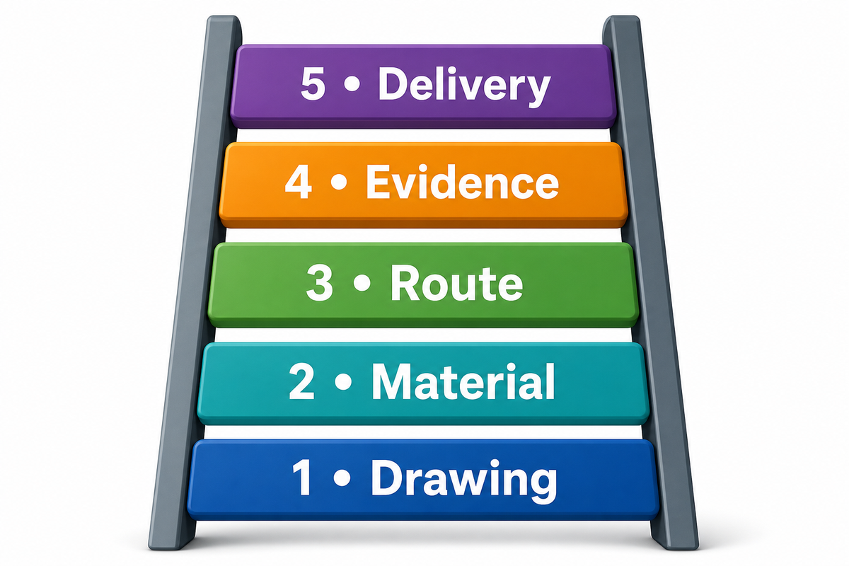
Comparable quotes can be requested when the same assumptions for revision, material, process route, inspection, and delivery are made. See ASME GD&T guidance for the datum and tolerance context behind comparable specifications. Ask every supplier to state what is included: programming and setup, raw stock, heat treatment, deburring, surface finish, inspection report, packaging, Incoterms, and lead time.
| Quote Comparability Ladder | Buyer question |
|---|---|
| 1. Drawing | Are revision, units, datums, and critical features identical? |
| 2. Material | Is grade, condition, certification, and traceability included? |
| 3. Route | How many setups, secondary operations, and finishing steps are assumed? |
| 4. Evidence | Which dimensions, reports, and samples will be delivered? |
| 5. Delivery | Are lead time, packaging, shipping term, and approval loop stated? |
Please send a drawing or sample with quantity, material, critical dimensions, finish and inspection requirement, and destination. Zhenling’s technical team can review the drawing to part conversion and determine any assumptions that are missing before a formal quotation is made.
Where CNC machining is heading: 5-axis, automation, and connected inspection
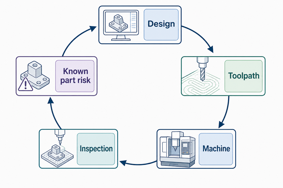
The useful CNC trend is a tighter feedback loop between design, toolpath, machine, and inspection. NIST’s CAM/CNC review outlines the limitations associated with command-only G-code. One peer-reviewed Machines paper presents a tool-health digital-twin architecture for predictive maintenance, while a 2026 ManufacturingTomorrow article by Dominique Galmel of DELMIA discusses AI-assisted feeds and speeds, digital twins, connected machine data, and hybrid manufacturing (ManufacturingTomorrow trend article).
An automatic toolpath selection system that incorporates real-time error correction and real-time feedback is described in the patent abstract (CN103076757A). Consider it evidence for future technology. For a buyer, the practical question is whether a pallet changer, tool monitor, 5-axis setup, or digital twin reduces a known setup, access, or inspection risk on the part in front of you.
The next step is to map out one real-life drawing. Then, determine the feature with the highest risk, describe the 3-axis and 5-axis milling strategies, indicate the datum and inspection constraints, and request quote(s) including the described assumptions. This exercise converts fundamentals of CNC into a decision that you can evaluate.
Frequently asked CNC fundamentals questions
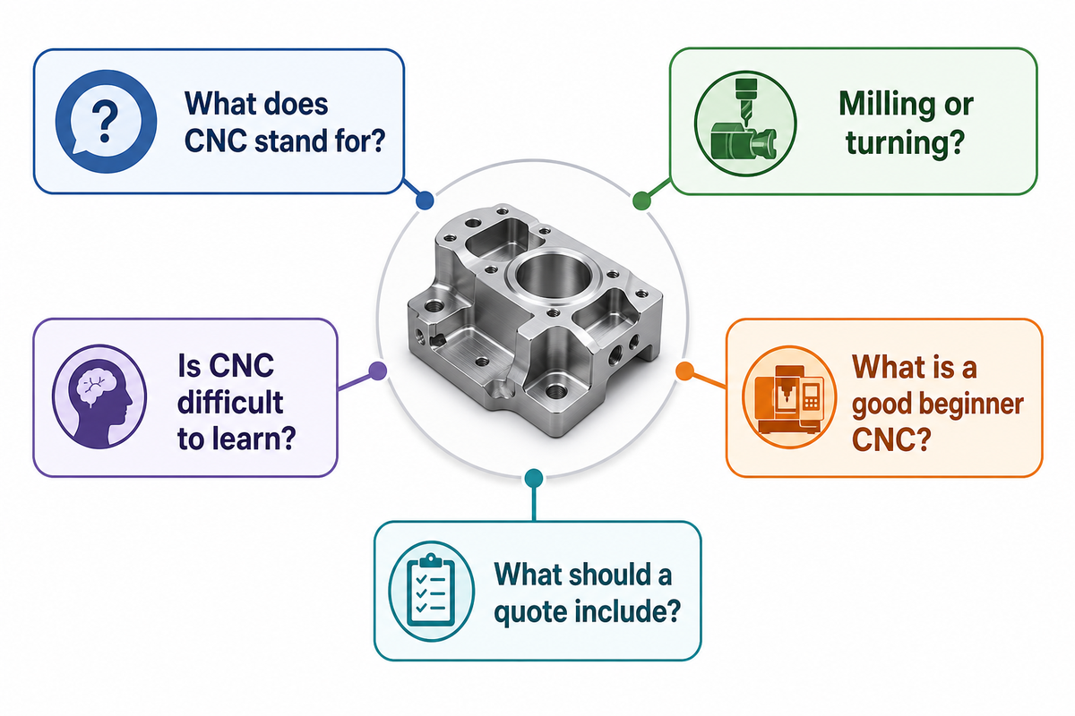
What does CNC stand for?
CNC means computer numerical control: NIST definition instructions command axes, spindle, and auxiliary functions. It depends on drawing, setup, workholding, tool offsets, prove-out, and inspection. CNC names a control method; it does not specify machine type, tolerance, material, or evidence.
What is the difference between CNC milling and CNC turning?
A milling machine holds the workpiece while a rotating cutter removes material. Turning rotates the workpiece against a fixed tool for diameters, faces, grooves, and threads. Mill-turn machines combine both approaches. Choose by geometry, datum strategy, and required setups to reach critical features on the drawing.
Is CNC difficult to learn?
Learning CNC combines safety, coordinates, tooling, CAM, offsets, and measurement. It becomes manageable with supervised practice, simulation, a setup sheet, and a measured first piece. Buyers can specify a part. They need only understand the control chain and the inspection evidence a supplier returns.
What is a good beginner CNC?
Choose by manuals, guarding, workholding, and controller support. Plates suit mills. Shafts suit lathes. Begin with drawing. Check tooling. Match spindle, machine, and material limits. Run part. Record setup and measurement. Use inspection to connect CNC basics to a part family.
How can I learn CNC machining for beginners?
Begin with machine safety and coordinates. Practice CAD, generate CAM, simulate toolpaths, set offsets, and measure results. Then study feeds, speeds, chip control, and GD&T. Use manufacturer manuals and university or standards-body material for principles; treat forum tips as experience rather than universal rules. Keep a setup log of changes, measurements, and checks.
What information should I send for a CNC machining quote?
Send the latest drawing or sample, revision, units, material, quantity, critical dimensions, datums, finish, inspection needs, packaging, destination, and delivery date. State whether prototypes and repeat orders are expected. The supplier can then compare route, setup, tools, inspection, and delivery assumptions. Identify heat treatment, corrosion or pressure exposure, required reports or certificates, and which dimensions control acceptance for the first shipment and repeats. Include target documentation language, whether substitutions need approval, and any specific documented source-inspection or first-article review requirement.
References and sources
ABOUT ZHENLING
Custom machining from drawings and samples
Shanghai Zhenling Hardware Co., Ltd. was established in 2006. Its Jiashan, Zhejiang factory covers an 8,000 m² site with a 6,000 m² workshop for custom machined metal parts.
The team works from drawings and samples for applications including pressure vessels, oil-gas separation, and fluid control. Material experience includes carbon, alloy, and stainless steels as well as special alloys.
- 3-, 4-, and 5-axis CNC machining
- Grinding, wire cutting, and welding
- Domestic and export divisions
CONTACT PROFILE
Company details
- NAME
- Shanghai Zhenling Hardware Co., Ltd.
- ESTABLISHED
- 2006
- LOCATION
- Jiashan, Zhejiang, China
- FOCUS
- Custom machined metal parts from drawings and samples
- CAPABILITIES
- 3/4/5-axis CNC machining, grinding, wire cutting, and welding
- CONTACT
- Share the drawing, material, quantity, and critical requirements.