Metal hardness is the level of resistance offered by a material to localized loads. These loads can be indentation, scratching, or other surface deformation. For a CNC part, hardness is resistance to a specified local deformation mechanism, usually indentation under stated test conditions. However, one local reading may not represent the whole part, so the other requirements define how the hardness result is interpreted. These include the alloy of the material, test conditions, the state in which the component is provided, the location where the test will be performed, the sampling plan, and the basis for acceptance of the component.
Short answer: choose a hardness test that physically fits the part, interpret that scale only, use conversions from their material and hardness range, and put all acceptance requirements on the drawing and RFQ.
TL;DR
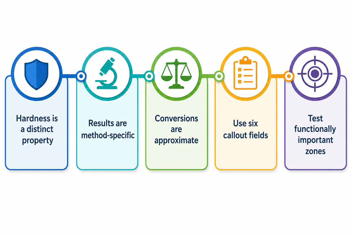
- Hardness is a distinct property from tensile strength, toughness, ductility, wear life, and machinability.
- Rockwell, Brinell, Vickers, and Knoop results are method-specific; part geometry and the zone of interest determine which test fits.
- Values listed in conversion tables are approximate equivalents only within the defined material and table scope; they aren’t exact, universal conversions.
- Quote-ready callouts contain six elements. Quote-ready callouts need six fields: These are the condition of the material, method/scale/range, location, depth intent, sampling/acceptance, and report evidence.
- One local sample may not be representative of the whole part. Sampling should be done on areas and zones that are functionally important.
| Requirement category | Minimum information | Why it matters |
|---|---|---|
| Material state | Grade, heat treatment or temper, product form | The same alloy family can produce different results after processing. |
| Measurement | Method, scale, required range, governing edition | Bare numbers cannot identify the test principle or acceptance method. |
| Part coverage | Zone, depth, locations, finished state, sampling | Local results cannot silently represent every surface or the core. |
| Evidence | Individual results, equipment verification, traceability, decision rule | “Pass” must be auditable, especially near a limit. |
| Geometry | Thickness, curvature, support, accessible test face | Geometry can rule out a familiar scale. |
| Surface | Finish, coating, preparation, indentation permission | Preparation and coatings change what is measured. |
| Conversion | Native result, table, material class, range, label | Converted values are approximate and scope-bound. |
| Revision control | Drawing, standard, specification, and report revisions | All parties must inspect the same requirement. |
| Responsibility | Design authority, manufacturer, laboratory, disposition owner | Unclear ownership delays near-limit decisions. |
What Metal Hardness Measures, and What It Does Not
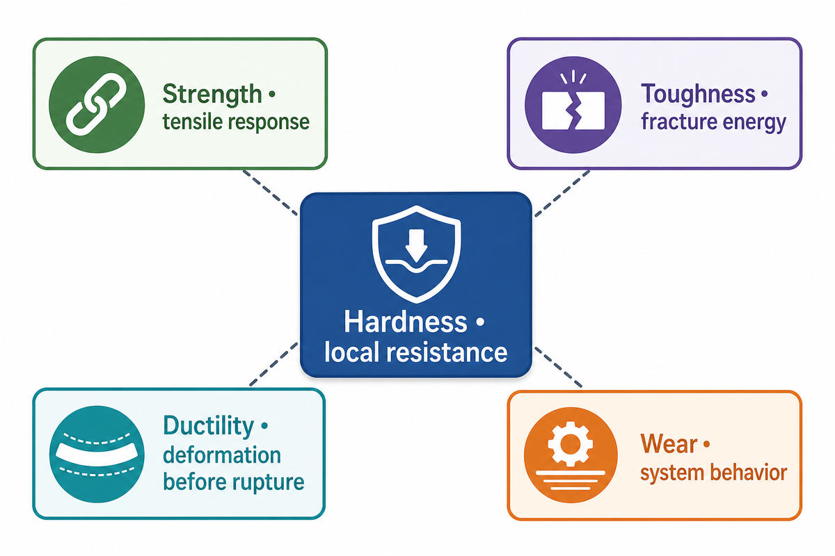
Metal hardness is determined by the resistance of a material to localized plastic deformation. The hardness of a material can be determined by several methods such as indentation, scratch, and rebound tests. Each of these tests provides information related to hardness of a material, but no single test provides enough information to rank a material with respect to all of the mechanical properties.
What is the hardness of metals?
Metal hardness is a test result rather than a fixed adjective. A hardness result provides meaning by describing the test method, scale, type of load applied, alloy condition, and the region of the metal part that was tested. Indentation hardness is primarily used for material verification and control of certain heat treatments. It can also be used to support inspection and material verification of components, but it can’t be used in lieu of tensile tests when tensile properties govern.
| Property | What it describes | What it does not prove |
|---|---|---|
| Hardness | Local resistance under a defined test | Whole-part strength, impact survival, or wear life |
| Tensile or yield strength | Response to an applied tensile stress | Indentation response at a particular surface |
| Toughness | Energy absorption before fracture | A specific hardness scale or acceptable brittleness |
| Ductility | Capacity for plastic deformation before rupture | Resistance to indentation or scratching |
| Wear resistance | Behavior in a defined wear system | A material-independent outcome predicted by one hardness number |
Bounded correlations can still be useful. Within a defined material family and condition, hardness may help estimate tensile behavior or indicate heat-treatment consistency. The mistake is turning that conditional relationship into a universal conversion or performance promise. Review metal materials for CNC parts alongside the functional property that controls the design.
Rockwell vs Brinell vs Vickers vs Knoop: Which Test Fits the Part?
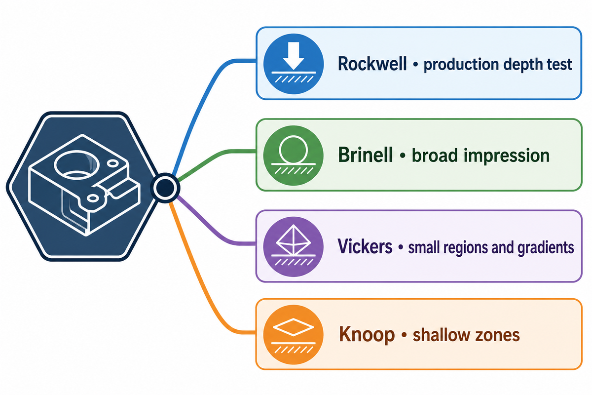
Choose a test whose indenter, load, measurement principle, preparation, and geometry fit the part. Shop scales can be unsuitable. For example, a part may have thin walls, be curved, have small features, have a coating, or have a hardened surface layer. Consideration of the principles and their application comes before evaluation of the numbers. It’s important to select the most appropriate measurement principle before determining what test to perform. Once the principle has been selected, the test can be defined.
ISO 6508-1:2023 covers regular and superficial Rockwell scales on stationary and portable machines, while also noting that product-specific standards can apply. That distinction matters: “portable” describes equipment use, not permission to ignore scale, support, curvature, or the governing product specification.
| Method branch | How it reads | Geometry questions | Typical fit | Evidence to retain |
|---|---|---|---|---|
| Regular Rockwell | Indentation depth under a defined sequence | Thickness, curvature, support, spacing, surface condition | Direct production checks when the selected scale fits | Scale, tester verification, locations, individual readings |
| Superficial Rockwell | Depth response using a superficial scale and lower test forces | Thin section or shallow zone, curvature, support, finish | Direct testing where regular scales are unsuitable and the method permits | Full superficial-scale designation, setup, verification, readings |
| Brinell hardness | Diameter of a carbide-ball impression | Adequate section and broad test face; impression acceptability | Larger-volume averaging on suitable stock or cast/forged sections | HBW designation, load/ball basis, location, image or reading record |
| Macro Vickers | Optically measured diamond-pyramid diagonals | Preparation, optical access, load, spacing, edge distance | Direct indentation where a larger Vickers test is suitable | HV designation with test force, locations, diagonal/result data |
| Micro-Vickers | Small optically measured diamond-pyramid indentation | Prepared cross-section, zone size, force, edge and spacing limits | Small regions, gradients, and qualified case-depth traverses | HV force designation, traverse coordinates, individual results |
| Knoop | Optically measured elongated diamond impression | Prepared surface, orientation, thin zone, edge and spacing limits | Small regions, brittle materials, or shallow gradients under a qualified plan | HK designation with force, traverse map, individual results |
| Portable Rockwell | Rockwell depth sequence on qualifying portable equipment | Support, access, curvature, thickness, surface condition | Large or in-situ parts when ISO 6508 or the product rule permits | Scale, equipment identity, verification, setup, readings |
| Leeb / dynamic branch | Method-specific impact and rebound response | Mass, thickness, coupling/support, orientation, finish | Field screening or acceptance only under the governing method | Native result, device verification, setup, any conversion basis |
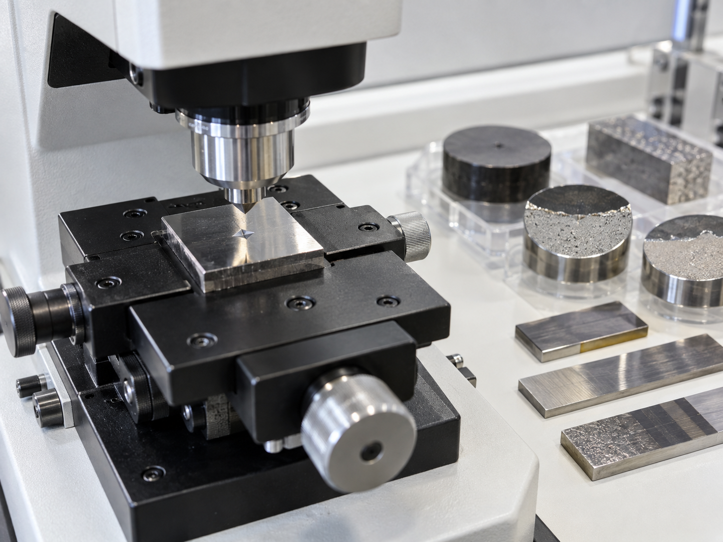
How can I check the hardness of metal?
Start by defining the zone: bulk section, surface, core, coating, or case profile. Next check thickness, curvature, finish, support, accessible area, and whether an indentation is permitted. Select the governing method and scale, prepare the surface, verify the hardness tester using appropriate reference blocks, then record the exact location and individual results. Use the hardness-test input comparator to organize those questions.
When portable, dynamic, or microhardness methods enter the shortlist
Portable instrumentation is a viable option when a bench machine is unavailable; however, the native method still matters. Leeb hardness readings, for example, are dynamic and may require a conversion; therefore, they aren’t portable Rockwell hardness readings. Microindentation hardness testing may be more applicable when the area of interest is too small for bulk testing or when a depth profile is required.
ASTM E384 describes Knoop and Vickers micro-indentation methods from 1 to 1000 gf and identifies small regions or gradients as cases of interest. This reference also shows the limitations of interpreting small indentations to represent bulk material behavior. The use of these methods on drawings requires consideration of several factors, including the capability and resources of the laboratory, the routes of specimen preparation, and the need for destructive testing.
How to Read Metal Hardness Scales Without Mixing Them
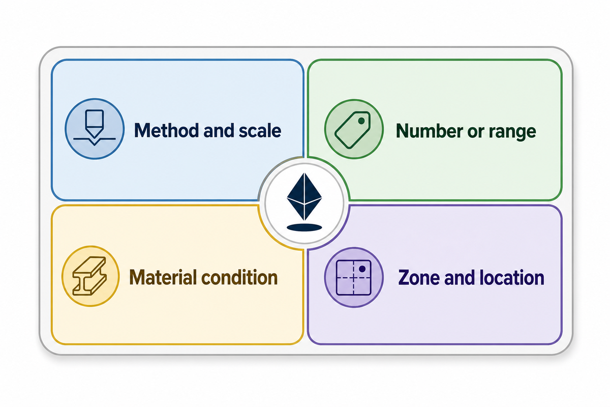
Each hardness result should consist of four parts. The four parts are the method or scale, numerical value, material condition, and test location. “58 HRC” is better, but it still lacks grade, heat-treated state, location, and acceptance context. In general, state the selected test principle and don’t combine multiple tests on the same unlabeled ladder.
1. Method and scale
Example: HRC, HBW, HV with force, or HK with force.
Example: HRC, HBW, HV with force, or HK with force.
2. Number or range
State the direct result and identify any converted value.
State the direct result and identify any converted value.
3. Material condition
Name the grade and heat treatment, temper, or delivery state.
Name the grade and heat treatment, temper, or delivery state.
4. Zone and location
Mark the face, depth, point, cross-section, and finished state.
Mark the face, depth, point, cross-section, and finished state.
The Mohs scale ranks minerals by how easily they’re scratched. It’s useful for mineral identification and relative scratch orientation, but it isn’t interchangeable with indentation hardness numbers such as HRC, HBW, or HV. However, relative scale values shouldn’t be confused with indentation hardness numbers or treated as universal conversions. Scale values shouldn’t be interchanged with hardness numbers such as HRC, HBW, and HV. Hardness charts that show the hardness of metal in industry often combine absolute hardness numbers and relative hardness numbers in the same chart. In these charts, the difference in the kind of numbers being shown is often camouflaged.
When a vendor is given a vague hardness number, a number of questions need to be asked in order to determine the hardness number’s method, material, condition, zone, and whether it’s direct or converted. Additionally, the edition of the standard and the acceptance criteria need to be determined. Only then can it be assessed whether the hardness number is representative of the component.
Why Approximate Hardness Equivalents Need Strict Scope
Values from Rockwell, Brinell, Vickers, Knoop and Leeb tests can’t be unambiguously converted to each other using a single equation. Published tables permit approximate conversion for particular materials and/or conditions. Results of tests, converted using such tables, may be used to exchange information and/or to plan tests. However, for interpretation of results, and/or for comparison of hardness values, it’s always better to rely on direct tests.
ISO 18265 states that its converted values are directly applicable only to the exact material tested; for other materials they are indicators. It also says converted values do not replace values obtained by the correct standard method, with tensile-strength estimates identified as especially unreliable. ASTM E140 likewise describes approximate relationships affected by alloy, grain structure, and heat treatment.
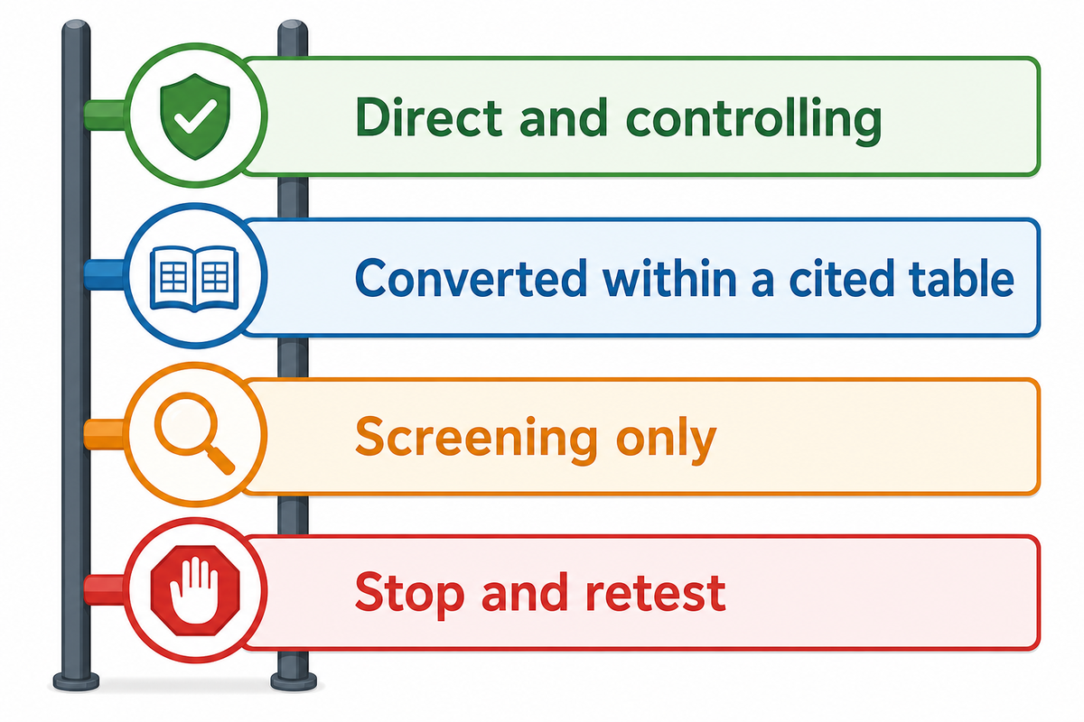
Direct-vs-Converted Hardness Acceptance Gate
- “Direct and controlling” means the part is tested according to the method and level specified in the drawing or specification.
- Converted within a cited table: The input includes the material class, condition, source table, range, and original result. The converted output is labeled “approximate converted value.”
- Screening only: the material or range is adjacent to, but not clearly within, the scope cited. It shouldn’t be released as evidence of part acceptance.
- Stop and retest: The table doesn’t cover the material, the result is near an acceptance limit, the governing contract requires a direct method, or the consequence of error is high.
Worked decision example: A shop has a large part and uses a transportable gauge to check it against an HRC note. The shop must determine the part’s native hardness result and measured condition. The shop must find the applicable conversion table, range, material condition, native reading, and contract rule. If the table is in scope, the report shows the part’s measured value and the equivalent labeled value. If there are any unknown conditions or the converted value is near the limit, the shop must perform direct measurement or provide an engineering assessment.
We don’t provide a universal hardness conversion calculator because it can mask the required conversion gates. To plan inputs, consult the method comparator and the contractually governing hardness-conversion table and edition.
Material Condition Changes the Number
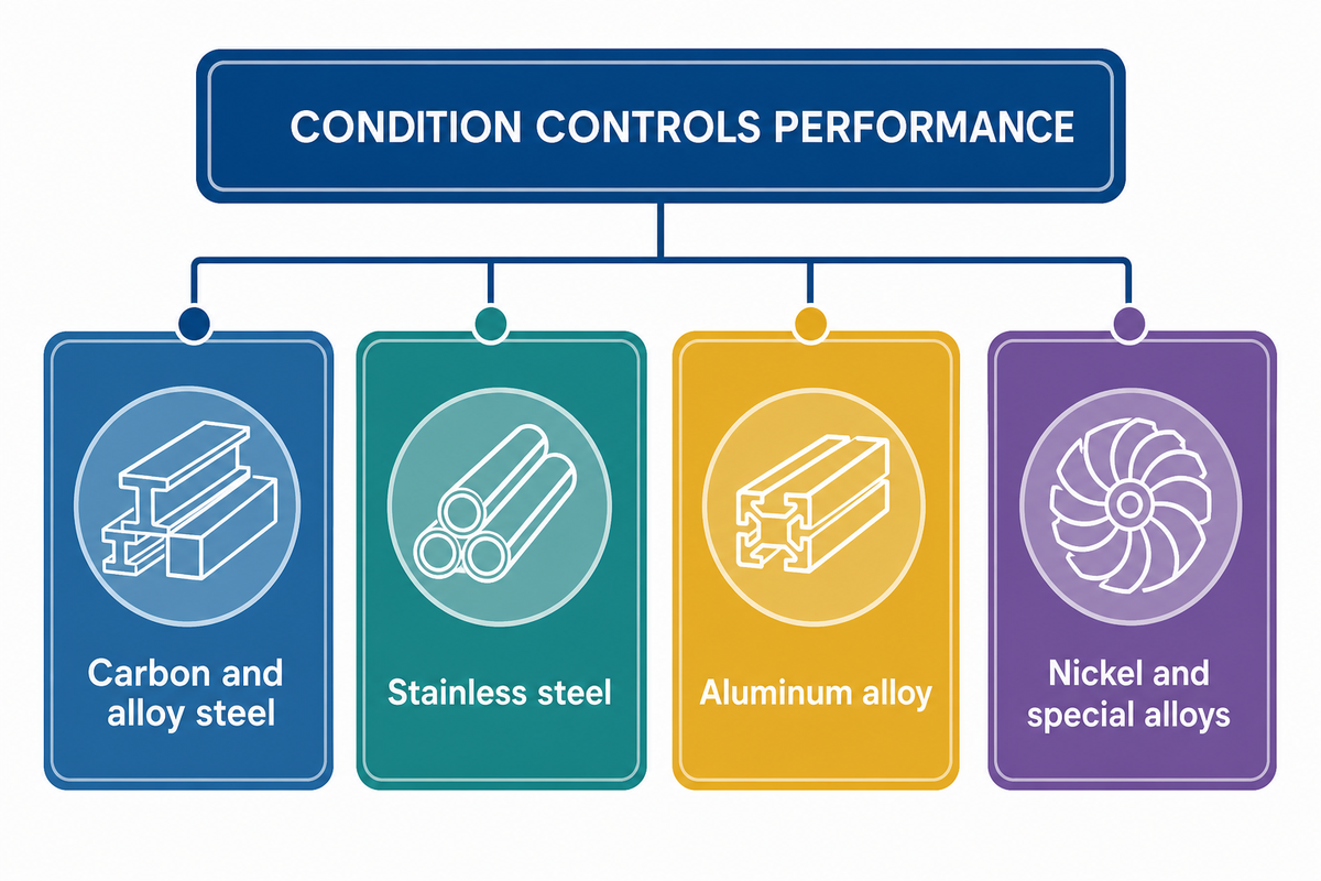
There are many factors, aside from composition, that can affect the hardness of an alloy. These include cold work, solution treatment, quench and temper processes, and aging. Welding can also affect the hardness of an alloy. Additionally, the local history of temperature can affect the hardness of an alloy. Each requirement should stipulate the alloy condition, heat treatment, and zone being tested.
Carbon and alloy steel
Annealed, normalized, quenched-and-tempered, induction-hardened, and case-hardened states can have different surface/core relationships and machining routes.
Stainless steel
Grade alone doesn’t capture solution treatment, precipitation hardening, cold work, or heat-affected zones. Corrosion and hardness requirements remain separate.
Aluminum alloy
Temper is essential. Material supplied in one condition and aged or stress-relieved later can’t be accepted from an alloy-family chart.
Nickel and special alloys
Work hardening, heat treatment, section history, and service requirements can dominate. Use the applicable material specification and qualified test route.
Zhenling’s machining experience covers materials such as carbon and alloy steels including 20#, 45#, Q235A, Q345D, 12CrMoV, GCr15, 25CrMo, and 42CrMo; stainless steels such as 303, 304/304L, 316/316L, and 321; plus nickel alloys, C276, 904L, and aluminum alloys. This material scope supports hardness testing and hardness-informed routing; however, it doesn’t mean every steel grade should share the same hardness target.
If the requirement doesn’t specify what state the stock must be in upon delivery, there’s a good chance that buyer and seller will be looking at different stock conditions upon inspection.
Surface, Core, Case Depth, and Test Location
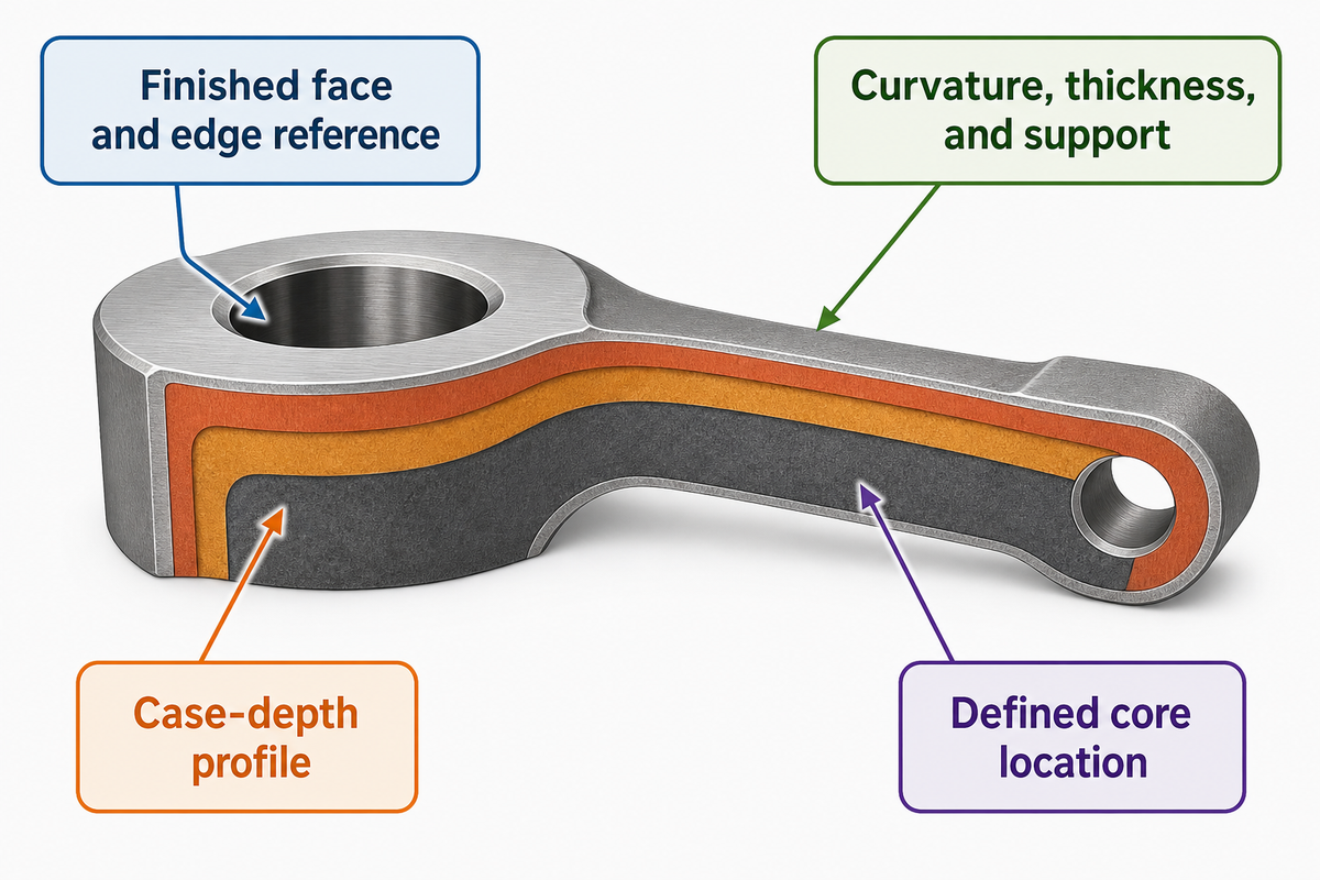
Different techniques are used to measure hardness in different locations, and hardness measurements often prompt different questions. Sample preparation and measurement techniques are also critical to understanding hardness measurement. One principal distinction is whether the required hardness evidence concerns the surface, the core, or the case-depth profile.
A surface hardness measurement provides an answer to a question about the hardness of a local volume of material. In contrast, a measurement of core hardness provides an answer to a question about the hardness of material that’s located away from the surface. Core hardness measurements evaluate sub-surface material away from the treated surface; the preparation route must be defined for the part. Case-depth hardness measurements evaluate a hardness profile from the surface toward the core rather than a region deeper than the core.
Functional surface / specified test face
Hardened case or treated layer, define the depth/profile criterion
Core zone, define where the core result is taken
Microhardness traverse: surface → case → transition → core
Microhardness traverse: surface → case → transition → core
ASTM E18-25 clearly states that results from a specific location can not be generalized to the physical characteristics of the whole part or end product. This means sample analysis must address spatial design rather than just the number of readings. There are several reasons why results from a particular location may not be representative, such as case boundaries, edge effects, decarburization, thermal history, and different thermal treatments.
- For finished work, indicate the face, distance from an edge or shoulder, angular position, and whether the indentation is cosmetically permitted.
- For a curved or thin section, also give its thickness, radius, backing/support condition and a test area large enough for the laboratory to assess method suitability.
- When evaluating a case, distinguish surface vs. effective or total case-depth acceptance. Accept the case only against the specification’s defined effective or total case-depth threshold or profile.
- In the core, define the location, specimen and whether destructive sectioning and preparation are allowed.
The use of controlled drawing language helps prevent the choice of the easiest point rather than the relevant point. The drawing-control guide should be used for locating the test zone.
How Hardness Informs CNC Machining Decisions
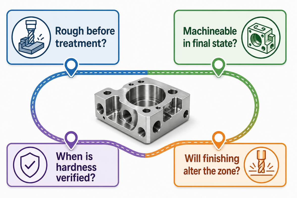
Consider hardness. It’s a routing input related to feeds and speeds, not a stand-alone feed-and-speed table. Hardness affects tool material choice, edge preparation, cutting loads, sequencing of operations, electrical discharge machining (EDM) or grinding, and when verification is performed. All other routing inputs remain relevant, including section geometry, preparation allowance, tooling, engagement, and inspection timing.
One peer-reviewed AISI 1045 milling study examined material at 38, 43, 48, and 53 HRC. In that controlled study, hardness didn’t determine the combined machinability indexes by itself; feed, tool system, milling direction, and edge preparation changed the response. Another study compared four steels at the same 54 HRC and still found different CBN tool-wear behavior associated with carbide population, metallurgy, and microstructure.
The reverse caveat also matters. In a fixed dry-turning study of AISI D2, increasing hardness from 40 to 60 ± 1 HRC increased flank wear under the tested PCBN setup. Hardness can matter strongly inside a controlled process; those data don’t supply universal parameters for another alloy, machine, tool, or engagement.
| Route question | Possible response | Evidence still needed | Ask before quote |
|---|---|---|---|
| Can geometry be roughed before treatment? | Leave finishing allowance, then treat and finish | Distortion, stock allowance, datum strategy | Which dimensions are final after treatment? |
| Is the final state machineable with the planned tool? | Hard turn/mill, grind, wire EDM, or revise sequence | Alloy/microstructure, interruption, rigidity, finish | Is the hardness uniform, local, or a case? |
| Could finishing alter the accepted zone? | Control stock removal and place final verification later | Case depth, thermal damage risk, surface integrity | How much hardened layer may be removed? |
| When should hardness be verified? | Incoming, post-treatment, post-finish, or multiple stages | Acceptance state and traceability between stages | Which result releases the finished part? |
Zhenling has CNC turning, milling, boring, grinding, wire EDM, and 3-, 4-, and 5-axis machining capabilities. The routing is specific to a drawing. Use this machinability chart as a starting point, then confirm the finished hardness state, critical dimensions, surface condition, and inspection sequence before setting process controls. Once all that’s taken into account, you can set the process controls.
The 6-Field Hardness Handoff for Drawings and RFQs
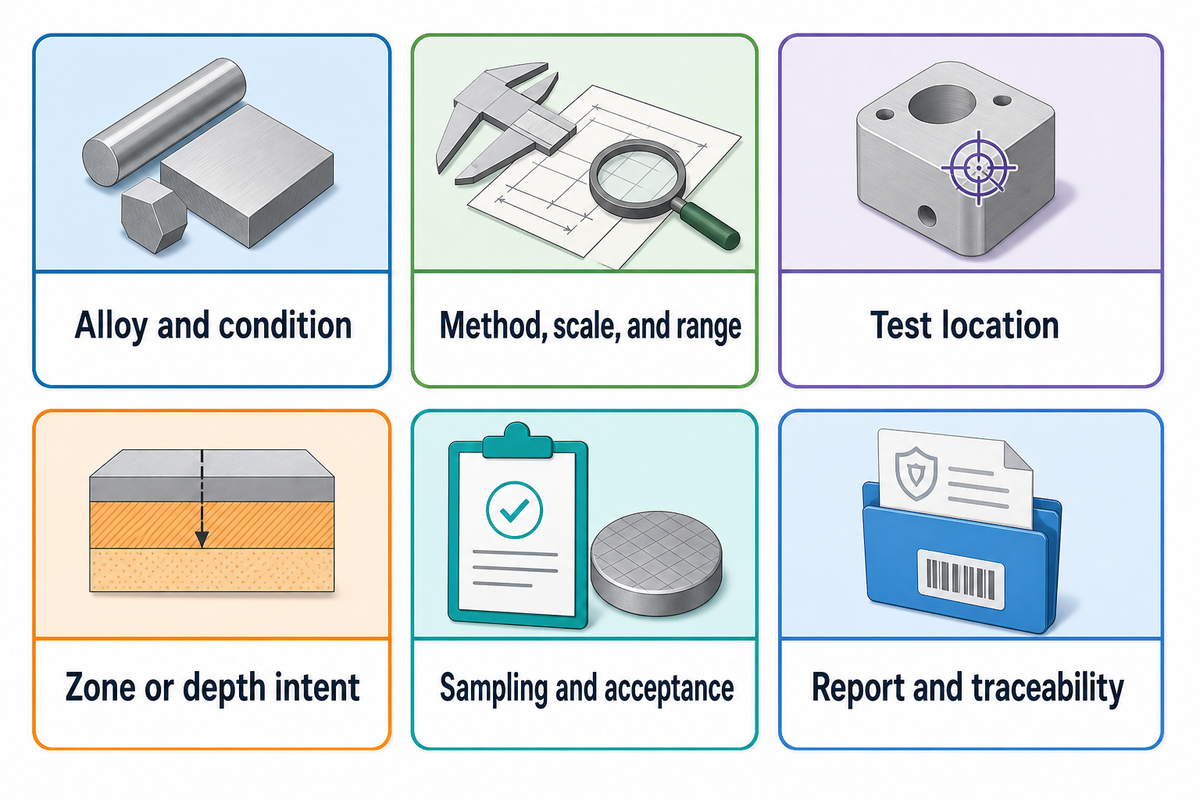
Hardness quotations contain multiple fields because missing inputs create different manufacturing and inspection assumptions.
1. Alloy and condition
Grade, product form, heat treatment/temper, and final state.
Grade, product form, heat treatment/temper, and final state.
2. Method, scale, and range
Direct method, scale designation, limits, and governing edition.
Direct method, scale designation, limits, and governing edition.
3. Test location
Marked face, point, angular position, section, and edge reference.
Marked face, point, angular position, section, and edge reference.
4. Zone or depth intent
Surface, core, coating, case threshold, or traverse profile.
Surface, core, coating, case threshold, or traverse profile.
5. Sampling and acceptance
Lot definition, parts/locations, repeat readings, and decision rule.
Lot definition, parts/locations, repeat readings, and decision rule.
6. Report and traceability
Individual results, equipment/reference chain, identities, revision, and nonconformance record.
Individual results, equipment/reference chain, identities, revision, and nonconformance record.
Incomplete note: “Hardness 50–55.”
“[Grade and final condition], [direct method/scale], [acceptance range], measured at [marked locations/zone] following [final process], by means of [Lot and Reading Plan], and reported by means of [Traceability fields], to comply with [governing Standard and Edition].”
Responsibility split: design authority sets the functional requirement and disposition rule; manufacturer confirms route and access; qualified inspection personnel confirm method suitability and report the agreed evidence.
Use the hardness drawing-note builder to structure the callout, then run the hardness-specified CNC RFQ checker before release. These tools organize inputs; they don’t replace the governing standard or engineering approval.
Have a drawing with a hardness requirement?
Specify the alloy and condition, test zone, order quantity, sampling plan, and required report across the drawing and RFQ. Also include the governing standard edition, direct method and scale, acceptance rule, surface or depth intent, final processing state, and traceability records required for release.
Verification, Sampling, Decision Rules, and Report Evidence
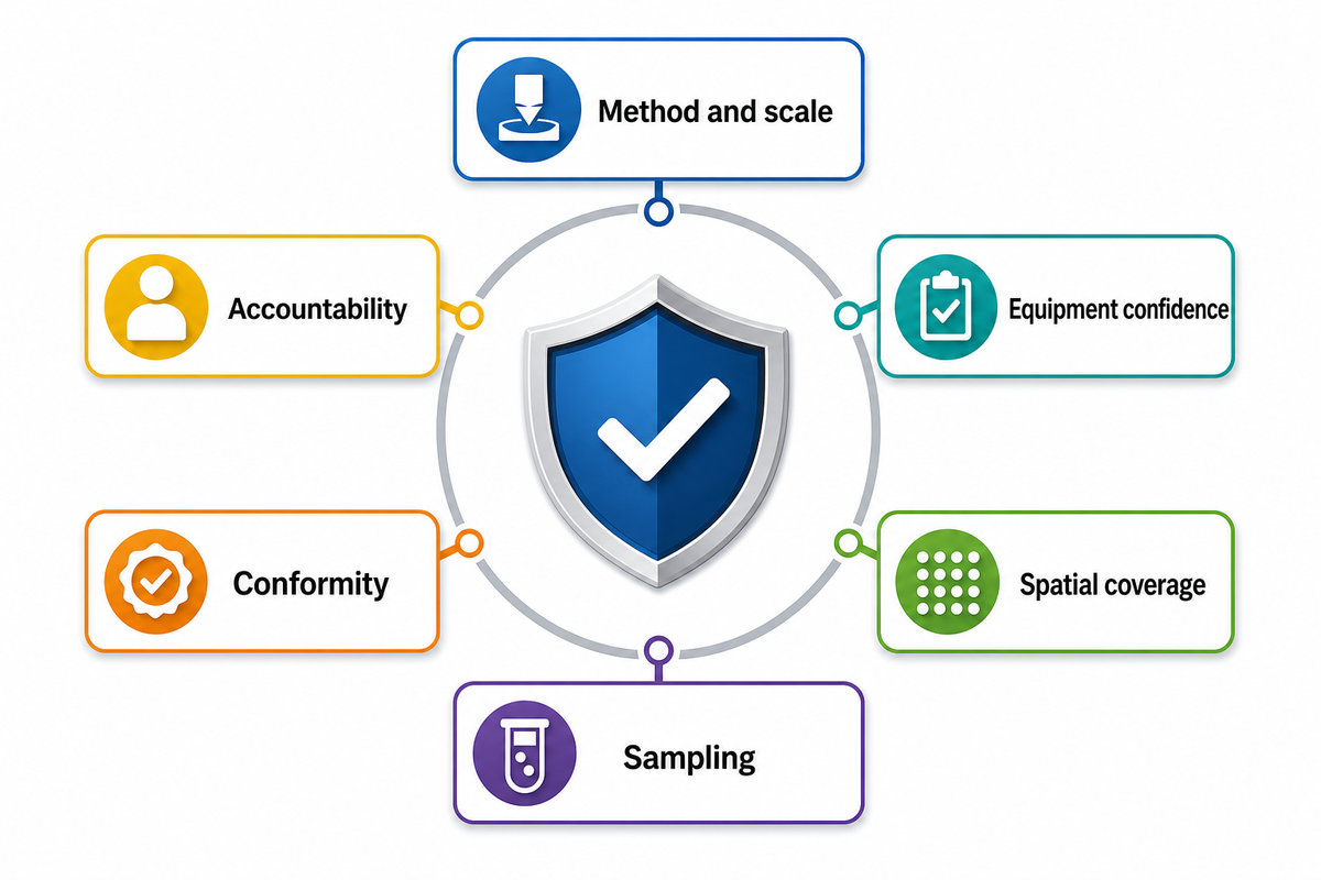
An auditable report links the requirement to the tested part, location, method, equipment chain, individual readings, sampling plan, and conformity decision. A simple statement, “Hardness passed,” for example, doesn’t enable the auditor to evaluate if the specified test lot was represented, and/or if a result near the hardness limit was also evaluated against the customer’s rules.
“Adherence to good practice should lead to reduced measurement uncertainty and improved measurement agreement.”
In the case of hardness tests, NIST explains that process and procedure matter even when the permitted hardness band is comparatively wide. A properly functioning measurement system increases confidence in the measurement actually made; it doesn’t make one location representative of the whole part.
| Requirement | Report evidence | Question it answers |
|---|---|---|
| Method and scale | Standard/edition, scale, force where relevant, direct/converted label | Was the required test actually performed? |
| Equipment confidence | Tester ID, verification status, reference-block identity and result | Was the measurement system checked for this work? |
| Spatial coverage | Part/lot IDs, marked locations, zone/depth, individual readings | What physical volume does the evidence represent? |
| Sampling | Lot definition, number of parts, locations/readings per part | How was the inspected sample linked to the order? |
| Conformity | Limits, uncertainty context, decision rule, result/disposition | How was a result near the limit judged? |
| Accountability | Date, operator/lab, approved revision, deviations and nonconformance | Who measured what, against which controlled requirement? |
Traceability of a specimen means that a measurement made on that specimen can be linked to a specific part and a specific location on that part. NIST provides Standard Reference Materials (SRM) for Rockwell C/N and Knoop/Vickers Hardness for which the metrological traceability can be established. However, this doesn’t ensure specimen traceability. Both are necessary.
Near-limit decision rule: agree before inspection how measurement uncertainty and the risk of false acceptance or false rejection will affect conformity. Values displayed just inside a limit are not automatically defensible passes if the contract requires a specific guard band or other decision rule.
EURAMET Calibration Guide No. 16, version 2.1, gives ±1.0% for user-level force application and ±0.1% of nominal force for calibration-machine application. These non-mandatory guidance values describe measurement-system performance; they aren’t a finished-part hardness tolerance. Keep equipment-calibration guidance, measurement uncertainty, and product acceptance limits in their proper layers. For broader planning, see inspection evidence and measurement planning.
Traceability Before Data Volume: What Buyers Should Ask For in 2026
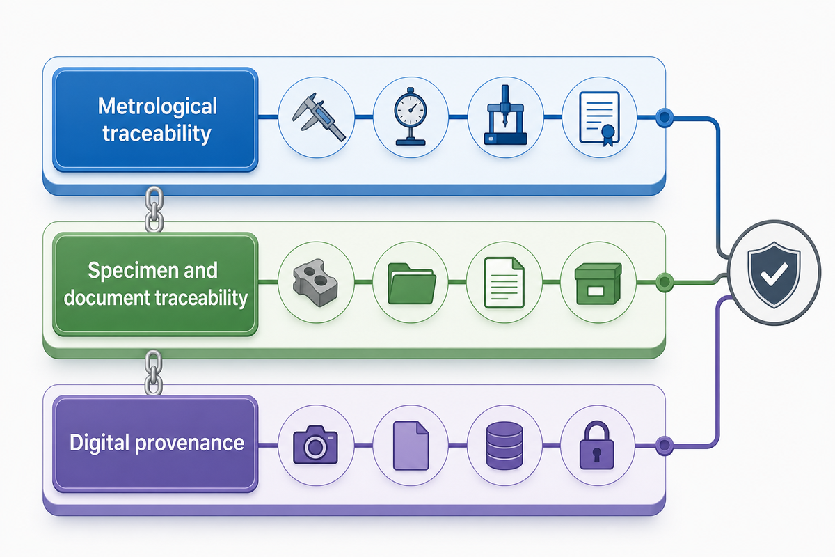
Traceability means that all three elements (digital data, specimens and test processes) be connected at all times. An indent mapping system, for example, can produce thousands of indents; however, it may not allow the customer to identify the calibration chain, reviewed revision, test location or release status.
1. Metrological traceability
Documented calibration chain, reference standards, verification, and uncertainty context for the measurement system.
2. Specimen/document traceability
Part, lot, sample, location, processing state, drawing revision, and approval identities.
3. Digital provenance
Raw result, transformations, conversion table, edits, timestamps, access, export, and final disposition.
In 2025, a trade-press article discussed hardness mapping and AI-assisted indentation evaluation, while also noting preparation, parallelism, calibration, time, cost, and interpretation constraints. It identified a number of limitations including time, cost, and the need for user expertise. The article is an example of an early technology signal, but it doesn’t indicate adoption, accuracy, or suitability for release. This technology signal doesn’t prove that the system was fully developed or suitable for release decisions. Ask these five questions: Is there a means to link measurement records to the part and location? Is the original measurement method and equipment still used and calibrated? Are measurement uncertainty, calibration status, equipment identity, and traceability preserved? Are unauthorized changes and deletions to the records, and records of revisions locked? Are complete measurement records exportable?
Frequently Asked Questions
What is the hardness of metals?
Hardness describes the ability of a material to resist localized plastic deformation and may vary from one material to another. Hardness is often characterized with respect to indentation or scratch hardness. Hardness values may depend on the condition and alloy of the material. Hardness values measured at a given location on a material don’t represent hardness values at other locations of the same material, and similarly, hardness values don’t indicate other material properties, e.g. tensile strength, toughness, or wear resistance.
How can I check the hardness of metal?
First, prioritize the evidence type you need (bulk, surface, core, coating, or case), then select a standard method that fits the part and its stated tolerances. Use suitable reference blocks to verify the test instrument according to the governing standard.
Can Rockwell, Brinell, and Vickers hardness be converted exactly?
No. Published conversions are empirical correlations for stated material classes and ranges. Label a converted result, record the original measurement, and cite the applicable ASTM E140 or ISO 18265 table and edition. If the material or range is outside scope, the contract requires a direct scale, or the result is near a limit, test directly rather than relying on conversion.
What are the five hardest metals?
Materials specification requires experience; applications may not support unrestricted ranking. For example, an “easier to machine” ranking is subjective and depends on factors such as cutting tool, surface finish, geometry, and tolerance requirements; it isn’t a wear-resistance ranking. True comparative evaluations should be limited to those properties which are relevant to the desired application. Two products of the same alloy may differ in performance due to post-processing. Thus, a product specification may not be satisfied based on simple, unrestricted rankings.
Is harder metal always more wear resistant?
1. Hardness can be one of the contributors to wear resistance; however, there are numerous other mechanisms and factors that contribute to wear. These include but aren’t limited to: abrasion, adhesion, impact, corrosion, lubrication, counterface, carbide population, toughness, surface finish, and temperature. Equal macrohardness can still produce different tool and service wear when microstructures differ.
What should a hardness drawing note include?
Add the alloy and final condition, the direct method, scale and range, marked test location, surface/core/case-depth, lot and reading plan with acceptance rule, required reports and traceability. Include the edition of the governing standard and the final condition of processing. The six fields above help expose missing inputs before RFQ release.
Does a hardness certificate prove the whole part meets the requirement?
Not automatically. The decision depends on method suitability, lot definition, sampled parts, test locations, spatial variation, depth or zone, and individual results. The decision rule could also be determined in advance. The certificate may document performed measurements. Whole-part conformity may be assessed by sampling that would be representative.
References & Sources
- NIST Recommended Practice Guide: Rockwell Hardness Measurement of Metallic Materials.
- NIST Hardness Standard Reference Materials.
- ISO 6508-1:2023, Rockwell hardness test, Part 1.
- ISO 18265:2013, Conversion of hardness values.
- ASTM E18-25, Rockwell Hardness of Metallic Materials.
- ASTM E140, Standard Hardness Conversion Tables for Metals.
- ASTM E384, Microindentation Hardness of Materials.
- EURAMET Calibration Guide No. 16, version 2.1: Hardness Measurements.
- National Park Service: Mohs Hardness Scale.
- Machinability Study of Hardened 1045 Steel When Milling with Ceramic Cutting Inserts.
- Study the tool wear of CBN tools used in hardened steel turning operations.
- PCBN tool wear in dry hard turning of AISI D2 steel.
Editorial boundary: Public standards and scope pages summarize the available editions; the contractually governing standard and edition control acceptance. Company capability statements are deemed company-provided. No universal conversion, wear-life, strength, or machining-parameter claim is made. No universal claim of part conformity is made without the governing acceptance evidence.