

How to Verify a G-Code CNC Program Before Release

Updated September 2026 · By GW
A G code CNC program is the posted instruction file prepared for a target control, machine, part, and setup; it can appear complete and ready for production while still lacking release evidence. The posted file may pertain to the wrong drawing revision. The simulation may not include a holder or fixture. The machine may have a different work offset. A first part may measure within one tolerance, but another applicable requirement may remain unresolved.
Quick answer: Verify the program as a release package, not as stand-alone code. Associate the file with the approved design and control target, simulate the actual machine environment, reconcile the setup data, review high-risk motion, and follow the qualified prove-out procedure. Evaluate inspection evidence and keep the release authority and revalidation criteria explicit.
The governing question
Do not ask only, “Does the code run?” Ask whether this exact file for this precise machine and setup provides the evidence for the authorized person to release it.
Start with the right question: is the program releasable?
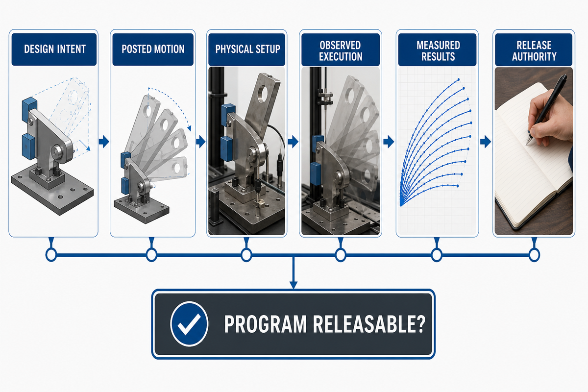
Each of the program review, simulation, prove out, inspection, and production release adds its own evidence. None of these individual processes can prove the others. A package that can be released contains design intent, posted motion, actual physical setup, observed execution, measured results, and the approved release authority.
If you require definitions, block structure, command sets, behaviors, and controller-specific references, then use Zhenling’s CNC G-code basics and controller references. This guide builds on those basics. Searches for CNC G-code simulation, G-code CNC software, a G-code CNC simulator, or M-code CNC references often mix tool selection with code-reference intent; this guide focuses instead on release evidence for one production program.
Broad G-code queries can still serve a code-reference need, so this article deliberately does not teach code definitions, command syntax, common commands, or controller-reference material. Those subjects remain on the linked Page. This guide addresses how an approved program is verified for a specific production setup.
Shops that use CNC routers or other automated machine tools may use software tools to generate G-code automatically from a CAD model. Experienced CNC programmers still troubleshoot the posted result against CNC controls because every CNC machine can implement options differently. Modern CNC machines interpret instructions in controller-specific ways, and many CNC machine configurations can change how CNC machines follow the same program. A clean animation does not prove the machine operates smoothly.
The command language known as G-code may be called the backbone of CNC, but G-code controls motion rather than proving that CNC machines can perform the released job. What makes CNC output releasable is evidence that the machine will use the intended file, setup, and acceptance basis. Those best practices are essential for anyone working with CNC machines and responsible for CNC manufacturing release or CNC operations. Parameter optimization is outside this guide.
Start with a question that can fail clearly: “What must be true before this file is allowed to control this machine for this part?” The answer is usually more than the NC file. It can include the released drawing or model, the condition of the material and stock, the postprocessor, the controller and machine configuration, tool and holder data, workholding, offsets, the inspection plan, customer requirements, and local permission.
NIST’s STEP-NC work indicates the import of the information boundary: traditional machine programs can reduce design and process information to a set of basic motion commands. The NIST publication also notes that the dynamic and non-linear nature of the material removal process may mean that some questions of suitability can’t be answered without evidence of machining. Familiarity with the code is useful; the release evidence is broader.
Key takeaway: A valid program is not automatically a released process. Define the release authority and required evidence before reviewing motion.
Freeze program identity before reviewing motion
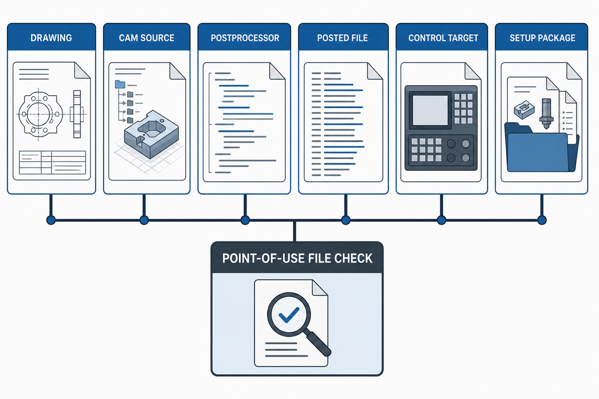
A review has value only when everyone can identify the drawing, CAM source, postprocessor, posted file, control target, and setup package, then confirm that the reviewed file reaches the machine unchanged.
Before starting the simulator, create a concise identity record. This doesn’t need to be elaborate, but must be clear.
| Item | Record | Failure it exposes |
|---|---|---|
| Product definition | Part number, drawing/model revision, approved change status | Right program for the wrong revision |
| CAM source | Project identity, operation set, tool library state | Posted output cannot be traced to reviewed intent |
| Post and target | Postprocessor version, machine, control and option set | Valid syntax with wrong machine behavior |
| Posted file | Controlled name, revision, timestamp and file digest or equivalent | Reviewed file differs from loaded file |
| Setup package | Tools, holders, fixture, stock, offsets and inspection plan | Motion is reviewed without its physical assumptions |
| Transfer integrity | Point-of-use digest, controlled transfer record, or equivalent identity check | The reviewed file is not the executed file |
| Approval boundary | Authorized role, decision basis, open conditions | A technical review is mistaken for release authority |
| Measurement basis | Characteristics, method, equipment, uncertainty and acceptance rule | A result lacks a defensible conformity decision |
| Revalidation trigger | Changes, integrity events and relevant condition drift | Old evidence remains attached to a changed process |
Revision control doesn’t solve the complete identity challenge. Transfer integrity is also an issue. A file can be approved and then copied incorrectly, replaced, edited at the control, or loaded under an ambiguous name. NIST SP 1800-10 identifies file-integrity checking, change-control management, authentication, and authorization as manufacturing-system integrity capabilities. NIST SP 1800-10 does not set a CNC program-release workflow; your implementation may be unique, and this guide’s editorial application of its integrity capabilities is to confirm the file at the point of use, not only in the programming office.
Freeze until motion review is completed on this package. If the drawing, CAM source, post, or target configuration changes, create a new review state. A new file shouldn’t have an old signature or checklist attached.
Key takeaway: Identify both the approved source package and the file actually loaded. Revision identity without transfer integrity leaves a gap.
Review the toolpath in a machine-aware simulation
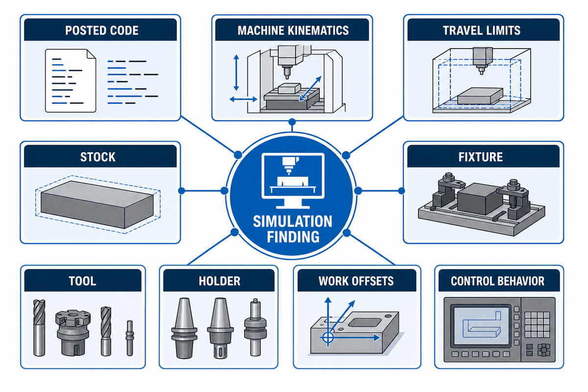
The findings of a simulation are only as good as the model contained in the simulation. The results are more meaningful when the posted code, machine kinematics, travel limits, stock, fixture, tool, holder, work offsets, and relevant control behavior match the intended production context.
To start, document the simulation boundaries. Was the NC file posted or was the CAM path simulated? Was the posted code interpreted? Was the model of the machine complete and did it include fixtures and holders? Did the modeled stock match the actual blank and its orientation? A good animation doesn’t answer these questions.
| Finding | Useful conclusion | Remaining question |
|---|---|---|
| No modeled collision | The interpreted path clears represented geometry | Was all relevant geometry and state represented correctly? |
| Collision warning | A modeled interference needs investigation | Is it physical risk or a model/configuration error? |
| Correct remaining stock | The modeled removal follows the defined stock and operations | Do actual stock, tools, offsets and material behavior match? |
| Cycle completed | The simulated interpreter reached the planned end | Does the target control implement every relevant function the same way? |
A 2024 peer-reviewed study on simulation-based collision detection offers a good example of a simulation boundary. The paper identifies the authors with Leibniz University Hannover’s Institute of Production Engineering and Machine Tools and acknowledges Germany’s Central Innovation Program for SMEs and project partners as funders of the Apollo research project. The sensor-coupled method achieved 96.87% accuracy for three defined reference workpieces, yet it also produced a false collision. The authors didn’t present the results for a broader scope of the simulation. The number doesn’t reflect a universal simulation accuracy.
The authors of the same paper explain that wrong tool lengths, workpiece origins, and clamping may be absent in an offline model. Conversely, an incorrect bounding box may produce a false collision. Until the modeled environment is aligned with the machine, none of the results are reliable.
Do release reviewers need to know G-code to verify CAM output?
CAM software can generate G-code automatically from a CAD model, but the release reviewer should confirm the intended control, machine, and setup before use. The review starts at that output boundary. The release owner must identify the target control and machine, check the postprocessor, review critical modes and transitions, interpret warnings, and know when current OEM documentation is required. The goal isn’t code memorization. It is enough control-language literacy to detect a contradiction between the posted program and manufacturing context.
Literacy should be used for verification and not treated as another level of syntax. During release verification, a reviewer may need to confirm how CAD and CAM intent is translated into the posted file and whether the target interpreter, control options, and machine configuration support that file. This guide treats those factors only as release assumptions; it does not teach G-code commands or programming. In a lathe or machining center, confirming whether the posted file corresponds to the approved machining process is far more important than treating CNC programming as a self-contained guarantee.
Key takeaway: Record what the simulator knew. A result is only as broad as the machine, setup, state and interpreter represented.
Reconcile the controller, tools, offsets, stock and workholding
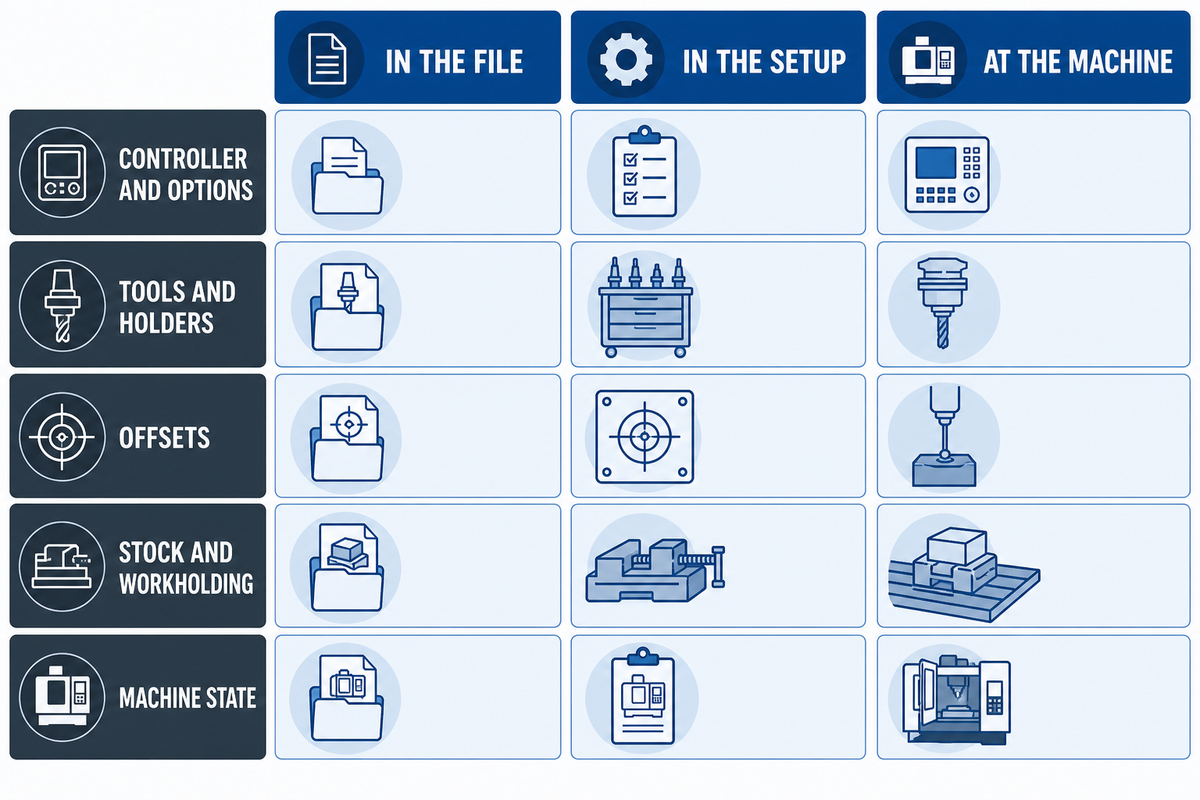
A posted program can be internally consistent and correct while its external assumptions can be incorrect. Reconciliation is the process of comparing these assumptions to evidence from the target machine and actual setup before the controlled execution.
Use an assumption matrix rather than relying on memory. Read the program and setup package side by side, and verify each item at the machine through the qualified process. The matrix should distinguish “present in the file,” “defined in the setup,” and “observed at the machine.” A matching label isn’t sufficient if the underlying value or geometry differs.
- Controller and options: target model, software state, enabled functions, units, coordinate and compensation behavior, cycles, macros and machine-builder customizations.
- Tools and holders: tool number, assembly identity, cutting geometry, gauge length, diameter or radius data, orientation, life status, and holder envelope.
- Offsets: work coordinate, tool length, wear, rotary-center or other pertinent records, including the person who set the record and the associated setup.
- Stock and CNC Workholding: material condition, size of the blank, orientation, clamping location, fixture or jaw geometry, support, accessibility, and potential deformation.
- Machine State: target axes, movement extent, home/reference position, attachments, pallets, probes and state of machine, fixture, and control system components that may affect the interpreted path.
Official simulation products describe the same need from a software perspective. Hexagon’s NCsimul product documentation says the product verifies actual G-code with a digital twin of the CNC machine. That is the vendor’s description of the intended function; it doesn’t confirm that a particular user’s twin is complete. The release record has to still specify the digital machine, tools, stock, fixture, and control system data.
Address issues at their source. If an offset is discrepant, don’t simply edit the checklist. Determine whether the file, setup plan, tool assembly, measurement, or machine record is incorrect, then repeat the necessary reviews. Small discrepancies often lead to larger issues.
Key takeaway: Reconcile the program with observed machine context. An assumption that exists only in CAM is not yet production evidence.
Gate risky motion before a controlled first run
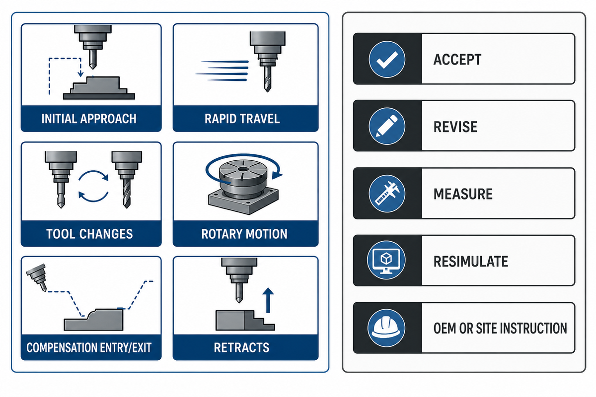
Independent motion review should focus on transitions of high consequence or low visibility: initial approach, rapid travel near stock or fixtures, tool changes, plane or mode changes, rotary motion, compensation entry/exit, retracts, cycle boundaries, and final safe state.
This isn’t an exhaustive risk list. The risk is in the relationship between motion, machine, geometry, and state. Mark each transition, show the evidence and set a disposition. The disposition can be accept, revise, measure, resimulate, or defer to current OEM or site instruction.
The peer-reviewed study on collision detection mentions setup-origin and tool-length errors, and states that not all of these errors may be picked up by existing simulations. It also notes that changes to NC code, in the absence of a new collision check, can reintroduce risk. Therefore, a motion gate shouldn’t accept “the earlier simulation passed” after a file, setup, or tool change.
Don’t adopt a generic rapid percentage, clearance distance, feed override, or air-cut height from an article as a machine instruction. ISO 16090-1:2022 provides machine-class safety scope for numerically controlled milling machines and machining centres, but it does not supply one universal prove-out value. The current machine-builder instructions, risk assessment, qualified site procedure and competent personnel control the operating method.
Key takeaway: Review high-consequence transitions with their actual evidence. Never convert a generic article value into a machine instruction.
Prove out under the machine builder’s and shop’s procedure
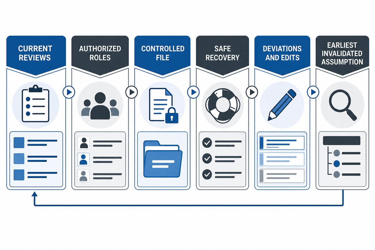
Prove-out is done in accordance with the current machine-builder and site instructions by authorized, competent persons. It tests the relationship between the reviewed file and the physical machine. Prove-out doesn’t replace simulation, setup reconciliation, or inspection.
A useful article-level sequence is intentionally non-numeric:
- Confirm that the identity package, simulation disposition, setup reconciliation, and motion-risk review are current.
- Confirm who’s authorized to lead, observe, stop, change and approve the prove-out.
- Load and verify the controlled file at the machine. Set up the machine and achieve the state required by the qualified procedure.
- Under the applicable qualified method, follow the instructions for controls, observation, stop criteria and safe recovery.
- Evidence your deviations, edits, changes in offsets and physical observations. Don’t rely on your shop-floor memories.
- After any change, return to the earliest verification assumption that the change invalidated.
The UK regulator HSE states that adequate training under work-equipment rules varies with the job, worker competence, circumstances and equipment. Its training and competence guidance points to manufacturer instructions, supervised instruction and competent experienced staff as relevant inputs. That’s why a generalized method can describe decision gates but can’t authorize a reader to operate an unfamiliar machine.
Site procedures may include equipment-specific tools such as single-block operation, feed or rapid override, dry run, distance-to-go displays, machine locks, graphics, or an air cut. Because the availability and meaning of each of these methods may vary, they should be considered site specific equipment and procedure methods. Stop when the observed state departs from the reviewed state, not only when a collision alarm appears.
Key takeaway: Prove-out is qualified work, not a recipe. The current OEM and site procedure defines the operating controls and stop conditions.
Use first-part inspection as one release input
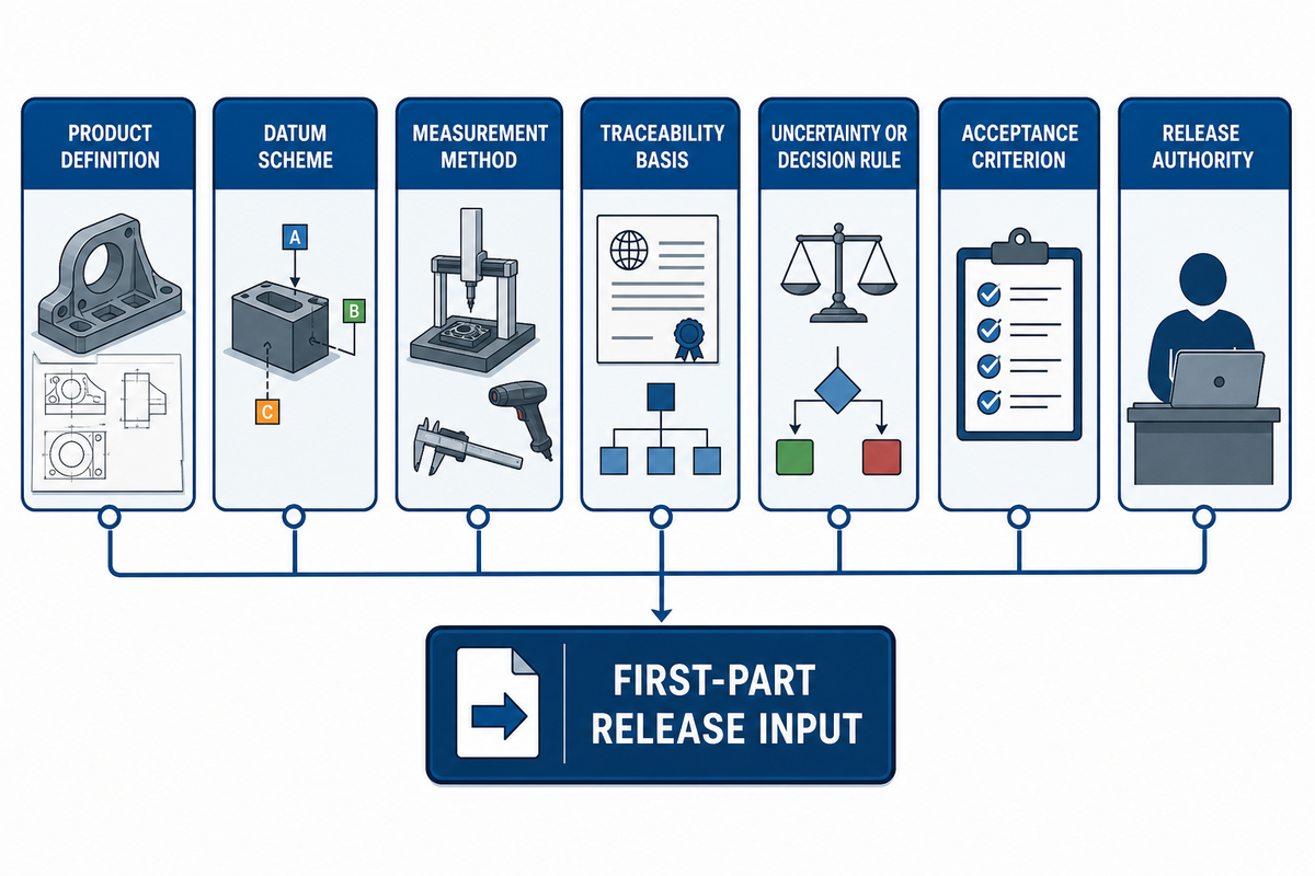
A first-part result can connect actual output to the released revision, but it doesn’t automatically prove every customer, statutory, regulatory, measurement-system, or sustained-process requirement. Release needs an explicit acceptance basis and an authorized decision.
The dimensional inspection record should be created from the product definition. Critical and risk-related characteristics, the datum scheme, measurement method, equipment, resolution, calibration or traceability basis, uncertainty or decision rule (if applicable), result, acceptance criterion, nonconformance disposition, program and setup identity should be identified. If the first part prompted a correction, bind the new result to the corrected file and repeat the affected gates.
This is clear in SAE AS9102C:2023: first-article inspection requirements don’t replace customer requirements and applicable statutory and regulatory requirements. This limited principle can also be useful in a non-aerospace sector, without making AS9102C itself applicable. The principle is that inspection evidence should answer the acceptance criteria; it shouldn’t provide broader authority.
Measurement is associated with uncertainty. According to NIST’s metrological traceability guidance, traceability in measurement is the property of the result through a documented calibration chain. Traceability in measurement doesn’t guarantee fitness for purpose. The uncertainty associated with the measured value must be suitable for the measurement need.
The record should provide context and detail about the units and decision points, not just report the result. The following entries are synthetic formatting examples only; they aren’t tolerances, acceptance limits, machine settings or measurements of real parts. These examples show how the nominal, observed, limit, and uncertainty fields can be distinguished when a release package is reviewed.
| Evidence category | Synthetic field string | What the real record must identify |
|---|---|---|
| Linear size | 25.000 mm | 24.996 mm | 0.010 mm | 0.003 mm | Nominal, result, applicable limit and stated uncertainty |
| Feature location | 50.000 mm | 50.004 mm | 0.012 mm | 0.004 mm | Datum reference, axis, result and decision basis |
| Hole feature | 8.000 mm | 7.998 mm | 12.000 mm | 0.003 mm | Characteristic identity, measured depth/diameter and method |
| Form result | 0.050 mm | 0.032 mm | 0.004 mm | 0.002 mm | Specification, observed result, resolution and uncertainty |
| Orientation result | 0.030 mm | 0.021 mm | 0.004 mm | 0.002 mm | Controlled feature, datum scheme, result and decision rule |
| Runout result | 0.040 mm | 0.028 mm | 0.003 mm | 0.002 mm | Rotation basis, setup identity, instrument and result |
| Angular result | 90.000° | 89.995° | 0.010° | 0.004° | Nominal angle, observed result, limit and uncertainty |
| Surface result | 3.2 μm | 2.8 μm | 0.4 μm | 0.2 μm | Parameter, cutoff/method, result and acceptance basis |
| Ambient condition | 20.0 °C | 20.7 °C | 0.5 °C | 0.2 °C | Observed condition, relevant range, sensor and time |
| Question | Evidence | Boundary |
|---|---|---|
| Was the correct feature measured? | Revision, characteristic and datum trace | One feature does not cover omitted requirements |
| Is the decision method adequate? | Method, equipment, traceability, uncertainty and rule | A displayed number is not absolute truth |
| Does the result match the released process? | File, setup, material and inspection identities | Later changes can invalidate the link |
| Who can release? | Customer/sector/site approval rule | The CNC Program Release Assurance Rail framework is not release authority |
How does CNC machining ensure high quality?
CNC machining quality isn’t about code alone. Quality involves controlled design inputs, effective equipment, suitable tooling and workholding, verified setup information, qualified personnel, process monitoring, measurement, and control of nonconformance and feedback. For repeat production, one conforming first part doesn’t describe variation of subsequent parts. Use the first part as an evidence check point. Then apply the sampling, control, and release criteria applicable to the product, customer, and sector.
Key takeaway: First-part inspection informs release. It does not replace the applicable acceptance system or prove sustained process capability by itself.
Revalidate after changes, integrity events, or condition drift
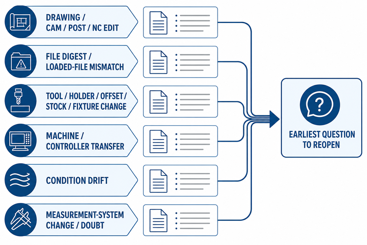
Revalidation is required when the evidence no longer represents the current file, setup, machine, measurement system, or physical condition. Formal revisions are just one of the many triggers.
Use one editorial rule. Return every change to the earliest gate whose assumption it invalidates.
This editorial rail isn’t an industry standard. It’s designed to prevent a later pass from masking an upstream mismatch.
| Event | Earliest question to reopen | Possible downstream work |
|---|---|---|
| Drawing, CAM, post or NC edit | Is this still the approved identity package? | Repost, resimulate, reconcile, prove out and reinspect as impact requires |
| File digest or loaded-file mismatch | Did the reviewed file reach the machine intact? | Quarantine, restore controlled file and repeat affected checks |
| Tool, holder, offset, stock or fixture change | Does the model and setup evidence still match? | Update models/data, review motion and requalify physical execution |
| Machine or controller transfer | Is the post/control/machine target still valid? | Repost or revalidate the full target-dependent chain |
| Wear, thermal, vibration, spindle or axis drift | Does current physical condition still support the evidence? | Assess condition, correct, re-establish setup and inspect affected output |
| Measurement-system change or doubt | Is the conformity decision still trustworthy? | Reassess method, uncertainty, traceability and prior decisions |
Condition drift is of concern because it may happen without a document being changed. NIST’s manufacturing-maintenance work notes that machine-tool wear can cause unknown performance changes and unanticipated downtime. In this guide’s editorial framework, that makes condition drift a revalidation trigger; shops should define which monitoring and condition evidence they retain with revision records for repeated production.
Set revalidation ownership and evidence retention before releasing. Otherwise, a shop-floor adjustment can turn into a materially different process, and every original approval remains visually “green”.
Key takeaway: Reopen the earliest invalidated assumption. Changes, integrity loss and physical drift all count.
Package evidence for a supplier or customer handoff
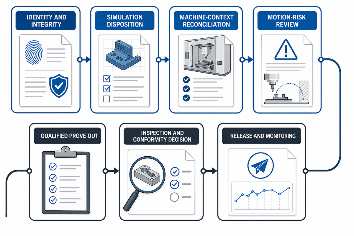
A proportionate evidence handoff lets another qualified party identify the released design, program, machine context, deviations, inspection evidence, approval boundary, and revalidation triggers without exposing unnecessary proprietary process detail.
Using the seven gates checklist is a helpful way to determine what’s needed. However, adjust it to suit the contract, risk, and confidentiality:
- Identity and integrity: released product definition, program identifier, post/target identity, and confirmation that the executed file matches the reviewed file.
- Simulation disposition: what was modeled, what wasn’t, major warnings, and their resolution.
- Machine-context reconciliation: confirmation that tools, holders, offsets, stock, fixture, and relevant machine state matched the approved setup.
- Motion-risk review: identified high-consequence transitions and the evidence used to accept or revise them.
- Qualified prove-out: responsible roles, procedure identity, deviations, edits, and stop/recovery records as applicable.
- Inspection and conformity decision: revision-bound results, method, and applicable acceptance basis.
- Release and monitoring: the authorized decision, open conditions, approved change controls, condition-change triggers, and the rule for repeating evidence.
Zhenling claims experience with drawing and sample-based custom machining across CNC turning, milling, grinding, boring, wire cutting EDM. They also claim to have experience with 3-5-axis machining centers and carbon and alloy steels, stainless steels, nickel alloys and aluminum. These capabilities come from the supplier. This only indicates that a specific program, tolerance, material route, or verification package hasn’t been confirmed until a review for the specific job has been completed. Buyers can place that evidence request in the context of Zhenling’s custom CNC machining services.
A buyer may not always need the supplier’s complete CAM file, postprocessor or the unique setup method. The goal is to present sufficient controlled evidence to understand what was released, against which requirements, by whom, and what would invalidate it. It’s better to agree on this evidence before production, rather than reconstruct it after a nonconformance.
Key takeaway: Ask for traceability and decision evidence, not a generic statement that “the program was checked.”
Frequently asked questions
What is the difference between G-code review, simulation and prove-out?
Read the answer
G-code review examines the posted instructions and their control context. Simulation interprets motion against a defined digital model. Prove-out observes controlled execution on the physical machine under an approved procedure. Although they overlap, they can’t replace each other. Code review can overlook geometry, a simulation can ignore the real-world effects, and a prove-out without controlled identity can test the wrong code. Inspection evaluates defined product characteristics and doesn’t prove that each upstream process was correct.
Can a simulator guarantee that a CNC program is safe to run?
Read the answer
No general simulation result can guarantee safety. It can provide a lot of evidence in the context of the machine, controls, stock, fixtures, tools, holders, offsets, and states. Incomplete or incorrect inputs can hide a real risk or produce an unjustified warning. Safe execution also depends on current OEM instructions, the site’s risk controls, competent people, actual machine condition, and an authorized prove-out process.
Do release reviewers need to write G-code by hand?
Read the answer
CAM systems can post programs automatically, especially for complex geometry, so release reviewers do not need to write every block by hand. However, the responsibility for release still requires sufficient control and code knowledge to verify the target, review critical states and motions, interpret alarms or warnings, and identify the need for a qualified examination of the postprocessor or machine-specific functions prior to release.
Why do G-code programs behave differently on different controls?
Read the answer
Controller implementations and machine-builder options can vary. Often, a code that’s supported on one machine can behave differently on another. Verify behavior and configuration against current documentation for the target control and machine.
When should a CNC program be revalidated?
Read the answer
When something happens that causes a break in the connection between current production and previous evidence, revalidate. This includes drawing or CAM edits, posting, coding, postprocessor or controller changes, a mismatch in transfer integrity, tool or holder substitutions, offsets, changes in stock or material condition, fixture changes, a machine being moved, a change in a measurement system, and wear, thermal, or vibration conditions, spindle or axis drift, or other developments. Restart from the first affected gate instead of repeating everything or taking an unacceptably old approval.
What evidence should a buyer request with a first article?
Read the answer
Specify the revision number, program number/setup number, the characteristics measurement, measuring method and acceptance criteria, the measured result, any deviations, approval status, and the conditions for revalidation. Please note, the scope of the information depends on the contract, sector, and level of risk. This first-article report is a supplement to, not a replacement of, other customer requirements, statutory and regulatory requirements, and production control requirements.
CNC Program Release Assurance Rail
Bind identity and transfer integrity → simulate the defined machine context → reconcile the physical setup → review high-consequence motion → perform qualified prove-out → make an uncertainty-aware inspection and conformity decision → authorize release with change and condition monitoring. This is an editorial decision framework, not an industry standard or machine operating procedure.
How this guide was built
The research method uses official NIST and safety sources, a peer-reviewed CNC collision-detection study, customer-specific quality context, current trade coverage, and qualitative machinist experience. The manuscript has been separated from Zhenling’s G-code basics to avoid confusion. The named CNC Program Release Assurance Rail is editorial synthesis; Zhenling capability statements are first-party disclosures; no universal crash-reduction, cost-saving, clearance, override, or defect-rate claim is made.
References & Sources
- Tying Together Design, Process Planning and Machining with STEP-NC Technology, National Institute of Standards and Technology
- End-to-End Quality Information Framework Technology Survey, National Institute of Standards and Technology
- NIST SP 1800-10: Protecting Information and System Integrity in Industrial Control System Environments
- Simulation-based collision detection for CNC machining using sensor-based image recognition, Procedia CIRP, 2024
- ISO 16090-1:2022 Machine tools safety, Machining centres, milling machines, transfer machines
- Training and competence for work equipment, UK HSE
- AS9102C: Aerospace Series, First Article Inspection Requirements, SAE International, 2023
- Metrological Traceability: Frequently Asked Questions and NIST Policy, National Institute of Standards and Technology
- Enhancing Maintenance Strategies for Manufacturing Operations, National Institute of Standards and Technology
- NCsimul product documentation, Hexagon
- Control technology update, Manufacturing News, 2024
Code-reference boundary: The linked basics page covers G-code and M-code, including G00 and G01, feed rate, spindle speed, drill cycles, tool changes, coordinate systems, and the programming language used to control CNC machines. It explains how lines of G-code direct tool movement, how CAM software can generate G-code automatically from a CAD model, and why experienced CNC programmers still troubleshoot the posted result against CNC controls. Readers learning CNC programming can use that reference; this guide instead verifies the posted file, machine tool, and physical release evidence.
For readers still building an understanding of G-code, the basics of G-code explains how G-code and M-code work as CNC code: G-code for CNC supplies G-code instructions that tell the machine to move the tool, while certain G codes instruct the machine when to start, stop the machine, or change the spindle rather than merely describe turning the spindle. A CNC control uses G-code, and CNC machine tools can use CAM software for g code programming; that programming to control a machine still has to be checked before asking the machine to perform a fast move. The reference can tell the machine to move in a tutorial example, but this guide checks whether the released program, machine context, and evidence support an authorized decision. It is not a lesson on the machine on how to move or on how fast to move, and it does not replace the shop procedure for deciding how the machine moves.
ABOUT ZHENLING
Custom machining from drawings and samples
Shanghai Zhenling Hardware Co., Ltd. was established in 2006. Its Jiashan, Zhejiang factory covers an 8,000 m² site with a 6,000 m² workshop for custom machined metal parts.
The team works from drawings and samples for applications including pressure vessels, oil-gas separation, and fluid control. Material experience includes carbon, alloy, and stainless steels as well as special alloys.
- 3-, 4-, and 5-axis CNC machining
- Grinding, wire cutting, and welding
- Domestic and export divisions
CONTACT PROFILE
Company details
- NAME
- Shanghai Zhenling Hardware Co., Ltd.
- ESTABLISHED
- 2006
- LOCATION
- Jiashan, Zhejiang, China
- FOCUS
- Custom machined metal parts from drawings and samples
- CAPABILITIES
- 3/4/5-axis CNC machining, grinding, wire cutting, and welding
- CONTACT
- Share the drawing, material, quantity, and critical requirements.



