By XCX · Updated September 2026
Short answer.
contact vs optical inspection cnc parts is a feature-level decision. Contact methods physically sample selected surfaces; optical methods capture non-contact image, profile, or surface data. The better route depends on the feature, datum, access, surface, tolerance, and evidence required for acceptance.
Accuracy, speed, and appropriateness can’t be determined by considering method names only. A camera used for cosmetic screening is not automatically a dimensional measuring system, and a touch probe is not automatically appropriate for every bore, thin wall, or freeform surface.
Key takeaway
Choose the sensor after defining the feature question. If different sensors answer different questions, combine them only under a controlled datum, reporting method, and conflict rule.
This document offers trade-off guidance for different sensory modalities without applying generic evaluation metrics to an unknown part.
Quick Specs
Decision unitOne controlled feature or characteristic
Required inputsDrawing, datums, tolerance, access, surface, report need
Possible routesContact, optical, or qualified multisensor
Final controlTask evidence plus an agreed decision rule
Contact vs Optical Inspection at a Glance
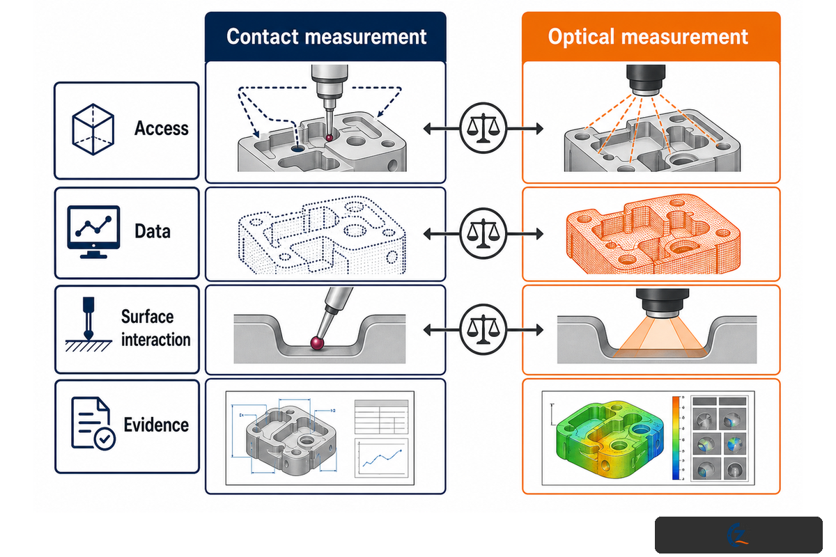
Contact inspection obtains data by means of a stylus or probe in physical contact with the part. Optical inspection does not contact the part and obtains data by means of optical sensors. Contact and optical inspection do not guarantee that all part features can be evaluated by both inspection methods. The terminology describes sensing approaches, not a guaranteed uncertainty, throughput, or acceptance capability for every application.
Contact measurement
- Physically samples selected surface points
- Can establish datums and reach suitable internal geometry
- Requires stylus access, qualification, and controlled force
- Produces point or scanning data under a defined strategy
Optical measurement
- Captures edges, profiles, or surfaces without contact
- Can collect dense data on visible, accessible areas
- Requires line of sight, focus, contrast, and surface control
- Varies by imaging, distance-sensing, and optical 3D class
The optical umbrella matters: imaging probes, distance sensors, and optical 3D systems do not share one universal claim. ISO 10360-13:2021, for example, has a defined optical 3D scope rather than covering every vision device.
| Question | Contact route | Optical route | Verify first |
|---|---|---|---|
| Access | Stylus path and safe approach | Clear line of sight and focus | Feature geometry and fixture |
| Data | Selected points or contact scan | Edges, profiles, or dense surface data | Sampling and fitting rules |
| Surface interaction | Force, deflection, contamination | Reflectivity, contrast, occlusion | Actual material condition |
| Evidence | Qualified probe and task method | Qualified optical class and task method | Uncertainty and decision rule |
Since a Coordinate Measuring Machine (CMM) can integrate multiple types of sensors, the name doesn’t specify the type of sensor integrated. On-machine inspection is one factor that can influence CMM placement, and it is a platform decision that may share influences absent from an independent inspection.
Do not collapse three decisions
Cosmetic defect detection asks what’s visible. Dimensional measurement asks what value describes a defined feature. Conformance then asks whether that result, its uncertainty or capability basis, and the governing rule support acceptance.
When Contact Inspection Is the Stronger Route
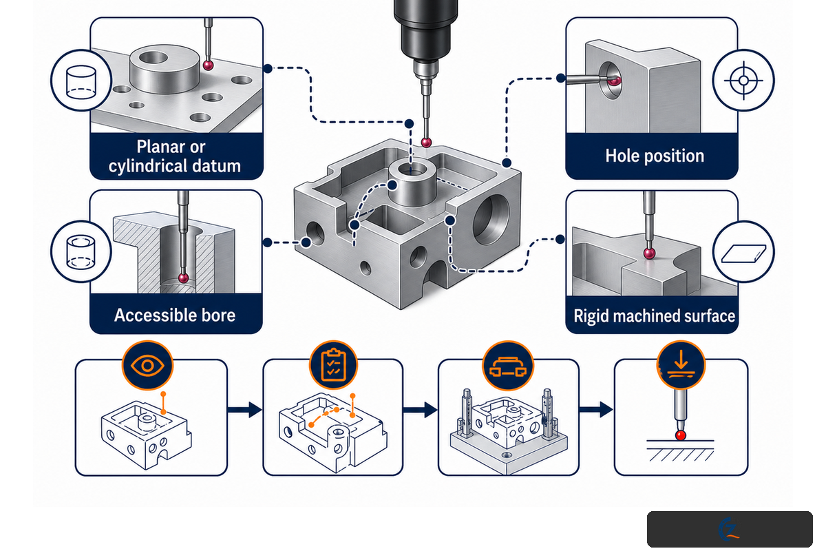
Contact inspection often provides a strong means of defining datums and may suit bores or geometric relationships that require physical sampling. It may also provide a means of establishing features, relationships and constraints which can be defined by physical contact. This method of definition requires that the stylus be able to access the feature, the probe be qualified, the fixture be stable, and contact with the feature not change it in any way.
| Feature situation | Why contact may fit | What to verify |
|---|---|---|
| Planar or cylindrical datum | Physical points can realize a controlled alignment | Point layout, restraint, datum simulation |
| Accessible bore | A qualified stylus can sample internal walls | Tip size, depth, approach, qualification |
| Hole position or feature relation | Measurement can remain tied to the datum frame | Alignment, sampling, fitting algorithm |
| Rigid machined surface | Contact may be stable on a clean surface | Burrs, debris, force, local form |
Negative aspects of a process are just as important as the positive aspects. In this application, a long stylus can create access concerns, sparse points can miss local form, and a compliant part can move under contact. NPL Good Practice Guide 130 treats task-specific uncertainty as more than a machine value; NISTIR 5170 (https://nvlpubs.nist.gov/nistpubs/Legacy/IR/nistir5170.pdf) likewise treats CMM uncertainty as measurement-specific. In precision manufacturing, uncertainty can be managed by pairing a calibrated gauge with feature-specific metrology inside precision machining process control.
What is a CNC inspection?
A CNC inspection is a controlled verification of specified machined part characteristics against the applicable drawing, model, specification, and quality plan. It can occur during setup, after a critical operation, during production, or before release; it is not limited to one machine or to final inspection.
A useful inspection record connects
Part and revision → characteristic and datum → method and setup → nominal, tolerance, actual result, and units → acceptance status and disposition authority.
A contact result becomes useful acceptance evidence only when its feature, alignment, method, and decision basis are clear.
NPL’s task-specific guidance is a practical reminder: evaluating the measurement task requires the workpiece, strategy, environment, and measuring system to be considered together, not as isolated catalog entries.
When Optical Inspection Is the Stronger Route
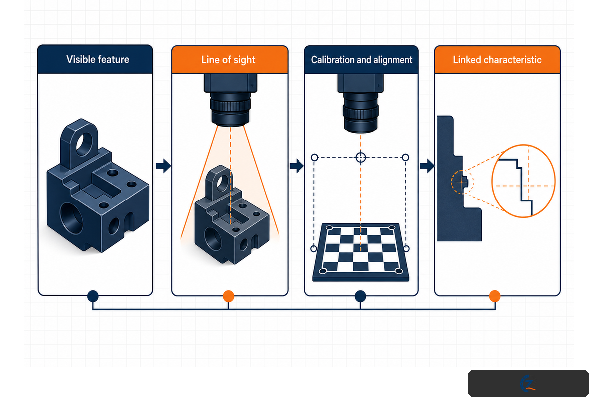
In various situations, optical inspection provides a number of advantages. These situations may include visible features that are impractical to access with a mechanical probe, small features, or a dense distribution of surface features; the optical system still needs line of sight. However, an optical sensor is only as good as the environment it’s operated in. An optical sensor won’t be able to capture features that are too small for it to resolve.
GlareReflective metal can saturate or shift the observed edge; validate lighting and surface response.
OcclusionA visible exterior profile does not prove a hidden wall or deep bore is measurable.
FocusDepth, magnification, field of view, and feature resolution must suit the actual geometry.
Edge definitionBurrs, texture, coating, illumination, and algorithms can move the detected boundary.
Optical surface capture, edge imaging, and visual defect screening, while related, address discrete issues. NPL Good Practice Guide 39 places image formation, calibration, illumination, focus, and edge detection inside a dimensional vision method.
Dense data is not automatic truth
A large point cloud can describe an accessible surface in detail, yet the result still depends on calibration, alignment, filtering, registration, surface response, and the definition of the characteristic being reported.
Production Machining considers non-contact vision for small-part production; however, that application does not establish universal limits on inspection size, speed, or capability.
Optical validation artifact
Record sensor class, calibration basis, orientation, illumination, surface, resolution basis, algorithm, and the linked characteristic.
Accuracy Depends on the Measurement System, Not the Sensor Label
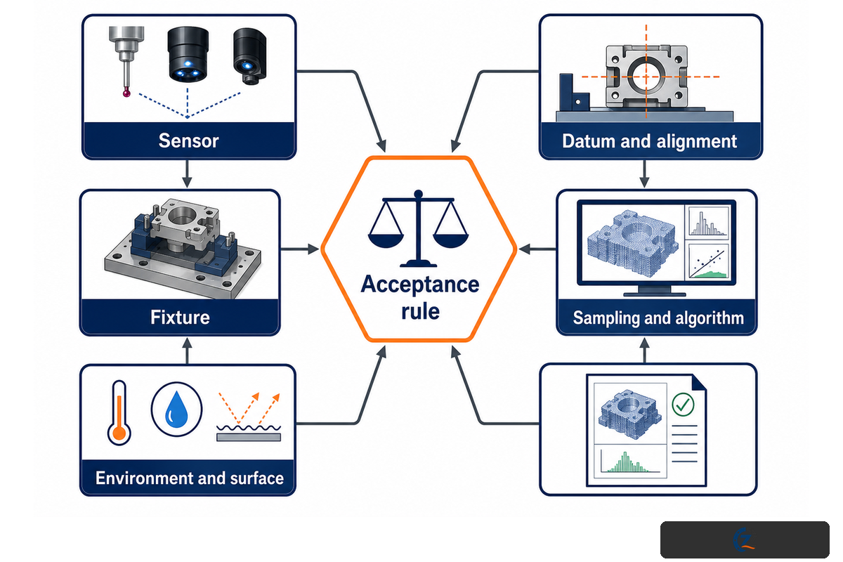
Fitness for acceptance in contact and optical inspection of CNC parts depends on the complete measurement system: sensor, datum alignment, fixture, sampling and algorithm, environment and surface, plus the uncertainty or capability basis and decision rule.
6-Variable Measurement-System Check
1. SensorQualified type, range, resolution, probing behavior, and calibration status.
2. Datum and alignmentHow measured features establish the coordinate system.
3. FixtureSupports, clamps, orientation, cleanliness, and possible deformation.
4. Sampling and algorithmPoint locations, scan path, filtering, fitting, and edge rules.
5. Environment and surfaceTemperature, vibration, finish, reflectivity, contamination, and stabilization.
6. Acceptance ruleUncertainty or capability basis, rounding, guard band, and disposition owner.
The Six-Variable Measurement-System Check distinguishes resolution, repeatability, machine performance, and task uncertainty. NISTIR 5170 likewise treats CMM uncertainty as measurement-specific rather than a machine label.
Specification does not equal result uncertainty
A resolution value, acceptance-test result, or maximum permissible error can be relevant evidence, but none automatically becomes the uncertainty of a finished-part feature measured with a particular fixture, alignment, point strategy, environment, and evaluation rule.
Either path can fail for a number of reasons, including using the wrong datum, part movement, surface behavior that defeats sensing, or an evaluation that answers a different question.
Independent-verification boundary
On-machine probing supports process feedback; the quality plan decides whether separate acceptance evidence is required.
For broader method scoping, review the site’s dimensional inspection scope. That page can frame the service conversation, while the controlled drawing and feature-level measurement plan remain the authority for the part.
Use the Feature-to-Sensor Route Map
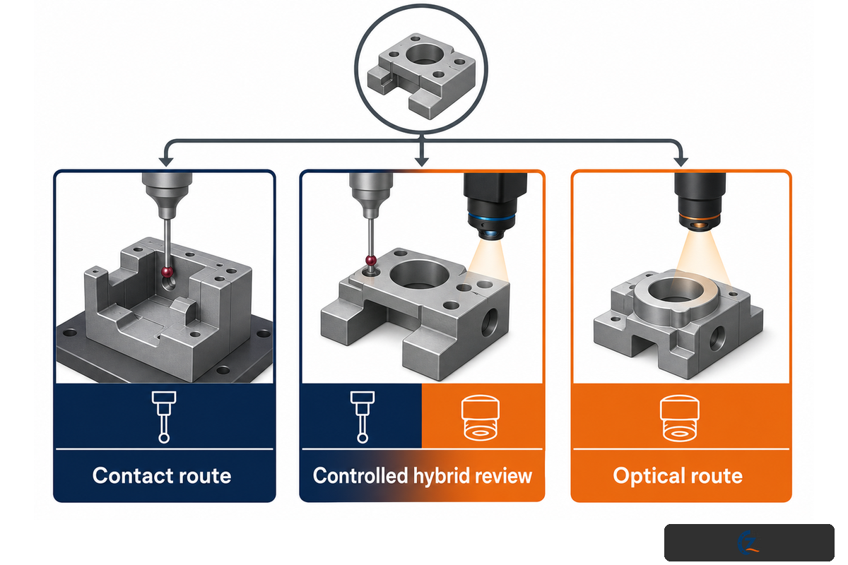
Evaluate features and not machines. The Feature-to-Sensor Route Map sends datums and suitable hidden geometry toward contact evaluation, accessible profiles and dense surfaces toward optical evaluation, and acceptance-critical overlaps toward a controlled hybrid review.
| Feature type / question | Candidate route | Why | Verify first |
|---|---|---|---|
| Bore diameter | Contact; optical if qualified access exists | Internal wall sampling | Depth, tip/optical path, fit method |
| Hole position | Contact or qualified optical | Datum-related center evaluation | Datum realization and edge definition |
| Planar datum | Contact or validated surface method | Coordinate-frame establishment | Point distribution and surface state |
| Thread or groove | Feature-specific contact or optical | Complex boundary and access | Stylus path, focus, evaluation model |
| Freeform surface | Optical or contact scan | Dense shape comparison | Registration, occlusion, filtering |
| External profile | Optical | Visible edge and repeated geometry | Focus, contrast, burrs, algorithm |
| Burr or cosmetic defect | Optical screening | Appearance and presence detection | Defect definition; dimensional boundary |
| Soft or thin feature | Optical or low-force validated contact | Reduce method-induced movement | Restraint, force, surface response |
| Free-state feature | Validated low-restraint route | Avoid changing part condition | Support rule and reporting state |
Path validation doesn’t guarantee a method. Geometry, tolerances, access, condition of the material, resolution, and report evidence can impact the route chosen.
Route each CTQ with a reason
For every critical-to-quality characteristic, write: candidate sensor → feature-access reason → setup condition → validation evidence → reporting field → disposition owner.
The route also includes broad RFQ language. Examples include “optical” and “contact” and describe different sensor and sampling techniques that could be used to implement the feature.
Turn the map into a controlled plan
Use the site’s inspection method selector as a practical handoff, then bind the choice to the current drawing, characteristic IDs, setup, and acceptance evidence.
When a Hybrid Contact-and-Optical Strategy Makes Sense
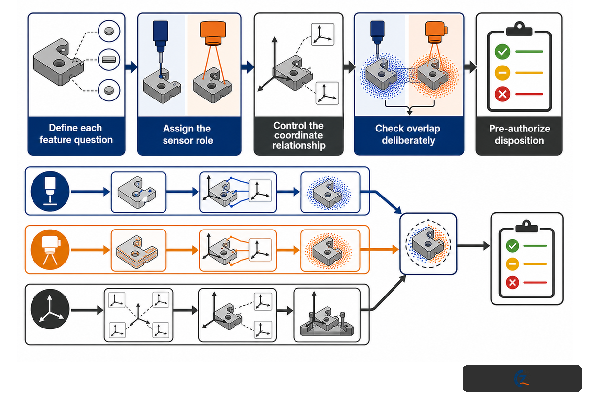
Hybrid inspection works when contact and optical sensors answer different feature questions in one controlled coordinate and acceptance system. Contact sensors may define a datum or evaluate suitable internal geometry. Optical sensors may capture accessible profiles or dense surface data. Together, they answer complementary feature questions. A duplicated feature needs a defined conflict-resolution process.
- Define each feature question — state the characteristic, tolerance, datum relation, and acceptance purpose.
- Assign the sensor role — record why contact, optical, or both provide suitable evidence.
- Control the coordinate relationship — preserve the datum, registration, fixture, and transformation basis.
- Check overlap deliberately — select correlation features and comparable evaluation settings.
- Pre-authorize disposition — name the decision rule and owner before results disagree.
The CMMs described in ISO 10360-9:2013 (https://www.iso.org/standard/54523.html) are capable of both contact and non-contact probing. ISO 10360-9:2013 covers CMMs with multiple contacting and non-contacting probing systems and supplements, rather than replaces, the tests for individual probing systems.
| Ledger field | Record before disposition |
|---|---|
| Feature and requirement | Characteristic ID, nominal, tolerance, datum reference |
| Contact result | Value, units, setup, sampling and uncertainty/capability basis |
| Optical result | Value, units, sensor class, setup, algorithm and uncertainty/capability basis |
| Setup difference | Alignment, fixture, surface, filtering, temperature, timing |
| Decision | Comparable-measurand finding, rule applied, owner and disposition |
The Two-Sensor Conflict Ledger prevents choosing the value closer to nominal before proving both systems measured the same thing.
Hybrid rule
Use two sensors when their roles are complementary, their coordinate relationship is controlled, and conflicting evidence has a defined investigation and disposition path. More data without those controls isn’t automatically more confidence.
Define the CNC-Part Inspection Scope Before the RFQ
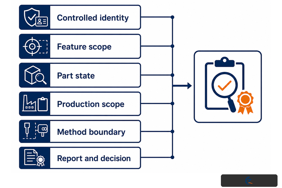
Scope statements define the level of detail that a supplier should infer about a product when creating an offer. An absence of a scope statement could cause suppliers to interpret the level of measurement for which they would be responsible differently and potentially issue quotes containing discrepant language for what’s meant by “inspection.”
RFQ checklist — copy these fields into your quote request:
| Parameter | Required entry | Why it matters | How to verify |
|---|---|---|---|
| Controlled identity | Part, model/drawing, revision | Prevents obsolete-scope quotes | Revision-controlled file list |
| Feature scope | Datums, CTQs, nominal, tolerance, units | Defines the measurands | Ballooned drawing or characteristic list |
| Part state | Material, finish, coating, restraint condition | Changes sensing and geometry | Process-stage and condition record |
| Production scope | Lot quantity, sampling, frequency, stage | Sets labor and decision timing | Approved quality or sampling plan |
| Method boundary | Mandatory or supplier-proposed route | Prevents silent substitutions | Method proposal and validation evidence |
| Report and decision | Data fields, format, rule, approver | Makes acceptance auditable | Sample report and approval workflow |
Start with CNC metrology planning, then use the dimensional RFQ checklist to freeze the inputs. These resources organize the discussion; they do not replace the drawing owner, contract, or applicable inspection procedure.
| Planning area | Terms to define in the controlled scope |
|---|---|
| Part definition | cnc machined parts, cnc components, precision parts, part geometry, and tight tolerances |
| Dimensional objective | dimensional accuracy, parallelism, irregularity, tolerance requirements, and quality requirements |
| Surface objective | surface roughness, surface finish, surface quality, surface condition, and finish requirements |
| Method family | optical metrology, cmm inspection, vision measuring, metrology systems, and visual inspection |
| Feature interaction | contact surfaces, measuring surfaces, surface defects, optical application, and measuring tools |
| Manual checks | micrometer checks and other high accuracy methods selected for the stated inspection requirements |
| Production stage | incoming inspection, shop floor verification, production environments, production time, and cycle time |
| Data control | inspection data, quality data, repeatable execution, reliable quality, and quality control |
| Automation boundary | State whether results are captured without manual intervention and how machining quality is reviewed. |
Made-to-print review boundary
Zhenling can review supplied drawings and requirements, but that isn’t an uncertainty statement, equipment promise, lead time, or acceptance authority.
Zhenling makes a series of made-to-print items from ferrous and nonferrous materials, including the supplied carbon and alloy steels, stainless steels, nickel-based alloys, and aluminum alloys. Early inspection planning with the customer may be required when material, operating conditions, or assembly change what the customer must verify.
Send a controlled inspection brief
Attach the current drawing and identify the features, tolerances, production stage, sample plan, report fields, and acceptance owner you expect the quotation to cover.
Read the Measurement Report Before Accepting the Part
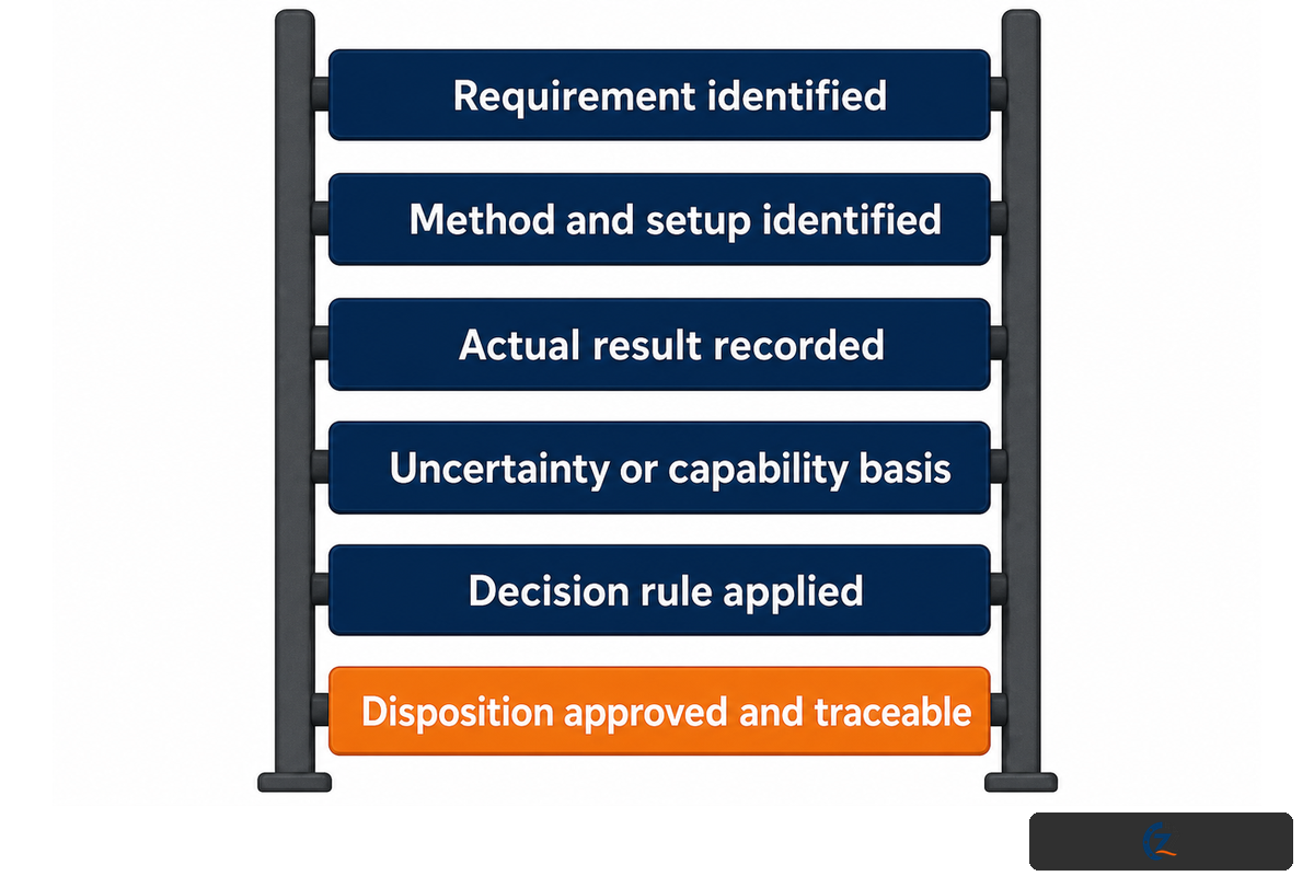
A measurement report must disclose the revised part, the feature reported, the applicable tolerance, the means and setup used to take the measurement, the measurement result and uncertainty or capability basis, the decision rule, and the person or authority who accepted the report.
The entries below are report-syntax examples only, not Zhenling specifications, inspection results, or suggested acceptance limits.
| Data type | Requirement entry | Actual-value entry |
|---|---|---|
| Diameter | 25.000 mm | 24.998 mm |
| Position | 0.050 mm | 0.038 mm |
| Flatness | 0.030 mm | 0.021 mm |
| Roughness | 1.6 µm | 1.4 µm |
| Angle | 90.0° | 89.9° |
| Pressure | 10.0 bar | 10.1 bar |
| Temperature | 20.0 °C | 20.4 °C |
| Speed | 1000 rpm | 998 rpm |
| Frequency | 50.0 Hz | 49.9 Hz |
| Voltage | 24.0 V | 24.1 V |
| Current | 2.0 A | 1.9 A |
| Mass | 1.00 kg | 0.99 kg |
A bare PASS can hide whether contact and optical methods used different datums, filters, surface preparations, or rounding rules. ISO 14253-1:2017 addresses decision rules for proving conformity or nonconformity with specifications, making the decision basis a controlled part of acceptance rather than an afterthought.
Pass/fail evidence ladder
Requirement identified → method and setup identified → actual result recorded → uncertainty/capability basis stated where required → decision rule applied → disposition approved and traceable.
What should I do if a CNC measurement is out of tolerance?
Before disposition, the accepted measurement report must be checked for the feature, units, datum, part state, measurement method, fixture, qualification status, and decision rule. Contain the affected part or lot under the applicable procedure and preserve the original result for traceability.
Recheck without erasing evidence
Preserve the original result and repeat only under an approved plan. If another sensor is used, reconcile the measurand, alignment, sampling, surface, uncertainty basis, and decision rule.
Escalate the result to the drawing owner, customer, or authorized quality function as required. Provide evidence to support controlled sorting, deviation, rework, scrap, concession, or additional sampling decisions. The measurement team should not determine commercial or engineering authority.
Better automation still needs a controlled decision
Connected and multisensor workflows can move information faster, but automation doesn’t settle what was measured, whether the result is fit for purpose, or who may accept a borderline or conflicting result.
Review Zhenling machining capabilities for first-party manufacturing context. Next, provide controlled part information. The best way to initiate a supplier discussion is to provide evidence for the measured feature and explain its requirement, not to ask the supplier to declare one sensor universally better.
Ready for a feature-level review?
Share the drawing revision, CTQs, datums, material and surface state, quantity, inspection stage, report format, and acceptance requirements.
Frequently Asked Questions
Use the information provided to construct a feature-and-evidence framework without advocating that either compared sensor is universally superior.
The information contained herein responds to the most frequent types of problems encountered in the machining industry.
Is optical inspection more accurate than contact inspection?
Short answer
Not by default. Accuracy belongs to a defined task, not a sensor label. Geometry, alignment, fixture, surface, sampling, algorithm, environment, uncertainty, and the conformity rule all matter. Compare the stated evidence for the actual feature and tolerance, including what result is reported and who owns the acceptance decision under the governing quality procedure.
Can optical inspection measure deep bores and hidden features?
It depends on access
Only when the optical path, focus, and sensor geometry can reach and resolve the feature. Direct-view vision may measure an accessible edge yet miss a deep internal wall. Specialized optics or tomography are different systems with different evidence; conventional hidden geometry often remains a contact candidate. The report should name the sensor class, view, focus, feature boundary, and validation basis.
Can a touch probe damage or distort a CNC part?
Contact can affect compliant parts
Yes, when force or fixturing is unsuitable for a soft, thin, flexible, or delicate part. Probe behavior, stylus, approach, stiffness, wall thickness, and restraint matter. Validate the actual feature and consider qualified non-contact measurement if touching changes its condition, alignment, surface, or reported geometry during the controlled dimensional inspection process.
When should CNC parts be inspected?
Tie each checkpoint to a decision
Inspect at the checkpoints tied to release or process-risk decisions. The quality plan should define frequency, sample size, escalation, records, and reaction.
What should a CNC machining inspection report include?
Identify the requirement, result, and decision
Identify the part, lot, revision, feature, nominal, tolerance, result, units, method, and disposition. For critical acceptance, add the datum and alignment, relevant uncertainty or capability basis, material environmental conditions, sensor or probe identity, fixture, program or algorithm reference, decision rule, report approval, and authority for resolving borderline or nonconforming results.
Can contact and optical results disagree?
Yes; investigate comparability first
Yes. Different locations, datums, surfaces, or filters can produce different evidence. Without a common measurand, setup, and rule, two results remain two datasets.
References & Sources
- National Physical Laboratory, Good Practice Guide 39: Dimensional Measurement Using Vision Systems
- National Physical Laboratory, Good Practice Guide 130: Co-ordinate Measuring Machine Task-Specific Measurement Uncertainties
- National Institute of Standards and Technology, NISTIR 5170: Estimating Uncertainty in CMM Measurements
- ISO 10360-13:2021: Optical 3D coordinate measuring systems
- ISO 10360-9:2013: CMMs with multiple probing systems
- ISO 14253-1:2017: Decision rules for proving conformity or nonconformity
- Production Machining: Examining Non-Contact Inspection for Small-Part, High-Volume Production