CNC Workholding: A Force-Path Guide to Fixtures and Clamping

CNC TOOLING GUIDE
The effectiveness of a workholding method relies on the datum, support, force path, access envelope, and proof that exist after cutting and releasing.
Quick Answer, Choose the Force Path Before the Fixture Name
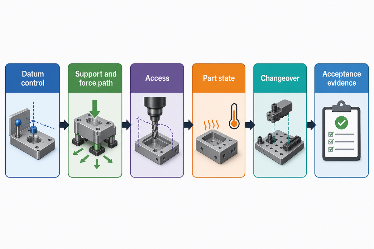
CNC workholding is a system that locates, supports, restrains, and verifies a workpiece relative to a machine tool. More specifically, start with the functional datums and the following operation, and then select a vise, chuck, collet, modular plate, zero-point interface, vacuum or magnetic fixture, or a dedicated fixture. The answer is the one that retains contact securely through the cutting loads without excessive deformation, and still leaves adequate clearance for the cutter, probe, chips, operator, and inspection. The CNC machine needs that entire workholding solution, not just a clamp on a machine table.
- Datum control: Which part datums must be re-established, and where do they reside in the machine coordinate system?
- Support and force path: Where does the cutting load enter and where does it travel into supports and the machine?
- Access: Can the tool, holder, probe, coolant, chips, fasteners, and operator access the required section?
- Part state: Will variation of the blank, thin walls, residual stress, heat, and stock removal affect stiffness?
- Changeover: Does the setup need repeatable pallets, powered actuation, sensing, or will a simple manual load be sufficient?
- Acceptance evidence: What seating, force/load, trial-cut, released-state, and inspection records release the setup?
Use the workholding approach selector after sketching this six-gate path. It eliminates some choices and narrows the discussion without misleading anyone into thinking a product name defines a finished system.
Locate, Support, Then Clamp, The Datum-to-Clamp Trace
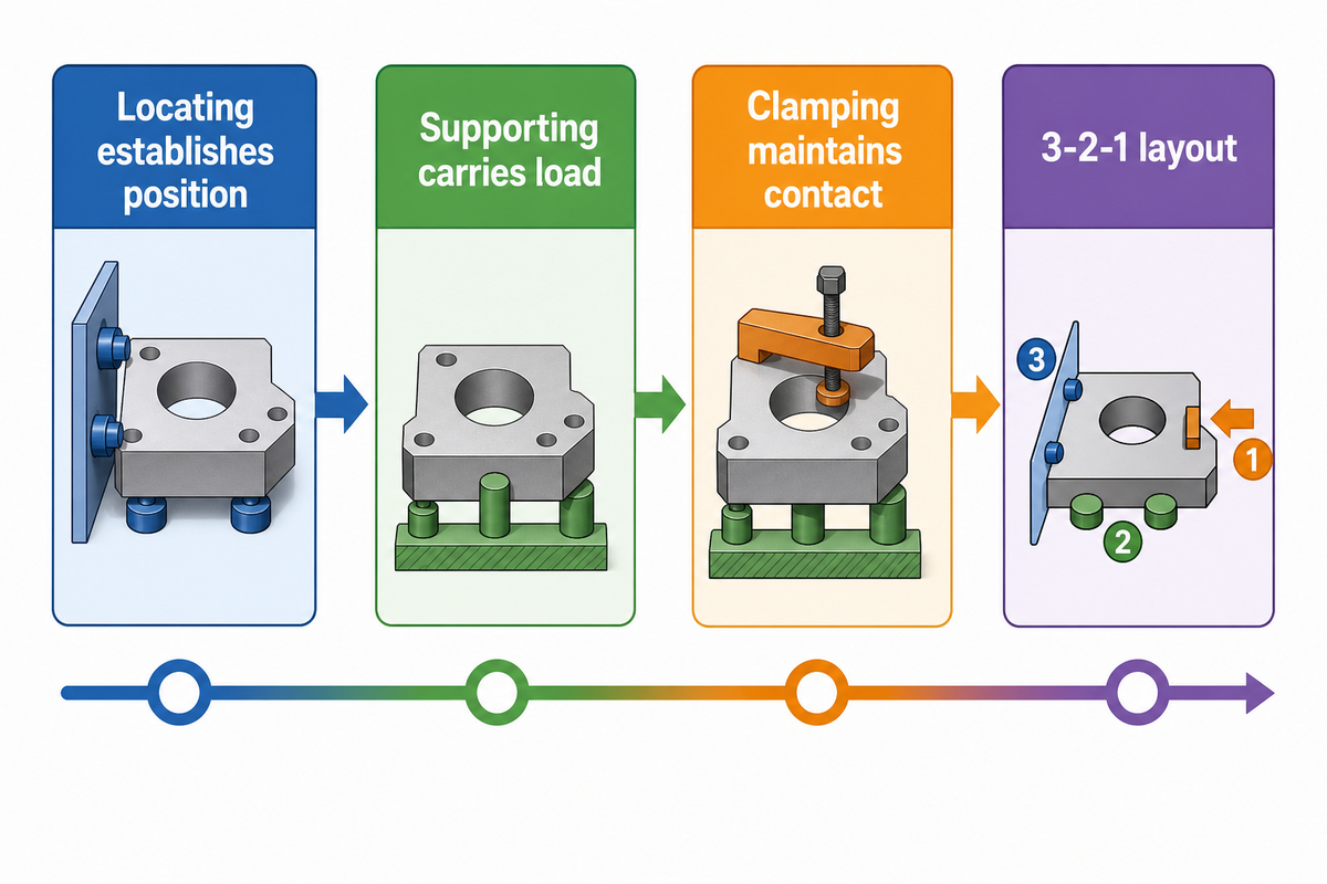
Locating establishes position; supporting carries load; clamping maintains contact against those defined surfaces. A practical 3-2-1 layout is a useful starting constraint map, but it is not a universal fixture recipe. Compliant or fragile parts may need broad bearing, floating supports, or a controlled way to avoid over-constraint. ISO 16090-1:2022 addresses machine-tool safety scope; it does not validate a particular fixture.
1. Drawing datum
Identify the functional surface or feature that the process must preserve.
Identify the functional surface or feature that the process must preserve.
2. Locator/support
Place contacts where they resist expected loads without creating an unknown constraint.
Place contacts where they resist expected loads without creating an unknown constraint.
3. Clamp direction
Drive the part toward the intended supports; do not make the clamp a second locating system.
Drive the part toward the intended supports; do not make the clamp a second locating system.
Then trace the machine reference, not just the fixture drawing. Burrs, chips, inconsistent blanks, thermal change, worn contact pads, and redundant contacts can make a nominally repeatable fixture seat differently. Before release, record the contact-cleaning method, seating check, locator condition, clamping sequence, and the inspection state in which accuracy is judged. The Fuji Technology Press study on thin-walled parts compared force and clamping sequence with simulation, strain measurement, and experiments; its useful lesson is methodological: measure the loaded state under stated conditions rather than borrow a universal force number.
Part-to-Proof Workholding Matrix, Compare 12+ Method Families
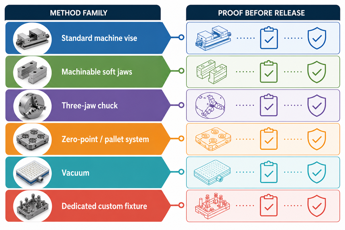
A method label conceals installed constraints. Use the matrix as a screening tool, then confirm the selected contact geometry and process state. “Best fit” suggests a starting position, not a definitive statement.
Teams use overlapping terms such as CNC workholding fixtures, CNC fixturing, and workholding devices. Treat each label as the start of a force-path and evidence review, not as proof that a method fits the part.
Translate Common Workholding Terms Into Engineering Checks
| Term group | Terms you may encounter | Engineering check |
|---|---|---|
| Milling | CNC milling, mill workholding solutions, CNC mill workholding, milling vise | Choose the right workholding from the machining plan, cutter path, datum transfer, and chip-clearance needs. |
| System language | workholding system, workholding device, workholding options, fixture systems, clamping system, solid workholding | Ask which elements locate, support, restrain, and verify the part; a product label alone does not define the installed system. |
| Access | 5-axis, multi-axis, point clamping, full access to the top, top of the workpiece | Confirm the space required for the holder, tool, probe, chips, and safe loading; low profile only helps when it allows access through the programmed envelope. |
| Turning | lathe, mill-turn, cylindrical parts, collet chucks | Check radial contact, axial location, runout, balance, speed boundary, and released-state geometry. |
| Production | high-volume, setup time, cycle times, many small parts, production processes | Compare changeover evidence, ability to reconfigure, production efficiency, and consistency across production runs before paying for automation. |
| Force and accuracy | cutting forces, holding force, part clamping, clamping parts, clamp workpieces | Show how contacts position and secure the part. To secure parts for machining accuracy and tight tolerances, verify part positioning, rigidity, deformation, and release behavior. |
| Vacuum and adhesive | vacuum workholding, vacuum systems, air pressure, double sided tape, super glue | Validate seal or bond area, material compatibility, cut-through risk, removal method, contamination, and surface quality. |
| Material and manual setup | raw material, cast iron, composite, manual machining, shim | Document material condition, bearing surface, cleanliness, operator method, and whether a shim changes the intended datum or support path. |
| Method | Best-fit part state | Contact / force idea | Main limitation | Proof before release |
|---|---|---|---|---|
| Standard machine vise | Prismatic, repeat jobs | Fixed jaw, movable jaw, parallels | Jaw lift, buried faces, limited side access | Jaw condition, seating, datum check, trial cut |
| Machinable soft jaws | Irregular or finished profiles | Formed contact around a known datum | Jaw wear and revision control | Jaw-bore record, revision, contact check |
| Step jaws and parallels | Simple stock and second ops | Raised datum with broad support | Limited shape and height range | Parallel height, burr removal, runout |
| Fixture plate with clamps | Flexible prismatic layouts | Pins/stops plus low-profile clamps | Many setup variables and collision checks | Hole pattern, clamp sweep, datum map |
| Three-jaw chuck | Round turning blanks | Self-centering radial grip | Repeatability and thin-wall distortion vary | Runout, jaw engagement, speed boundary |
| Four-jaw / independent chuck | Irregular or eccentric round work | Independent radial adjustment | Longer indication and operator variation | Indication record and balance check |
| Collet / expanding mandrel | Round, slender or finished bores | Distributed radial contact | Narrow size and surface limits | Fit, cleanliness, runout, release check |
| Modular / grid fixture | Mixed low-volume families | Reusable locators and clamps | Stack-up and changeover errors | Grid map, locator IDs, setup sheet |
| Zero-point / pallet system | Repeat pallets and multi-machine flow | Controlled interface and pull-down | Contamination, seating and interface ownership | Seated confirmation, orientation, recovery test |
| Dovetail / low-profile five-axis holder | Five-axis access, small footprint | Side grip with reduced obstruction | Limited engagement and collision envelope | Tool sweep, grip depth, stiffness check |
| Vacuum | Flat, sealed sheets or thin plates | Distributed pressure over a seal path | Leaks, porous stock, cut-through risk | Leak behavior, seal path, loss response |
| Magnetic | Suitable ferromagnetic parts | Distributed magnetic attraction | Material boundary and chip contamination | Material suitability, lift test, clean surface |
| Hydraulic / pneumatic powered | Repeat production and robot load | Controlled actuation toward locators | Pressure loss, guarding, fault behavior | Force/load basis, sensors, safe release |
| Adhesive / sacrificial carrier | Fragile or hard-to-grip geometry | Bond or carrier distributes contact | Debond, residue, process compatibility | Bond process, removal, surface inspection |
| Dedicated custom fixture | Stable family and defined sequence | Purpose-built datum and supports | Revision, storage and ownership | Controlled drawing, trial cut, acceptance owner |
The matrix is a public-data decision aid assembled from peer-reviewed workholding evidence, a university research summary, and applied trade context. It doesn’t rank one method for every part.
Match Workholding to Part Geometry and Process State
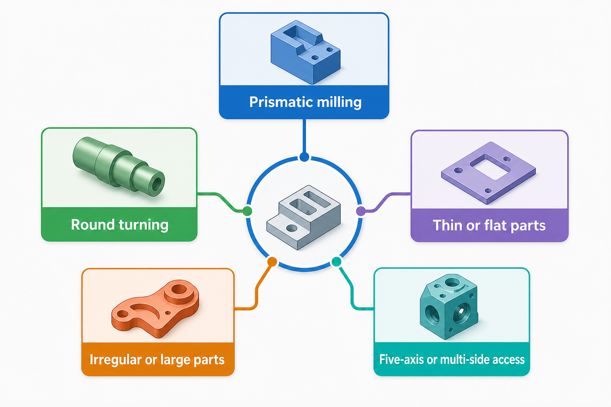
The raw blank, semi-finished part, and nearly finished part may have different contacts. Analyze the first concept using geometry and then find out how removing material affects stiffness on the mill or cnc machine.
- Prismatic milling: use a vise, jaw engagement, parallels, side stops, and broad support where the next operation needs a transferred datum. Keep the second-operation datum explicit.
- Round turning: compare the chuck, collet or mandrel contact with an axial stop, tailstock and steady support. Balance and speed limits are the responsibility of the process engineer and shouldn’t be placed on the method name.
- Thin or flat parts: spread support, limit local contact pressure, and check vacuum seal or magnetic-material boundaries. Take into account how to check the vacuum seal and inspect the part after it’s released.
- Irregular parts: use controlled nests, soft jaws or a dedicated carrier only if the contact surfaces and the loading sequence are defined.
- Five-axis parts: use low-profile contact only if the stiffness of the extension is checked, tool-holder collision is ruled out and probe access, chip removal, and recovery of the datum are checked after reorientation.
For thin-wall work, the useful question isn’t “what’s the strongest clamp?” but “what contact and sequence keep the part supported while material is removed?” A practical shop discussion also points to internal support, staged operations and temperature-aware inspection for large aluminium work; treat that as experience context, not a specification.
Workholding Failure-Transfer Map, Where a Setup Loses Accuracy
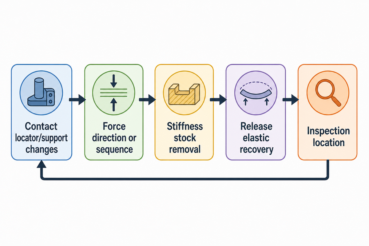
A fixture is able to load repeatedly and still produce bad released parts. Work your way backward and investigate every step in the entire process. This same principle applies to the case where the workholding solution is a vise on a machine table or a powered pallet:
Blank
variation, burr, chip
variation, burr, chip
→
Contact
locator/support changes
locator/support changes
→
Force
direction or sequence
direction or sequence
→
Stiffness
stock removal, vibration
stock removal, vibration
→
Release
elastic recovery
elastic recovery
→
Inspection
location, form, finish indicator
location, form, finish indicator
| Observed result | Possible transfer point | Next check |
|---|---|---|
| Dimension moves after unclamping | Elastic distortion or residual stress | Compare loaded and released-state measurements at stated temperature |
| Finish or chatter changes by location | Changing stiffness, tool access, or dynamic load | Review tool path, support span, contact condition, and vibration evidence |
| Part shifts between loads | Burr, chip, worn locator, or unclear clamp sequence | Clean-and-seat check, locator wear record, and sequence audit |
Published research on fixture states that locator and clamp arrays can cause issues with workpiece displacement and orientation. Thus, the release plan must provide contact geometry, perform a dynamic risk review and a trial cut, in addition to showing load repetition.
Tool, Probe, Chip, and Operator Access Are Workholding Inputs
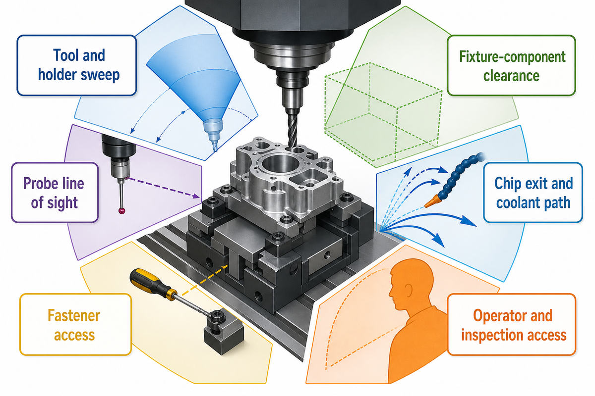
Secure contact is a geometrical requirement but not the only one. Before locking down the fixture geometry, perform an envelope checking review.
- tool and holder sweep through every programmed orientation;
- spindle, head, table, and fixture-component clearance;
- probe line of sight and repeatable probing access;
- chip exit, coolant path, clean-out and contamination control;
- fastener access, loading ergonomics, deburring and inspection access;
- safe removal of a finished thin-wall part without prying it out of shape.
Make the review visual. Overlay the fixture, stock envelope, tool-holder sweep and probe path on the same setup view, then check the worst operation rather than only the first one. Review the selected tool against the milling cutter guide before locking the access envelope. A clamp that clears a roughing tool may block a finishing holder or prevent a probe from seeing the recovered datum. Access also includes the person who loads and cleans the setup: awkward reach, hidden chips and a difficult release sequence create repeatability and safety problems that a static model won’t show.
For automated loading, NIST’s manufacturing-cell example shows contact sensing used to confirm fixture insertion, reinforcing that access and confirmation belong to the complete machine sequence.
When Standard, Modular, or Custom Workholding Makes Economic Sense
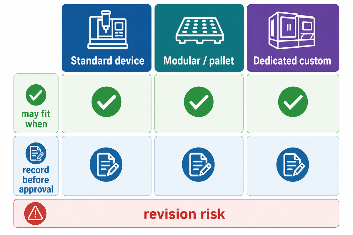
There’s no absolute “break-even” volume for a fixture. Assess the situation based on repeat volumes, setup labor, inspection effort, revision risk, storage, spare contacts, and cost of a flawed or distorted part. Sometimes the lowest buying price is the costliest option as it increases variation in every production batch.
| Option | May fit when… | Record before approval |
|---|---|---|
| Standard device | The part family and loading sequence are stable. | Setup minutes, indicating effort, scrap exposure, and access limits. |
| Modular / pallet | Several part variants share a controlled interface. | Changeover sheet, locator IDs, contamination and storage control. |
| Dedicated custom | A repeat family justifies a defined datum and proof plan. | Design/build cost, expected revisions, first-article work, and acceptance owner. |
Use the setup cost comparator to develop your own assumptions. The output won’t be a promised savings or payback period, but a scenario comparison, so keep that in mind.
In this analysis, also consider the risk of having to re-design. A dedicated nest may save indicating work, but it may become a restriction when a datum moves, a new tool direction is defined, or a 2nd material situation happens. A modular plate may take a bit more time to set for the first job, but it preserves an established interface for the variants of the job. Record who owns spare locators, jaw re-machining, storage, cleaning, and the decision to revise or retire the fixture.
Design Workholding for Changeover and Automation
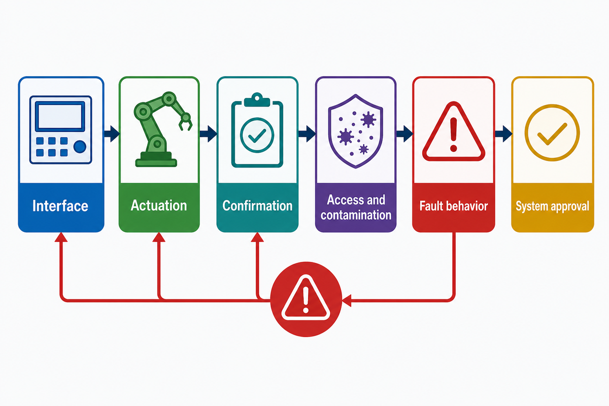
A powered clamp is one subsystem, not proof that an installed cell is ready for unattended production. NIST’s automated manufacturing-cell description combines pallet movement, an automatic vise, robot handling, buffers, structured-light inspection and tactile sensing; tactile sensing confirms fixture insertion in that example. The engineering lesson is to verify the complete sequence and recovery behavior.
- Interface: controlled orientation, repeatable mechanical contact and a documented datum reference.
- Actuation: Approved force/load and pressure limits by the responsible engineer.
- Confirmation: part-present, seated, clamped and unclamped signals appropriate to the risk.
- Access and Contamination: predictable robot access, chip management and clean contact surfaces.
- Fault behavior: loss-of-pressure or power state, alarm, recovery, manual override and safe release.
- System approval: guarding, lifecycle risk assessment, commissioning tests and operator instructions.
LANG publishes a product-specific example of a 96 mm grid, up to five modular units and up to 8.5 kN pull-down force for a stated QuickPoint configuration. Those values belong to that product and setup; they aren’t a universal CNC workholding threshold.
For an automated setup, stage the proof in the same order as the risk: dry-cycle the interface, confirm the part can only load in the designated orientation, test the seated and clamped signals with representative contamination controls, then confirm loss-of-pressure and recovery states. A supplier can manufacture a component that meets its drawing while the integrator still has to prove access, guarding, interlocks and the full machine sequence. Keep those signatures in the commissioning record. As a formatting example only, a worksheet might record a 96 mm interface, 8.5 kN product value, 0 bar loss state, 22 °C inspection condition, 15 min changeover observation and 120 rpm balance check; replace every placeholder with measured, configuration-specific evidence before approval.
Build the Fixture Readiness Evidence Pack
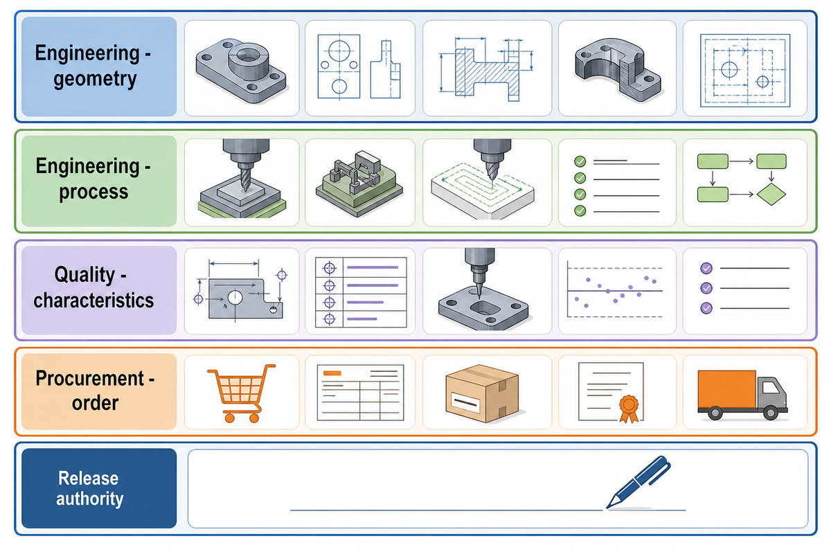
A three-dimensional model is a starting file, not an acceptance plan. Consider sending a controlled packet with four owners in mind:
| Owner | Fields to include |
|---|---|
| Engineering — geometry | Controlled 3D model, 2D drawing, revision relationship and functional datums. |
| Engineering — process | Machine references, raw/in-process states, operation sequence, tool access and cutting-load inputs. |
| Quality — characteristics | Critical characteristics, loaded and released inspection state and trial-cut dimensions. |
| Quality — records | Repeatability method, sampling, records, traceability and change control. |
| Procurement — order | Quantity, batch pattern, expected revisions, delivery and confidentiality. |
| Procurement — lifecycle | Commercial terms, storage, spare-contact expectations and revision ownership. |
| System owner — material | Material grade/condition, heat treatment, hardness, surface protection and cleanliness. |
| System owner — actuation | Actuation, sensors, guarding, fault behavior and installed-system acceptance. |
| Release authority | Named person who signs the evidence pack and approves production use. |
Publicly available information on fixture verification outlines separate fixture and machine verification stages. This includes locating and clamped stability and variable clamped forces over the duration of the machining process. Therefore, the practical handoff is a signed evidence pack with named acceptance ownership as opposed to an unqualified promise.
Formatting-only worksheet examples, not limits: write measured results as 0.00 mm, interface grid 96 mm, product-specific load 8.5 kN, loss state 0 bar, inspection condition 22 °C, changeover observation 15 min, balance check 120 rpm, leakage check 0.0 psi, repeatability result 0.00 mm, sample completion 100%, contact clearance 5 mm, force margin 1.0 kN, cycle observation 10 min, temperature delta 2 °C, pressure record 0.5 MPa, angular check 90°, secondary speed record 60 rpm, hold time 30 sec, thermal drift 1 °C, clean-out gap 2 mm, and signal delay 1 sec. Replace every placeholder with measured, configuration-specific evidence before approval.
Zhenling’s Build-to-Print Scope and Material Capability
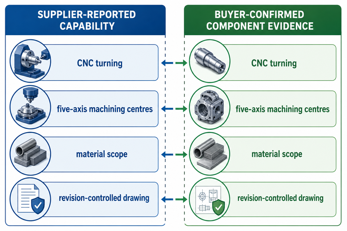
Shanghai Zhenling Hardware Co., Ltd. reported that the company started operations in 2006, running a factory in Jiashan, Zhejiang. Shanghai Zhenling Hardware Co., Ltd. states that it was established in 2006, operates a factory in Jiashan, Zhejiang, and supplies made-to-print non-standard metal components for pressure vessels, oil-and-gas separation, fluid control and related industrial uses. Shanghai Zhenling Hardware Co., Ltd. reports CNC turning, milling, grinding, boring, wire cutting, three-axis, four-axis, and imported five-axis machining centres, plate and rolling equipment, and welding capacity. These statements constitute supplier declared information for this guide. They don’t provide verification and aren’t independent assessments of a specific fixture or tolerance.
The supplied material scope includes bearing steel, carbon and alloy steels such as 20#, 45#, Q235A, Q345D, 12CrMoV, GCr15, 25CrMo and 42CrMo; stainless grades including 303, 304, 304L, 316, 316L and 321; nickel-based chemical-service alloys, C276, 904L and aluminium alloys. Ask for the grade, condition, traceability, heat treatment, hardness, inspection method and revision-controlled drawing for the actual component. A machine list or a reported CE/ASME credential does not by itself prove installed-system accuracy, operating limits, safety or certification of a workholding setup; the ISO 16090-1:2022 catalogue defines machine-tool safety scope rather than acceptance evidence for a specific fixture.
For a made-to-print fixture component, define Zhenling’s responsibility as follows: the component material and dimensions, the subassembly fit, or a broader design and validation scope. Place the responsibility boundary as defined above, prior to quotation acceptance.
Safety and Responsibility Boundaries
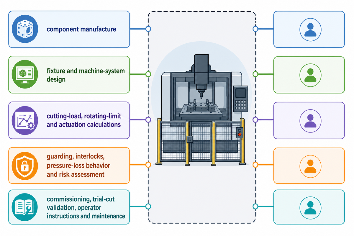
ISO 16090-1:2022 is a machine-tool safety scope reference for machining centres, milling machines and transfer machines; it is not evidence that a fixture, component or installed cell is safe. The broader project should name owners for:
- component manufacture, material and document scope;
- fixture and machine-system design;
- cutting-load, rotating-limit and actuation calculations;
- guarding, interlocks, pressure-loss behavior and risk assessment;
- commissioning, trial-cut validation, operator instructions and maintenance.
If the responsibility boundary is missing from a purchase order or project record, a component quote may be taken as approval of the complete machining system. Resolve this ambiguity prior to releasing the order for production.
For production release, add a simple change-control rule: each changed locator, jaw, seal, actuator, sensor, material or process condition, or machining sequence requires a new revision and assessment of whether previous evidenced trial cuts retain their validity. Maintenance is an essential element of accuracy. Define how contact surfaces are cleaned, how wear is checked, what contamination is unacceptable, and when a released-state inspection must be repeated.
Frequently Asked Questions
What is CNC workholding?
CNC workholding is the combined method of locating, supporting, restraining, and verifying a workpiece relative to the cutting tool. A vise, chuck, collet, fixture plate, vacuum table, or dedicated fixture is one element selected from geometry, force path, access, changeover, and inspection needs.
Is a stronger clamp always better?
No. More force can improve contact in one load case and distort a thin wall, close an access path or damage a surface in another. Define the supported datum, force direction, part stiffness, cutting loads and released-state inspection condition before selecting the clamp. The acceptance record should show what was measured, on which part state, with which contact condition, and who decided that the remaining deformation was acceptable.
Which method is best for thin-wall parts?
There’s no universal winner. Distributed support, soft jaws, vacuum, adhesive carriers, mandrels or a dedicated nest may each fit a different material and operation sequence. Compare contact geometry, local force, cut-through risk, heat, removal method and released-state measurement; run a trial cut when the consequence of distortion is high. A shop may also change the choice between roughing and finishing, because the remaining wall, contact surface and tool direction are no longer the same.
When should I use zero-point or powered workholding?
Use zero-point or powered workholding when repeat pallets, frequent changeover, or robot loading justify a controlled datum interface and verified actuation. The business case should include measured changeover time, production mix, unattended hours, and the cost of recovery from a misloaded pallet.
The engineering case should identify the locating interface, pull-down direction, allowable contamination, operating pressure or force range, and the machine states in which workpiece loading and release are permitted. Require orientation control, seating confirmation, independent clamped and unclamped signals, contamination checks, fault recovery, safe release, and a system risk assessment. Contamination buildup, loose chips or coolant, or an interrupted power supply during a supervised cycle should be tested to establish how the cell detects the state of the system and whether it returns to a known state. Power, in itself, isn’t a sign that the cell is operational; the setup should be approved for production only after the complete machine, fixture, controls, guarding, and system recovery have been verified according to the acceptance plan.
- Confirm pallet orientation before issuing any clamping command.
- Check seated, clamped, and unclamped signals independently.
- Challenge contamination at every controlled mechanical contact.
- Test pressure-loss and power-loss recovery under supervision.
- Document the safe release and manual override sequence.
- Assign approval for the complete installed machine cycle.
What should I send a workholding supplier?
Send the controlled model and drawing, functional datums, part states, material, operation sequence, access envelope, load inputs, inspection state, trial-cut requirements, quantity, and revision expectations. Use the GD&T symbols guide to check that the drawing communicates the intended controls. State whether the supplier owns component manufacture only or the wider fixture design and validation scope.
Ready to Turn the Force Path Into a Quote?
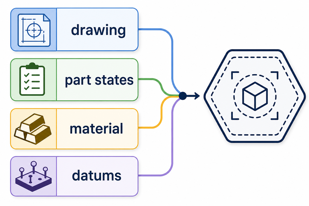
Provide the drawing, part states, material, datum, access restrictions, and a sequence of operations and the required evidence. The team from Shanghai Zhenling Hardware Co., Ltd. can analyze a made-to-print part, determine inputs required to submit a quote, and explain the dividing line for part machining, documentation, fixture design, and the validation of the installed system.
The fixture-verification research cited above separates fixturing and machining verification; use that distinction to define the project-specific evidence and acceptance owner in the request.
References & Sources
- ISO 16090-1:2022, Machine tools safety catalogue entry.
- Fuji Technology Press / International Journal of Automation Technology, workholding force, sequence and thin-wall deformation study.
- National Institute of Standards and Technology, automated manufacturing cell and tactile fixture-insertion sensing.
- Penn State, adhesive fixturing and method suitability by part, material and forces.
- Springer, machining-fixture verification and variable clamping-force abstract.
- LANG Technik, product-specific QuickPoint interface and pull-down example.
- Practical Machinist, thin-wall support and inspection experience discussion.
Supplier capability statements are marked as supplier-reported when independent verification is unavailable.
ABOUT ZHENLING
Custom machining from drawings and samples
Shanghai Zhenling Hardware Co., Ltd. was established in 2006. Its Jiashan, Zhejiang factory covers an 8,000 m² site with a 6,000 m² workshop for custom machined metal parts.
The team works from drawings and samples for applications including pressure vessels, oil-gas separation, and fluid control. Material experience includes carbon, alloy, and stainless steels as well as special alloys.
- 3-, 4-, and 5-axis CNC machining
- Grinding, wire cutting, and welding
- Domestic and export divisions
CONTACT PROFILE
Company details
- NAME
- Shanghai Zhenling Hardware Co., Ltd.
- ESTABLISHED
- 2006
- LOCATION
- Jiashan, Zhejiang, China
- FOCUS
- Custom machined metal parts from drawings and samples
- CAPABILITIES
- 3/4/5-axis CNC machining, grinding, wire cutting, and welding
- CONTACT
- Share the drawing, material, quantity, and critical requirements.