Speeds and Feeds Calculator for CNC Milling and Turning

The Speeds and Feeds Calculator is a planning tool that uses cutting speed, tool diameter, flute count, and chip load to determine RPM and feed rate. The values can assist in making a plan for cutting. However, the final parameters still need to be determined by the user based on conditions such as the workpiece material and tool condition, tool holder and work- and tool-engagement, coolant, and the degree of automation and control of the machining center. Safe first-cut parameters should always be set by a human using the exact tool, material condition, machine, controller mode, holder, workholding, engagement, coolant, and inspection plan.
Updated: September 2026
Bottom line
Calculate RPM and feed, then test the answer against five gates: qualified source data, controller and machine limits, cutting geometry, setup stability, and controlled first-cut evidence.
Quick answer
- RPM links cutting speed to the diameter actually cutting.
- Milling feed rate equals RPM × effective teeth × chip load per tooth.
- Turning and drilling may use feed per revolution; tapping feed is locked to thread lead.
- Catalog values are starting inputs, not proof that a setup is stable.
- Record units and assumptions before sending a number to CAM, production, or a supplier.
| Quantity | Inch form | Metric form | Input warning |
|---|---|---|---|
| Spindle speed | RPM = 12 × SFM ÷ (π × D in) | RPM = 1000 × m/min ÷ (π × D mm) | Use effective cutting diameter where required. |
| Milling feed | IPM = RPM × teeth × IPT | mm/min = RPM × teeth × mm/tooth | Count teeth that effectively cut, not merely teeth listed. |
| Feed per revolution | IPR = IPM ÷ RPM | mm/rev = mm/min ÷ RPM | Confirm controller feed mode before entry. |
| Tapping feed | Single-start: IPM = RPM ÷ TPI | Single-start: mm/min = RPM × pitch | Multi-start threads use lead; rigid tapping requires synchronization. |
Calculator and Output Definitions
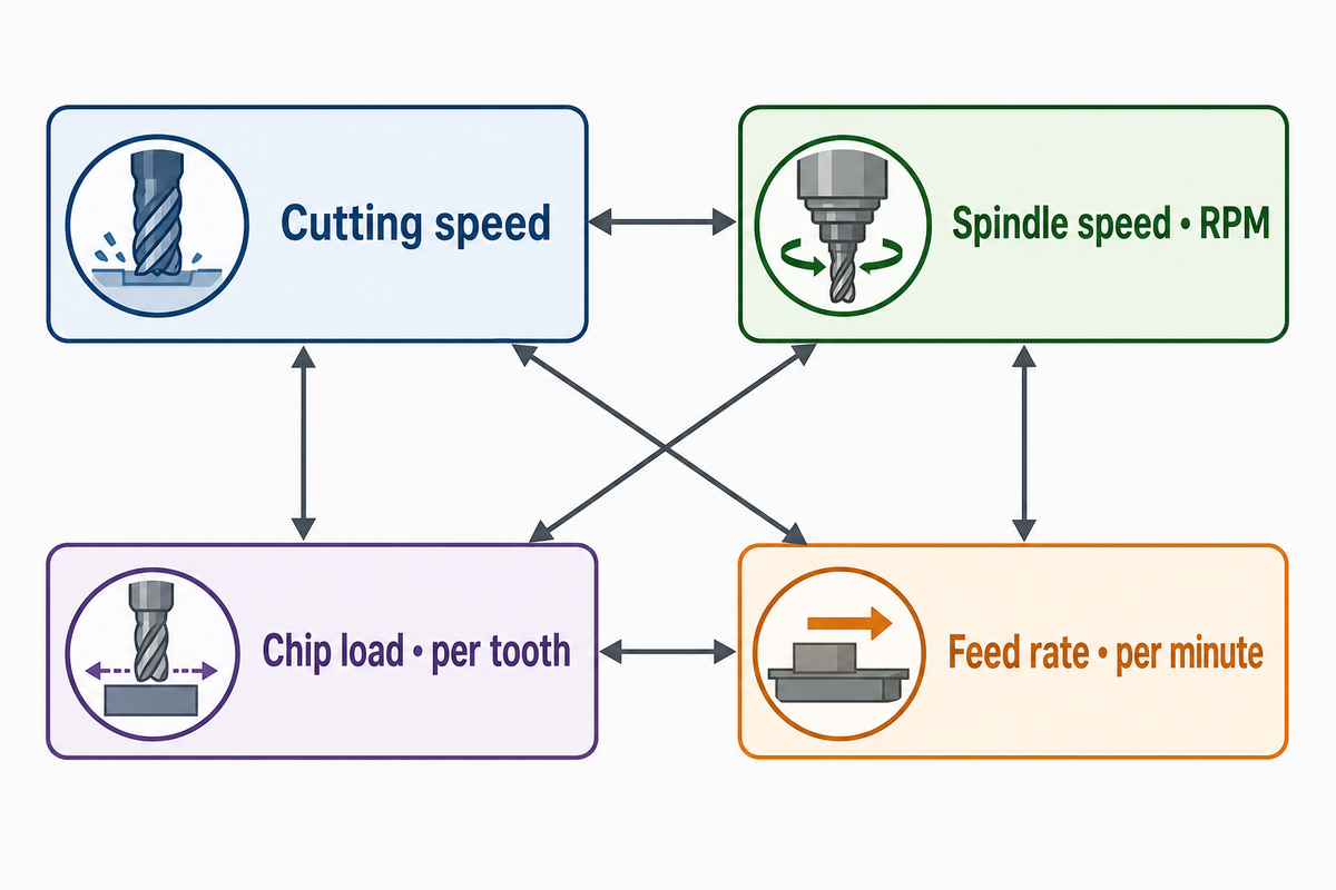
A good calculator provides the user with the ability to see all constants, units, formulas, and rounded answers. Used as a cutting speed calculator or spindle speed calculator, it gives an approximate RPM value from cutting speed and diameter. As a feed rate calculator, it determines approximate feed values per minute from RPM, the number of effective flutes, and chip load. The answers provided don’t necessarily mean that the calculator is validating the input or giving permission to run the tool. The answers should always be cross checked against the source.
How fast the cutting edge moves, described in terms of its diameter, is surface speed. Inch practice refers to surface speed in terms of surface feet per minute (SFM); in metric practice, surface speed is expressed in terms of meters per minute (m/min). The revolutions per minute (RPM) of the spindle is referred to as spindle speed. The distance a tool advances per tooth is chip load, while feed rate is the resulting distance the workpiece advances per minute. The rate at which feed is accomplished is defined as feed rate.
The familiar conversion is geometry: RPM = 12 × SFM ÷ (π × diameter in inches), or RPM = 1000 × cutting speed in m/min ÷ (π × diameter in millimeters). The milling feed is RPM × number of effective cutting teeth × feed per tooth. The feed is expressed in mm/rev for turning and drilling operations, and may be directly programmed.
Rounded outputs can look more certain than their inputs. “Stainless steel” doesn’t disclose alloy, heat treatment, hardness, scale, or work-hardened skin. Nominal 12 mm end-mill diameter doesn’t disclose runout, stickout, geometry, coating, or wear. Check machinability reference data and the toolmaker recommendation before choosing starting values.
Four Inputs Behind RPM and Feed Rate
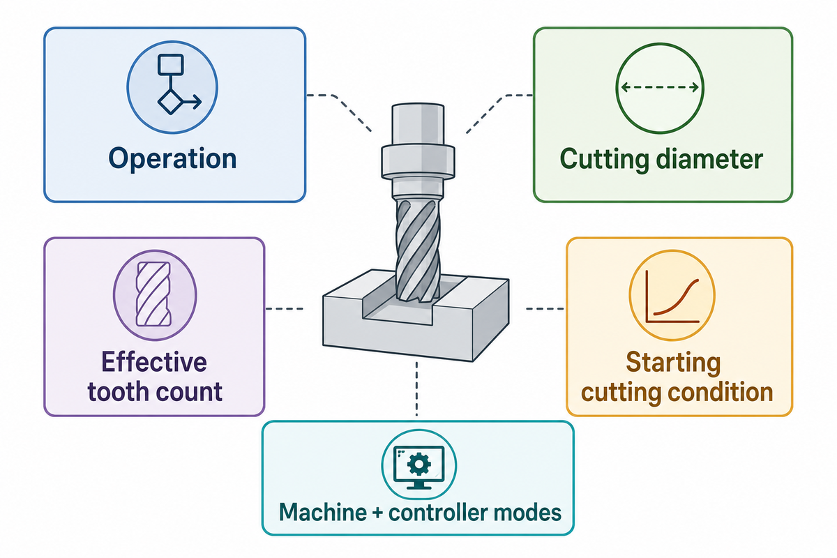
The key to performing a correct analysis lies in the identification of four criteria: the operation, the cutting diameter, the effective tooth count, and the starting cutting condition for the material-tool combination in question. Each of these factors has an associated limit. Knowing these allows us to determine from where in the analysis a limiting assumption has been made. A clean-looking formula shouldn’t lull us into believing that no assumptions have been made.
1. Operation and controller intent
Name the operation and use the appropriate formula for it. Different operations such as milling, drilling, turning, tapping, and thread milling are NOT controlled by the same feed model. Some CNC controls support feedback and synchronization. Mistakes in controller mode selection can turn correct arithmetic into a large motion error.
2. Diameter at the cutting contact
Only nominal diameter is appropriate for straight peripheral cuts for which contact geometry determines the toolpath. Ball-nose contact near the tool center has a smaller effective diameter. Toolpaths generated using constant surface speed define RPM from a cutting diameter that changes continuously over time. Toolpath along an arc is also defined by a changing diameter.
3. Effective teeth, runout, and flute condition
Flute count assumes even chip distribution, but many factors can result in built-up edge, uneven thickness in chips, and/or excessive load on one tooth. These include tool run-out, variation in insert height, edge chipping, built-up edge and holder contamination. Thus, the actual chip thickness loaded on each tooth of a four-flute cutter may vary from the calculated average.
4. Qualified cutting speed and chip load
Start with the toolmaker’s data for the specific cutter, tool material, grade, coating, workpiece material, hardness, operation, and engagement. Then check whether the recommendation assumes a machine, coolant strategy, holder, or depth of cut that differs from the real job. Verified hardness test context can be as important as the alloy name when stock condition is uncertain.
Record
- Operation and toolpath type
- Units beside every input
- Toolmaker source and tool code
- Material grade, condition, and hardness
- Machine and controller modes
Do not assume
- Nominal diameter always equals contact diameter
- Every flute carries equal load
- A chart covers every operation
- Displayed decimals equal process certainty
- A previous job transfers unchanged
Worked Milling Example in Inch and Metric Units
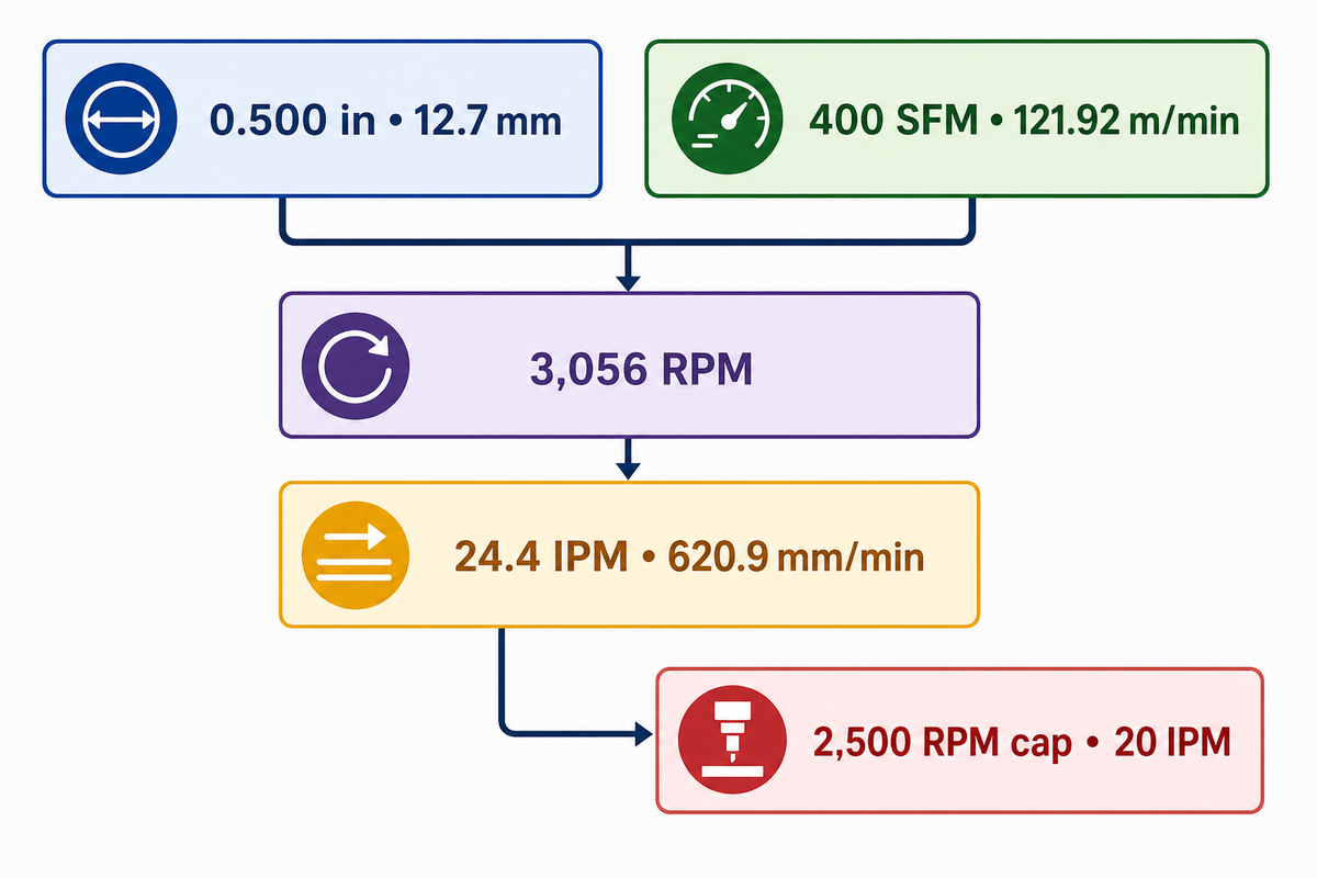
Using the standard spindle-speed and milling-feed relationships in both metric and imperial systems is a check against calculation mistakes in conversions. For a 0.500-inch (12.7 mm), four-flute cutter at 400 SFM (121.92 m/min), and 0.002 inch (0.0508 mm) per tooth, both calculations should result in 3,056 RPM and the same feed rate.
Inch calculation
RPM = (400 × 12) ÷ (π x 0.500) = 3,055.77 RPM, rounded to 3,056 RPM. Feed rate is 3,055.77 × 4 × 0.002 = 24.446 inches per minute, generally shown as 24.4 IPM.
Metric cross-check
RPM = (1000 × 121.92) ÷ (π × 12.7) = 3,055.77 RPM. Feed rate is 3,055.77 × 4 × 0.0508 = 620.9 mm/min. Converting 24.446 IPM by 25.4 gives the same 620.9 mm/min, apart from display rounding.
Consistency of units and numerals is all the arithmetic check ensures. It can’t prove that 400 SFM or 0.002 IPT is acceptable for the workpiece, cutting tool, coolant, holder, spindle, or setup. A 0.002 IPT value is not a universal standard; the usable value depends on the tool, workpiece, engagement, and cutting speed. If the machine spindle is limited to 2,500 RPM, preserving the stated four-flute value of 0.002 IPT requires a feed rate of 20 IPM. A reduction in spindle speed requires a corresponding reduction in feed rate to preserve chip load. Keeping 24.4 IPM after reducing RPM would raise programmed chip load to about 0.00244 inch per tooth.
Keep a second verification vector for calculator testing: a 10 mm cutter at 100 m/min returns 3,183 RPM. With 4 teeth at 0.05 mm/tooth, feed is 636.6 mm/min. If the spindle is capped at 3,000 RPM, matched feed becomes 600 mm/min. A different result signals a unit, formula, or rounding error before any machine trial. The vector doesn’t approve an 8 mm axial depth or 2 mm radial width; engagement still needs its own evidence.
Calculation check
When RPM changes, recalculate feed if the intent is to preserve chip load. A feed override or spindle clamp changes the relationship unless the control couples them.
Milling, Turning, Drilling, and Tapping Boundaries
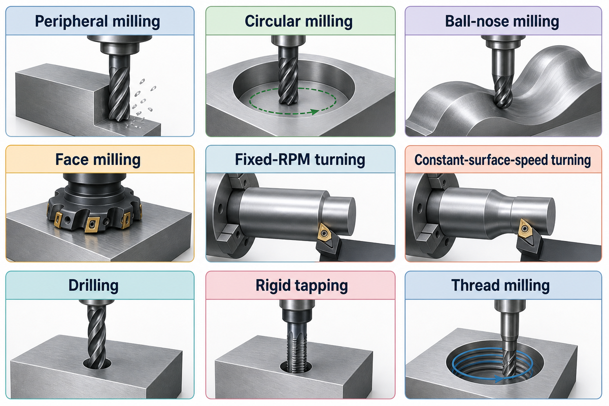
The Operation Boundary Matrix separates formula families and controller assumptions prior to the machine. Use this to identify the diameter, feed expression, and mode for different milling operations and other machine processes. This matrix is a reviewing tool and shouldn’t be used to replace the data provided by the toolmaker. This matrix doesn’t replace the machining manual.
Operation Boundary Matrix
See table below for where each operation begins and ends calculation and what verification is required.
| Operation | Diameter basis | Feed basis | Control or geometry check | Limitations / Not suitable for |
|---|---|---|---|---|
| Straight peripheral milling | Nominal cutter diameter | Feed per tooth × effective teeth × RPM | Verify radial and axial engagement | Does not correct chip thinning or runout automatically |
| Small-radius circular milling | Cutter diameter plus path relationship | Tool-center feed, not merely contour feed | Check internal versus external arc | Straight-line feed may distort edge speed around tight arcs |
| Ball-nose milling | Effective contact diameter | Feed per tooth with contact geometry | Check tilt, stepdown, and contact point | Nominal diameter is unsuitable near the tool center |
| Face milling | Cutter sweep diameter | Feed per tooth × engaged teeth logic | Check lead angle and entry strategy | Solid-end-mill data should not be transferred blindly |
| Fixed-RPM turning | Work diameter at the cut | Usually feed per revolution | Confirm G-code mode and units | Surface speed changes as diameter changes |
| Constant-surface-speed turning | Live work diameter | Feed per revolution with changing RPM | Set and verify maximum-RPM clamp | Unsafe to use without chuck, workholding, and RPM limits |
| Drilling | Drill diameter | Feed per revolution or linear feed | Verify peck, depth, coolant, and chip exit | Milling chip-load tables do not define drill feed |
| Rigid tapping | Tap diameter for speed selection | RPM × thread lead | Confirm synchronization, starts, pitch, and units | Pitch alone is insufficient for multi-start threads |
| Thread milling | Cutter diameter plus helical path | Tool-center feed with path compensation | Check pitch, interpolation, and internal/external path | A tapping feed formula does not apply |
In constant-surface-speed turning, RPM decreases with increasing diameter. The maximum RPM clamp should be determined by chuck rating, workpiece and workholding balance, system stiffness, and machine tool limits. When considering a turning operation, the type of cutter, the lead angle, and the geometry of the flutes should be analyzed. Review the effects of chip space and pick up the values for cutter engagements in a milling cutter selection review.
Chip Thinning and Effective Diameter Corrections
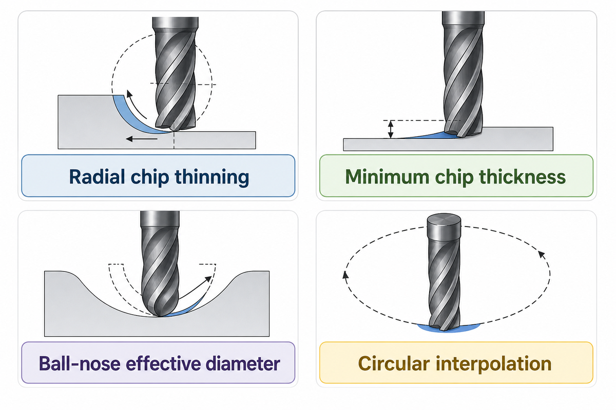
Radial chip thinning and ball-nose geometry at the cutting edge can make programmed chip load differ from the chip formed at the cutting edge. Make the correction only when supported by toolmaker’s or other verifiable geometries. Less than 50% radial engagement marks a chip thinning condition, not a universal boundary between cutting and rubbing.
In peripheral milling a tooth engages less material, and, as a result, the chip formed may be less than the chip programmed to be formed. In such cases, to ensure the chip formed is within limits, programmed feed may have to be increased.
Minimum chip thickness is a different issue. Factors such as the behavior of the material, the speed and condition of the cut, lubrication, tool wear and runout, can cause the edge to shear or plough. An edge that’s shearing shouldn’t be regarded as rubbing, just because it has less than 50% of the tool engaged. Nor should a chip-thinning factor be regarded as allowing an edge to plough.
Cutting with a ball-nose tool produces lower cutting speed near the center; chip formation and the cut depend on how the tool engages the stock, not merely whether engagement is complete. How much stock is engaged, plus tool tilt, stepdown, stepover, and position, determines the effective diameter.
Circular Interpolation makes a few further corrections. Feed and speed controls may differ during a contour operation. Internal arcs can require the tool center to travel a smaller radius; external arcs create the opposite relationship. Use the method available in your CAM/controller to achieve the path required. Tool-center feed may change during a contour operation, so capture both the contour intent and posted result during setup.
The 5-Gate Calculated-to-Cut Validation Ladder
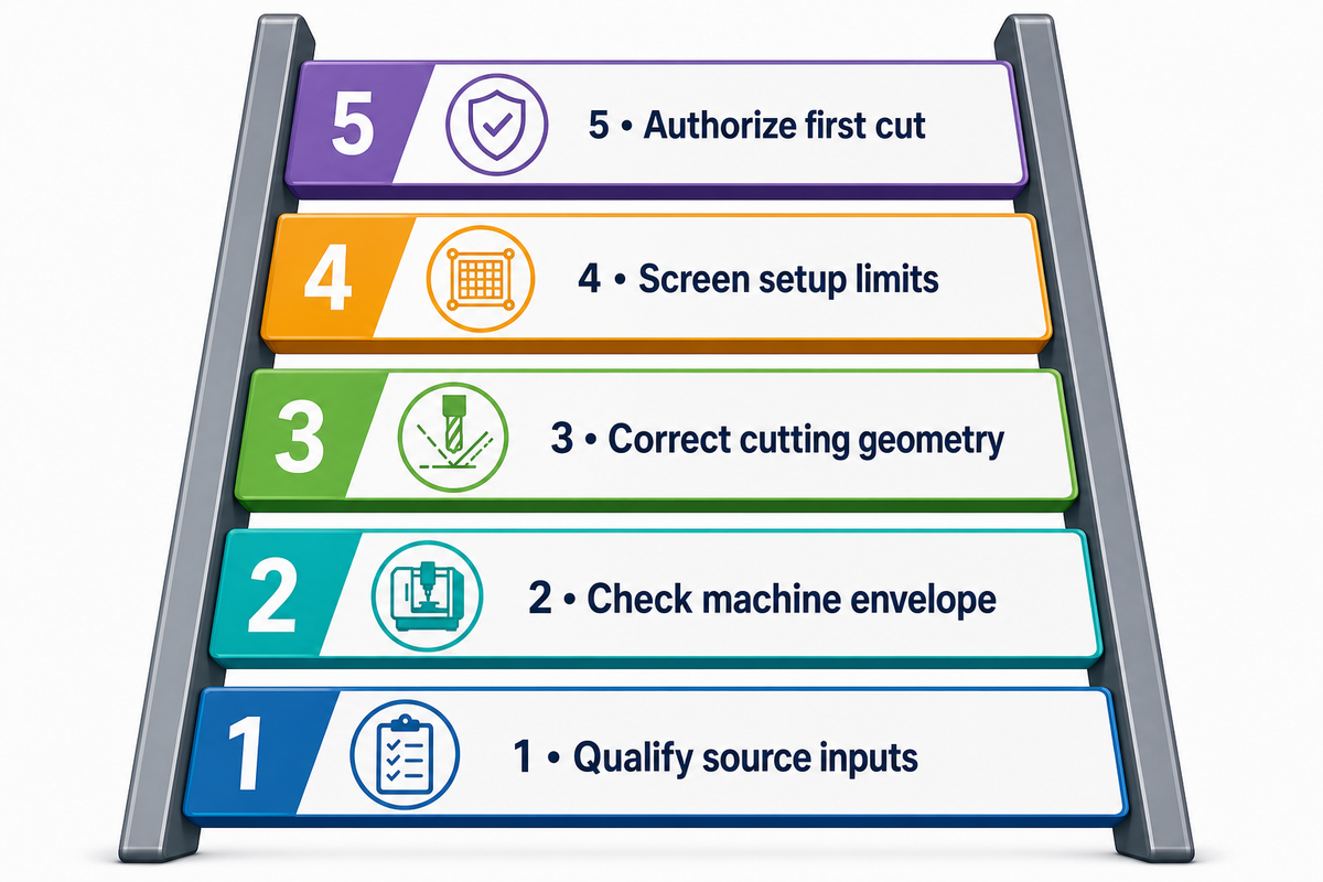
The 5-Gate Calculated-to-Cut Validation Ladder turns a numerical answer into a controlled starting point. One gate doesn’t remove the need to evaluate the next. Several machine-tool and control-system checks, workpiece and setup checks, and checks of the tool and cutting conditions must be completed before releasing parameters for repeat production.
5-Gate Calculated-to-Cut Validation Ladder
A five-point checklist is provided to assess if the output of a calculator may be safely used to enable a first machining operation.
- Qualify the source inputs: match tool code, grade, coating, material grade and condition, hardness range, operation, engagement, and coolant assumption to the toolmaker data.
- Check the control and machine envelope: verify feed mode, speed mode, unit state, maximum RPM, spindle power and torque, axis feed and acceleration, and tapping or interpolation capability.
- Correct the cutting geometry: review effective diameter, radial chip thinning, engaged teeth, runout, entry, circular path, lead angle, and flute or insert condition.
- Screen dynamic setup limits: assess axial depth, tool and holder overhang, spindle-holder-tool interfaces, workpiece stiffness, fixture support, coolant delivery, and chip evacuation.
- Authorize a controlled first cut: set a conservative, documented start; observe load, sound, chips, temperature, finish, size, and tool condition; change one variable at a time and preserve the evidence.
Factors influencing stability include cutter axial depth, overhang, holder and spindle condition, fixture and workpiece stiffness, and the geometry of the stock and part. Tool stickout of 40 mm versus 60 mm can lead to different conclusions. Even moving from 40 mm to 60 mm tool stickout can invalidate a prior result; a short-tool trial doesn’t transfer automatically to a thin-wall, long-reach cut.
Standards must be kept within their stated scope. ISO 3685 concerns tool-life testing with single-point turning tools, while ISO 8688-1 addresses tool-life testing in face milling. Neither standard certifies this calculator or validates the five-gate ladder. Their narrow scopes illustrate why a test method should not be generalized to a different operation or setup.
Safeguards, doors, interlocks, operating procedures, and employer controls remain in force during trials.
“The point of operation of machines whose operation exposes an employee to injury, shall be guarded.”
Use the machine manufacturer’s instructions and site safety process for setup and proving. Personal protection means keeping personnel clear of the hazard zone; guarding must never be bypassed. Guards should never be bypassed.
Troubleshoot Chatter, Heat, Rubbing, and Poor Finish
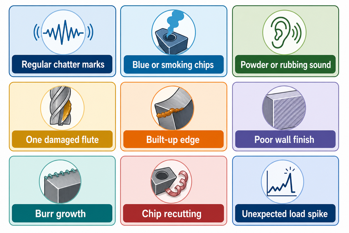
When there’s a condition requiring adjustment or correction, the controlling variable should be identified and changed while maintaining the relationship of the other variables of the chip load. Sound alone shouldn’t be used for diagnosis. Other items such as spindle loading, chip form, temperature, workpiece condition and edge, dimensional results, surface condition, and the tools used should be evaluated.
| Observed signal | Check first | Controlled response | Evidence to retain | Limitations / Not suitable for |
|---|---|---|---|---|
| Regular chatter marks | Overhang, fixture support, engagement, RPM band | Shorten or stiffen first; test one speed change | Sound, load, finish pattern, exact RPM | Feed reduction alone can worsen rubbing |
| Blue or smoking chips | Cutting speed, coolant delivery, edge wear | Stop and inspect; correct delivery or reduce supported speed | Chip color, edge photo, temperature method | Chip color is material- and process-dependent |
| Powder or rubbing sound | Actual chip thickness, runout, worn edge | Restore a supported chip thickness or replace tool | Chip sample, runout reading, edge condition | Do not raise feed without load and stability checks |
| One damaged flute | Runout, insert seating, holder cleanliness | Correct mechanical cause before recalculating | Flute-by-flute inspection and runout | Average chip load hides unequal tooth loading |
| Built-up edge | Material, edge geometry, speed, lubrication | Use toolmaker guidance; inspect coolant concentration | Edge photo, coolant record, finish | No universal speed adjustment fits all alloys |
| Poor wall finish | Deflection, radial stock, toolpath, runout | Separate roughing and finishing stock; improve support | Surface direction, size, stock allowance | A feed change cannot correct loose workholding |
| Burr growth | Edge wear, exit direction, material condition | Inspect tool; revise exit strategy if supported | Burr location, tool life, material lot | Feed is only one possible cause |
| Chip recutting | Flute capacity, air or coolant aim, pocket depth | Improve evacuation; reduce depth if required | Chip packing location and delivery setup | More coolant volume may not reach the cutting zone |
| Unexpected load spike | Stock variation, corner engagement, mode, unit state | Stop, locate event, verify posted path and inputs | Load trace, block number, stock map | Do not mask a path error with an override |
Check workholding rigidity first. Adjust tuning parameters second. If the symptom changes between nominally identical parts, inspect stock condition, tool seating, runout, insert indexing, coolant aim, and fixture contact before treating the calculator as the source of variation.
Build a Calculation Handoff for CAM or RFQ Review
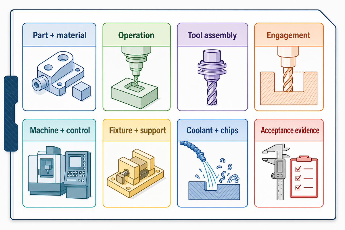
The process calculation handoff evidence packet should be sent with any assumptions made. This will allow the receiving party, i.e. machinist or quality personnel, to evaluate the process and make modifications if needed. The evidence packet, along with the assumed process, will allow an accurate quote to be given.
Calculation Handoff Evidence Pack
Concise data records should link calculated values to the job, source, setup, and acceptance evidence.
CAM and RFQ checklist: copy these fields into the handoff.
| Parameter | Required detail | Why it matters | How to verify |
|---|---|---|---|
| Part and material | Drawing revision, grade, condition, hardness, stock state | Controls cutting-data relevance | Drawing, certificate, hardness result |
| Operation | Feature, rough/finish intent, toolpath radius, entry and exit | Selects formula and path corrections | CAM screenshot and setup sheet |
| Tool assembly | Tool code, grade, geometry, holder, stickout, measured runout | Defines contact and load sharing | Tool list and presetter/runout record |
| Engagement | Axial depth, radial width, effective diameter, engaged teeth | Changes chip thickness and stability | CAM analysis and simulation |
| Machine and control | Machine ID, unit state, feed/speed modes, RPM clamp, axis limits | Prevents mode and envelope errors | Machine manual and posted program |
| Fixture and support | Clamping, datum, part extension, thin walls, support sequence | Bounds deflection and vibration | Setup photo and fixture plan |
| Coolant and chips | Type, concentration, delivery, filtration, evacuation path | Affects heat, lubrication, and recutting | Coolant record and trial observation |
| Acceptance evidence | Tolerance, finish, inspection method, sample plan, tool-life stop | Defines what a successful cut means | Inspection plan and signed trial record |
The machinist needs a means to control the start and stop of the process. The CAM programmer requires a specification for path and motion. Quality requires specification for revision and acceptance. The buyer requires specification for inspection and the condition of the material. The plant manager requires a demonstration of process capability and repeatability for the process and equipment.
Based on public site information and the company profile supplied for this page, Shanghai Zhenling Hardware Co., Ltd. works with custom machined components across carbon and alloy steels, stainless steels including 904L, nickel-based alloys including C276, and aluminum alloys. The company states that its equipment includes 3-axis, 4-axis, and 5-axis machining centers. Useful supplier review starts with the exact drawing, material specification and condition, quantity, tolerance, surface finish, and inspection requirement, not a calculator screenshot. Reviewers shouldn’t rely on calculator screenshots for requirements.
For a drawing-based machining review, complete the fields on the contact page or use the below RFQ form and send. Submit the machining context needed for a useful review and feedback. Use the review to identify the arithmetic inputs and the machine-specific process decisions.
Frequently Asked Questions
The remaining questions are focused on choice of formula, level of input, and where to define process limits. The answers do not provide assurance that the process has been validated.
How do you calculate speeds and feeds?
Answer
Choose a cutting speed from qualified toolmaker data, then calculate RPM from surface speed and cutting diameter. In inch units, RPM = 12 × SFM ÷ (π × diameter in inches). In metric units, RPM = 1000 × m/min ÷ (π × diameter in millimeters). For milling, multiply RPM by effective teeth and chip load per tooth. For turning or drilling, confirm whether the control expects feed per revolution or feed per minute.
What is the best calculator for calculating speeds and feeds?
Answer
The best feeds and speeds calculator for a job exposes its formulas, units, source assumptions, operation, and machine limits. Toolmaker calculators can help when tied to the exact cutting tool family and material group. General calculators suit transparent arithmetic and unit checks. Neither type should hide effective diameter, chip thinning, controller modes, RPM clamps, or the need for a controlled first cut. Prefer the one that lets another reviewer reproduce every input and rounded output.
What is the formula for calculating tapping feeds and speeds?
Answer
For rigid tapping, linear feed equals RPM multiplied by thread lead. For a single-start inch thread, IPM equals RPM divided by threads per inch; for a single-start metric thread, mm/min equals RPM multiplied by pitch. Multi-start threads use lead, which equals pitch multiplied by the number of starts. Choose RPM from tap-maker data, then confirm synchronization, units, holder, hole depth, and chip strategy.
How do you calculate SFM for milling?
Answer
SFM equals π × cutter diameter in inches × RPM ÷ 12. For example, a 0.500-inch cutter at 3,056 RPM is about 400 SFM. Use effective contact diameter instead of nominal diameter when ball-nose or other contact geometry requires it. Keep diameter units in inches.
Do face mills and solid end mills use the same speeds and feeds?
Answer
No single value should be transferred automatically. Both use cutting speed and feed-per-tooth concepts, but their insert or flute geometry, lead angle, effective engagement, edge preparation, tooth count, entry path, chip space, cutter diameter, and typical depths differ. Face-mill data may assume a specific insert grade, body, entry angle, and width of cut, while solid-end-mill data may depend on flute length, helix, core, and radial engagement. Machine power and low-RPM torque can also constrain the two tools differently. Start with toolmaker data for the exact assembly and material. Then apply machine, path, workholding, coolant, runout, and first-cut checks for that operation. Record which source supplied each input so a later reviewer doesn’t blend the two application ranges.
Why does my calculated speed feel too conservative or too aggressive?
Answer
The calculator may be correct while an input or boundary is wrong. Check material grade and hardness, tool code, effective diameter, radial and axial engagement, runout, wear, overhang, holder, machine torque, controller mode, coolant, chip evacuation, and workholding. Compare the result with the exact toolmaker application range. Change one documented variable during a controlled trial instead of judging the value by sound alone, and record the result before another adjustment.
Related CNC Machining Guides
- CNC process controls and fundamentals
- Machinability reference data by material
- Metal hardness and test context
- Types of milling cutters
- CNC workholding and rigidity
References & Sources
- University of Florida: Speeds and Feeds
- Open Oregon Educational Resources: Unit Two, Cutting Speed
- MIT Center for Bits and Atoms: Fablab Speed and Feeds Calculator
- U.S. Occupational Safety and Health Administration: 29 CFR 1910.212
- ISO 3685: Tool-life testing with single-point turning tools
- ISO 8688-1: Tool-life testing in face milling
Use boundary: The formulas and examples are intended to illustrate methods for calculating part features. The final decisions for process and procedural limits as well as the authorization for cutting part features are determined by the machine tool builders and operators in conjunction with the employer’s safety process and the control of the machine tools.