CNC Workholding Explained with Diagrams and Examples
Build-to-print workholding components
CNC workholding begins with a controlled datum and ends with a workpiece that stays located through the cutting cycle. We manufacture made-to-print fixture plates, jaws, locators, supports, clamps, pallets and related custom-machined parts from your approved drawing package.
- Written quotation confirms scope and timing after drawing review
- Written quotation confirms quantity and payment after drawing review
- Written quotation confirms shipping and document scope after drawing review
- Include an available 3D model and controlled 2D drawing
Quote response
Confirmed in the written quotation after drawing reviewPrototype schedule
Confirmed in the written quotation after drawing reviewMinimum order
Quantity confirmed in the written quotation after drawing reviewFiles accepted
Include an available model and controlled drawing with the RFQDrawing protection
Confidentiality requirements confirmed in writing before detailed file exchangeOrder records
Required document scope confirmed in written quotationCNC Workholding Selection and Component Scope
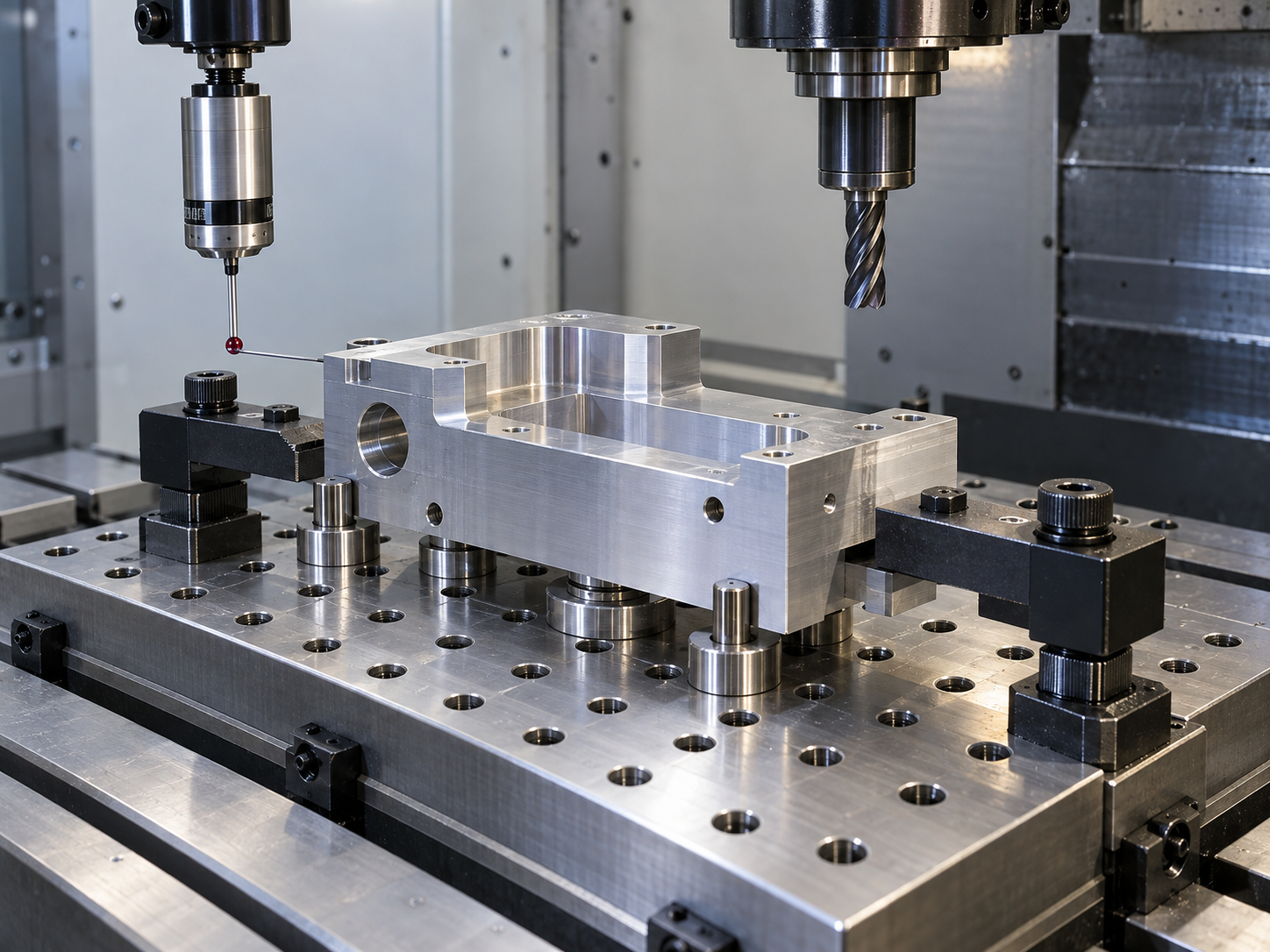
The best CNC workholding setup is selected by part geometry, datum scheme, cutting-force direction, tool access, material response and production volume. Depending on the constraints, a vise, chuck, collet, vacuum table or dedicated fixture may hold the part in different ways.
Terms buyers often mix up
- CNC workholding methods describe how a part is located, supported and restrained.
- CNC workholding solutions combine the fixturing method with the machine interface, operation plan and acceptance controls.
- CNC workholding fixtures are the physical devices or assemblies that carry those decisions.
- A jig guides a tool as well as holding the part; a machining fixture locates and restrains the part without guiding the cutter.
Geometry-to-Holding Board
The Geometry-to-Holding Board compares part form, operation access and contact limits before a buyer commits to a fixture concept. Use it to frame the RFQ, then confirm the choice against the actual machine, toolpaths and controlled drawing.
Five assumptions to test before an RFQ
- The second operation loses the first-operation datum when its locating feature is removed or cannot be reached.
- More parts per cycle do not necessarily reduce unit cost when loading, reach and chip clearance become harder.
- Manual clamp consistency can drift with access and operator position; powered clamping adds control and safety obligations.
- Higher clamp force is not always safer because unsupported contact can deform a compliant wall.
- A dedicated fixture is not always the right call when a standard vise or modular plate preserves access and datum control.
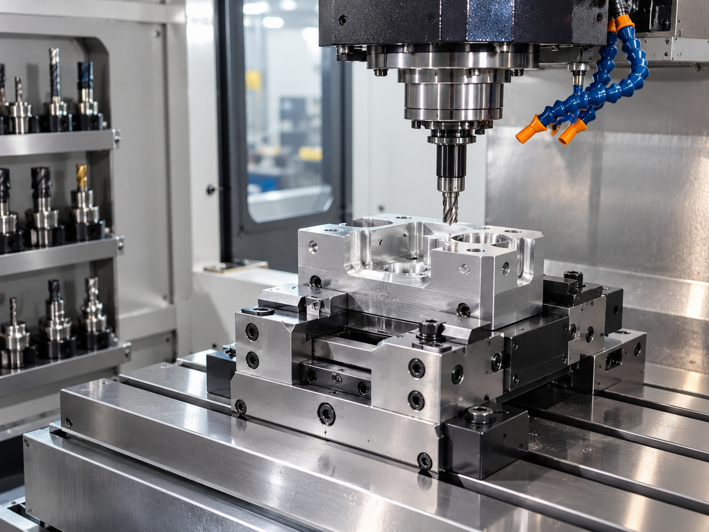
Category 01
Prismatic and 3-Axis Parts
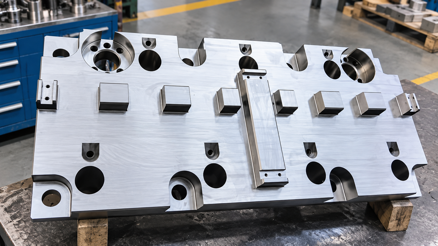
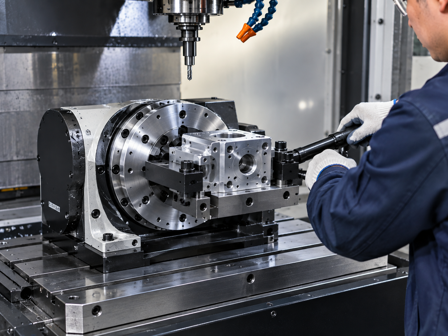
Machine vises, soft jaws, toe clamps and a modular fixture plate suit blocks and plates when the primary datum is stable. The deciding details are jaw contact, cutter clearance, chip escape and access for the second operation.
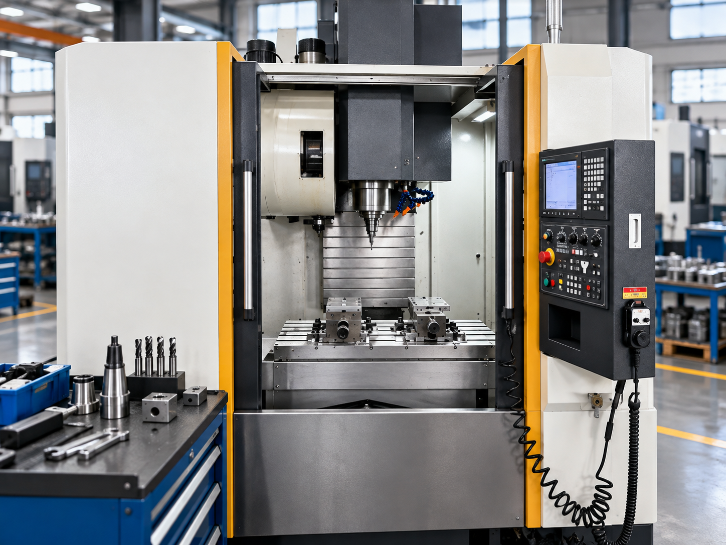
Category 02
5-Axis and Multi-Axis Parts
Low-profile workholding, a dovetail or a raised pallet can expose more faces to the cutting tool. The toolpaths, spindle envelope and collision model must be checked with the actual machine configuration.
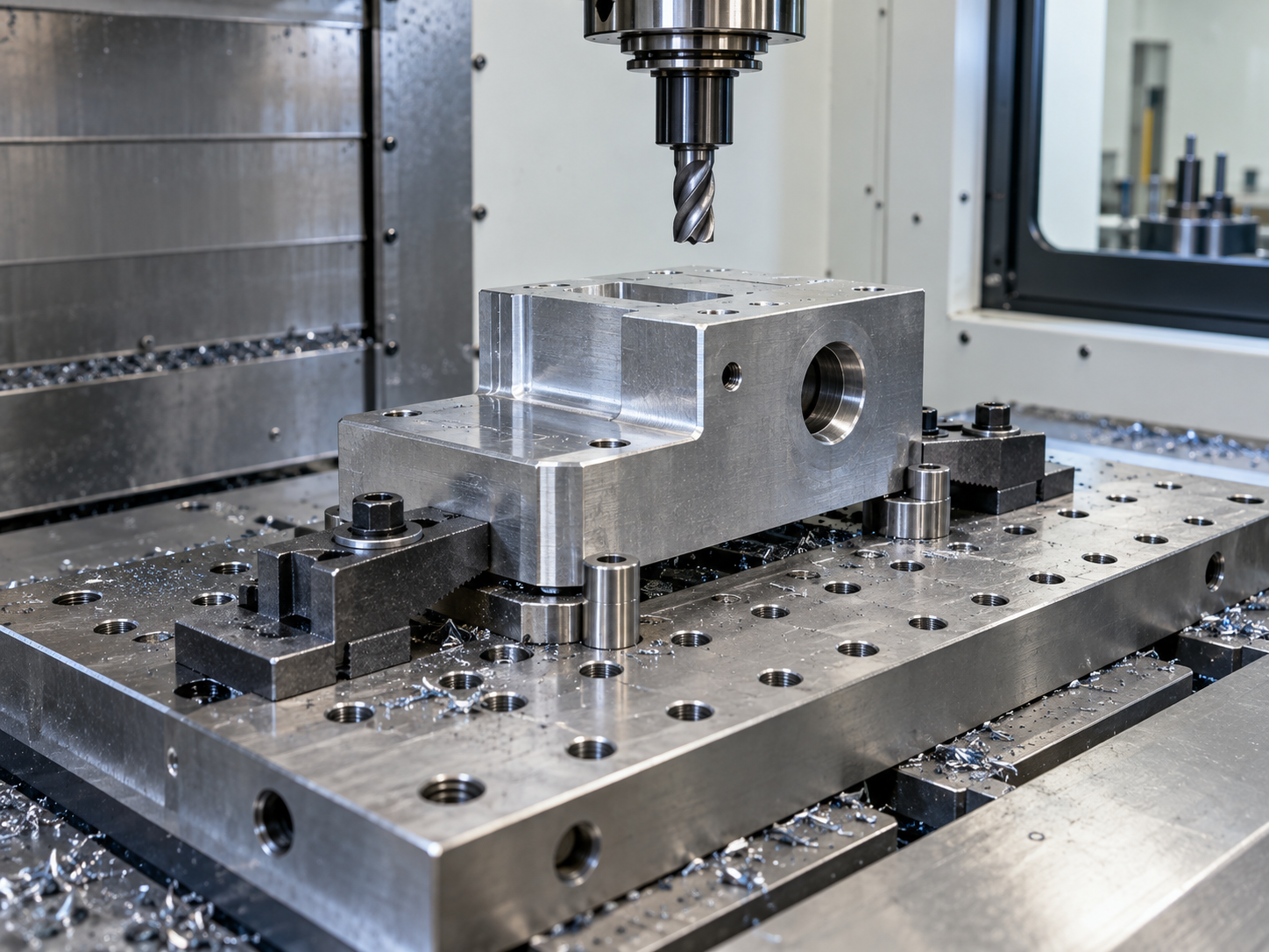
Category 03
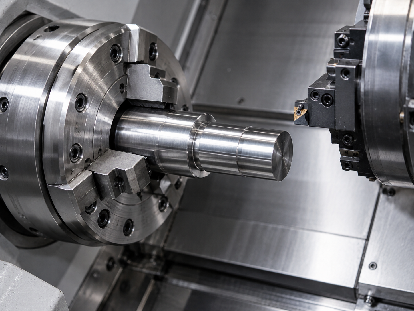
Round and Cylindrical Parts
Chucks and collets locate round stock differently from soft jaws or a bored nest. Rotary workholding also introduces speed, balance, holding-force retention and guarding inputs that a static milling fixture does not carry.
Category 04
Thin-Wall and Irregular Parts
Custom workholding fixtures use distributed support and controlled contact to reduce distortion. A hydraulic or pneumatic clamping system may improve force consistency, while mechanical clamps can remain simpler for low-volume work.
| Approach example | Best fit | Primary trade-off | Drawing input |
|---|---|---|---|
| Machine vise and soft jaws | Parallel blocks and repeat second operations | Jaw reach and part deformation | Jaw contact zone and finished-datum plan |
| Fixture plate + edge clamps | Plate work and flexible hole patterns | Setup time and tool interference | Mounting pattern, clearances and coolant path |
| Dedicated machining fixture | Irregular parts or repeat production runs | Engineering cost versus repeat volume | Annual quantity, revisions and operation sequence |
| Chuck or collet | Lathe work and cylindrical parts | Grip length, runout, speed and balance | Rotating limits and approved contact diameter |
| Vacuum workholding | Broad, thin, non-porous sheet | Seal area, leakage and cutting breakthrough | Usable sealing area and cut-through map |
Engineering Rule
The locator establishes position; the clamp keeps the workpiece seated. Asking friction alone to resist the primary cutting forces makes the setup harder to validate.
Materials for Custom Workholding Components
We machine workholding components from the metal families in your approved print. Material condition, hardness, heat-treatment state and certificate requirements belong on the request because they change tooling, grinding, wire EDM and inspection planning.
-
1
Carbon and Alloy Steels
State the exact grade, condition and hardness required for review.
-
2
Bearing Steels
State the exact grade, condition and hardness required for review.
-
3
Stainless Steels
State the exact grade, condition and hardness required for review.
-
4
Nickel-Based Alloys
State the exact grade, condition and hardness required for review.
-
5
Aluminium Alloys
State the exact grade, condition and hardness required for review.
-
Carbon Steel
State the exact grade in the drawing. Define hardness, rigidity, datum stability and any later treatment.
-
Alloy Steel
State the exact grade in the drawing. We review heat-treatment state before finish machining and grinding.
-
Bearing Steel
State the exact grade in the drawing. This route can suit wear-oriented pins, rings and locating elements when the print controls hardness and finishing.
-
Stainless Steel
State the exact grade in the drawing. Corrosion exposure and anti-galling requirements should be defined with the mating component.
-
Nickel-Based Alloys
State the exact nickel-based alloy grade in the drawing for chemical applications. We review material identity and machining route before price and schedule are released.
-
Aluminium Alloys
Scope: various aluminium alloys supplied to drawing. Lightweight plates and soft jaws still require contact-pressure and wear decisions at system level.
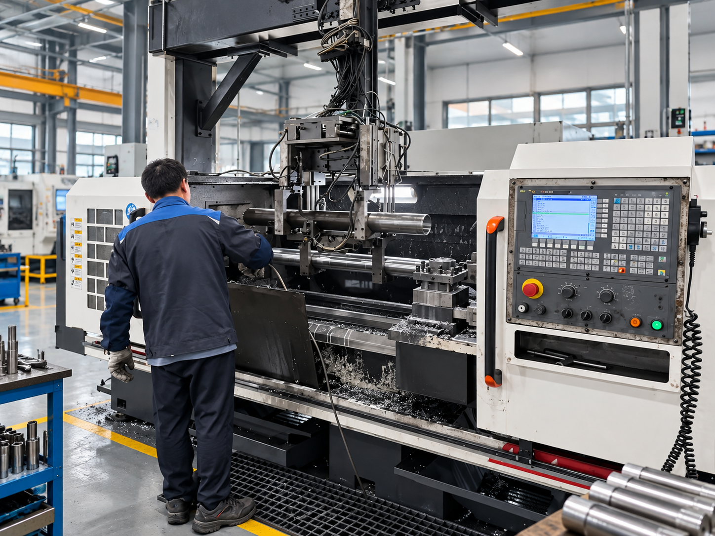
Material callout
Specify the exact grade and condition, not only “steel” or “aluminium.” If hardness is functional, state the target range and when it applies in the process sequence.
Drawing, Schedule and Acceptance Inputs
Every tolerance must point back to the feature that locates, supports, clamps or verifies the part. We confirm achievable values per feature at drawing review; no universal workholding tolerance is substituted for your design requirement.
- Revision-controlled 3D model and 2D drawing
- Part datums and fixture interface datums
- Critical features, fits and geometric controls
- Material grade, condition and hardness
- Inspection method, report scope and acceptance owner
Program fact
Company history
Established in 2006 with manufacturing in Jiashan County
Factory site
8,000 m² (86,111 ft²)
Workshop area
6,000 m² (64,583 ft²)
Machining-centre range
3-axis, 4-axis and imported 5-axis machining centres
Published scope
Quotation scope
Confirmed in the written quotation after drawing review
Timing and quantity
Confirmed in the written quotation after drawing review
Payment and shipping
Confirmed in the written quotation after drawing review
Documents and confidentiality
Confirmed in the written quotation after drawing review
Pricing and Lead Times
Price follows material, geometry, tolerance, quantity, inspection and finishing rather than a fixed catalogue rate. Scope, timing, quantity, payment, shipping, document availability and confidentiality are confirmed in the written quotation after drawing review.
| Driver | Cost effect | Useful buyer action |
|---|---|---|
| Datum and setup count | More re-location adds fixture and inspection effort | Show every operation and preserved datum |
| Contact and support geometry | Custom jaws, nests or supports add engineering and machining | Mark allowed clamp zones and finished surfaces |
| Tolerance and evidence | More critical characteristics increase process and inspection time | Separate functional controls from reference dimensions |
| Quantity and repeat demand | Dedicated tooling spreads differently across one piece and recurring lots | Give prototype, batch and annual volumes |
| Material and hardness | Tool wear, grinding and wire EDM routes change | State grade, condition and hardness window |
| Handling and access | Long loading, chip cleaning and extra operations consume machine time | Define loading direction and all cutter approaches |
Verification
Fixture Investment Check
Compare tooling cost with setup minutes saved, expected batches, parts per setup, scrap exposure, damaged-tool risk and additional inspection. The result is useful only with your shop rate and production plan, so we do not publish a universal payback percentage.
Administration
Commercial terms
Payment, shipping, confidentiality and document availability are stated in the written quotation after drawing review.
Quality Control and Inspection
We tie inspection back to the same revision and datum scheme used for manufacturing. Required document and record scope is confirmed in the written quotation after drawing review.
Controls that prevent false confidence
-
+
Freeze the revision: match the 3D model, 2D drawing and purchase order.
-
+
Identify functional datums: distinguish workpiece datums from fixture and machine references.
-
+
Agree the evidence: define critical characteristics, report format and material records.
-
+
Release against the same criteria: keep manufacturing and acceptance on one documented basis.
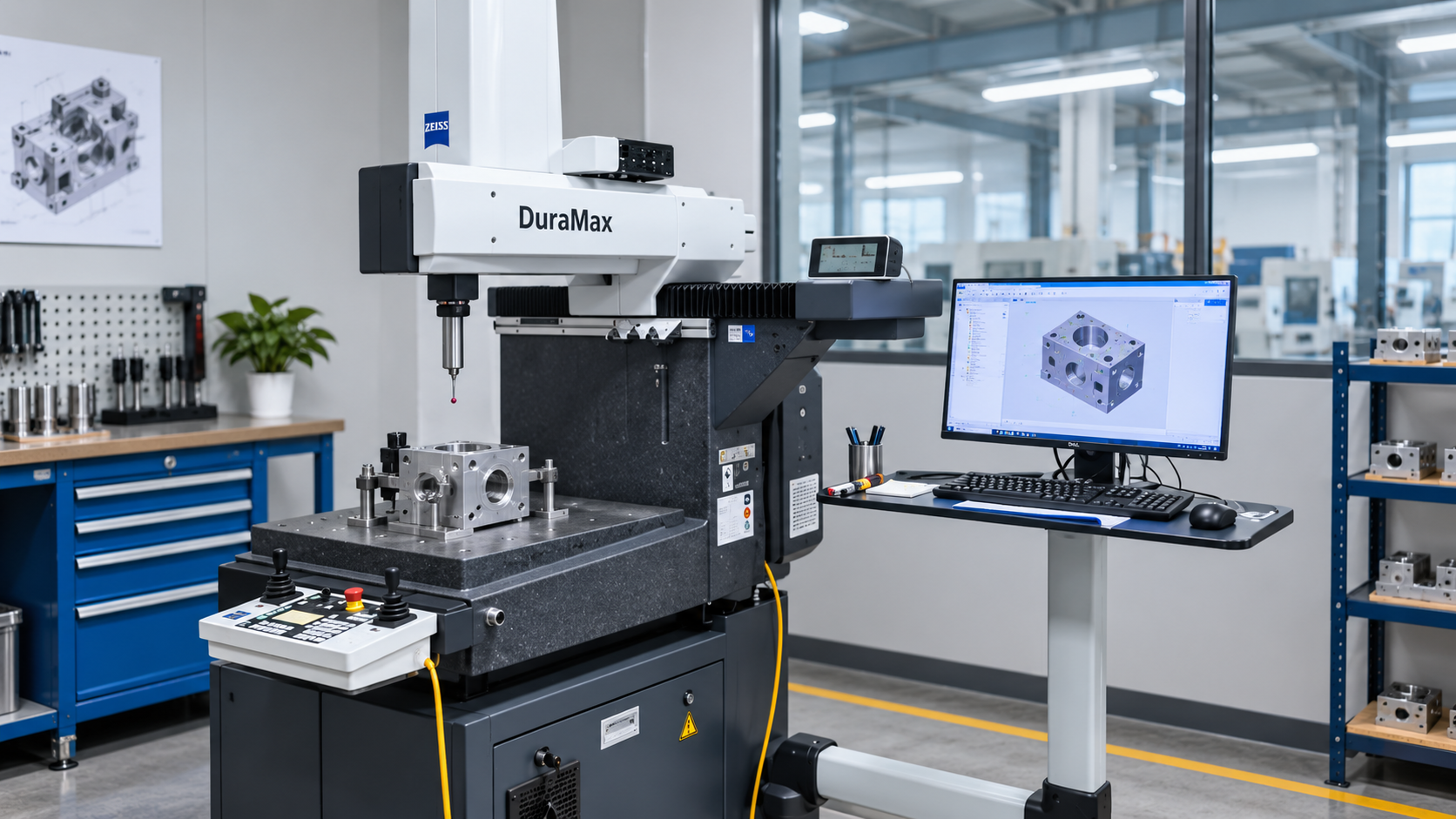
Chip and seating check
A repeatable fixture can still repeat the wrong position when a burr or chip sits under the workpiece. Relieved locators, clean-out access and a visible seating check belong in the design review.
Quality note
machine inventory proves available processes; it does not by itself prove an installed fixture’s accuracy. The acceptance plan must connect the workholding datum, machine coordinates and final part inspection.
Datum-to-Clamp Trace
The Datum-to-Clamp Trace turns a drawing into a reviewable force and accuracy path. It separates location, support, restraint, tool clearance and verification so each decision has an owner.
Send files:
include an available model and controlled drawing.
Review scope:
we identify material, manufacturing route, unclear datums and missing acceptance inputs.
Receive the quote:
price, schedule and scope are confirmed in writing after drawing review.
Approve the package:
revision, quantity, evidence and commercial terms are fixed in writing.
Manufacture to print:
we machine the approved component; the responsible system engineer retains design and validation ownership.
Release and ship:
shipping and document scope are confirmed in writing.
Machining Platform for Build-to-Print Components
Shanghai Zhenling Hardware Co., Ltd. was established in 2006 and manufactures in Jiashan County, Zhejiang Province, China. The factory occupies an 8,000 m² site with a 6,000 m² workshop.
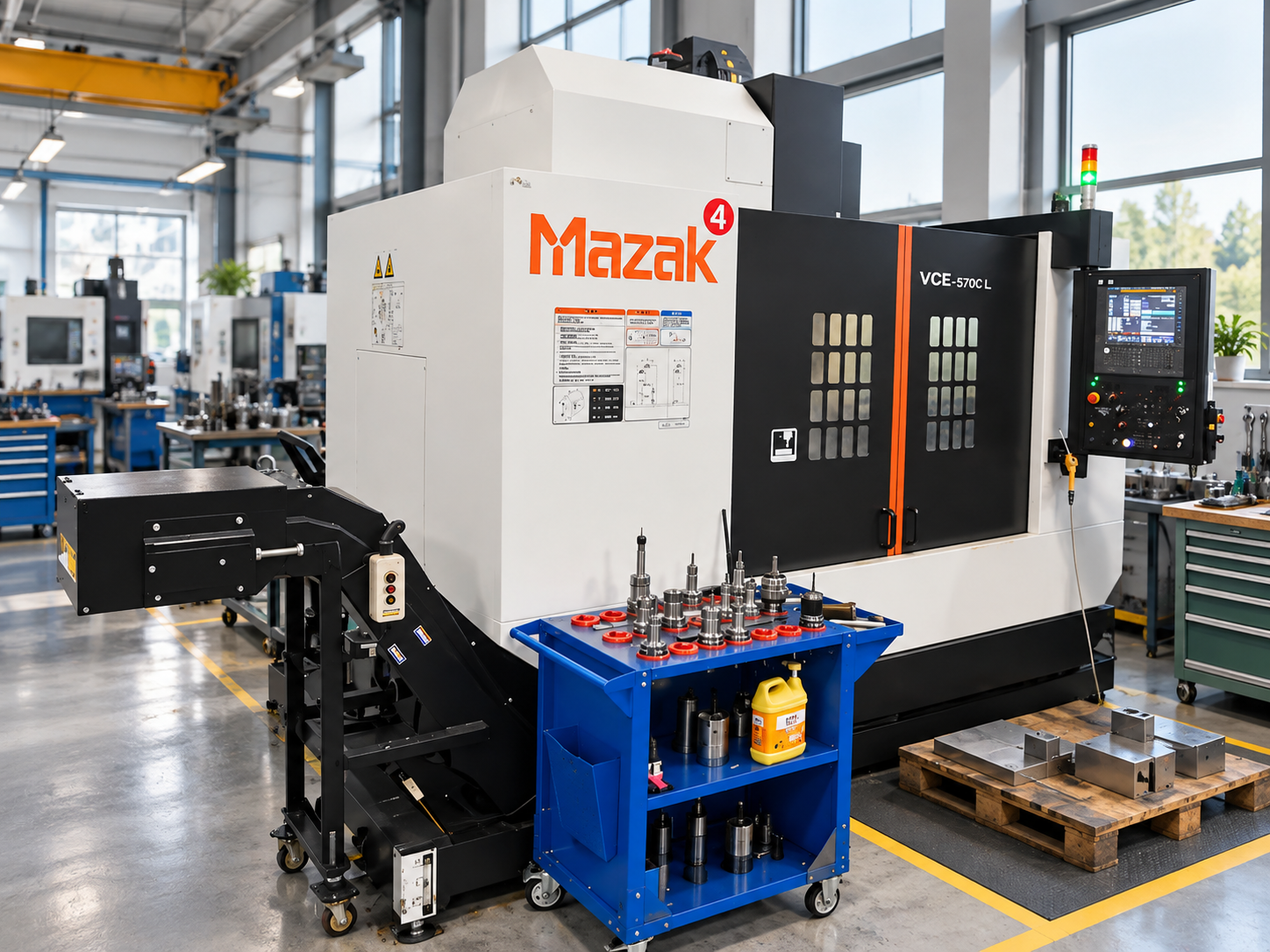
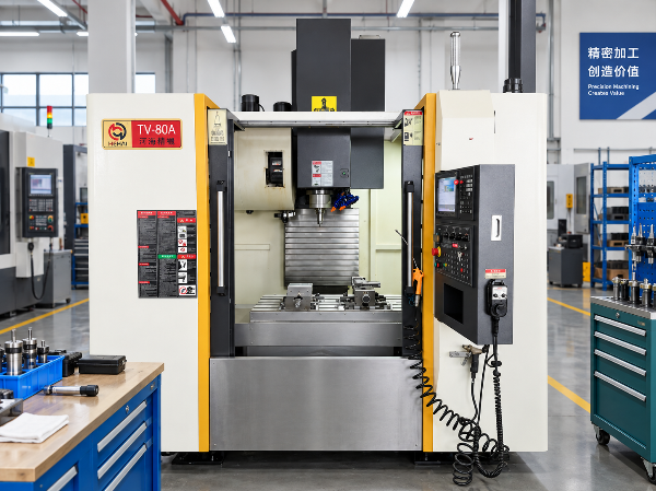
CNC machining-centre capacity for made-to-print metal components.
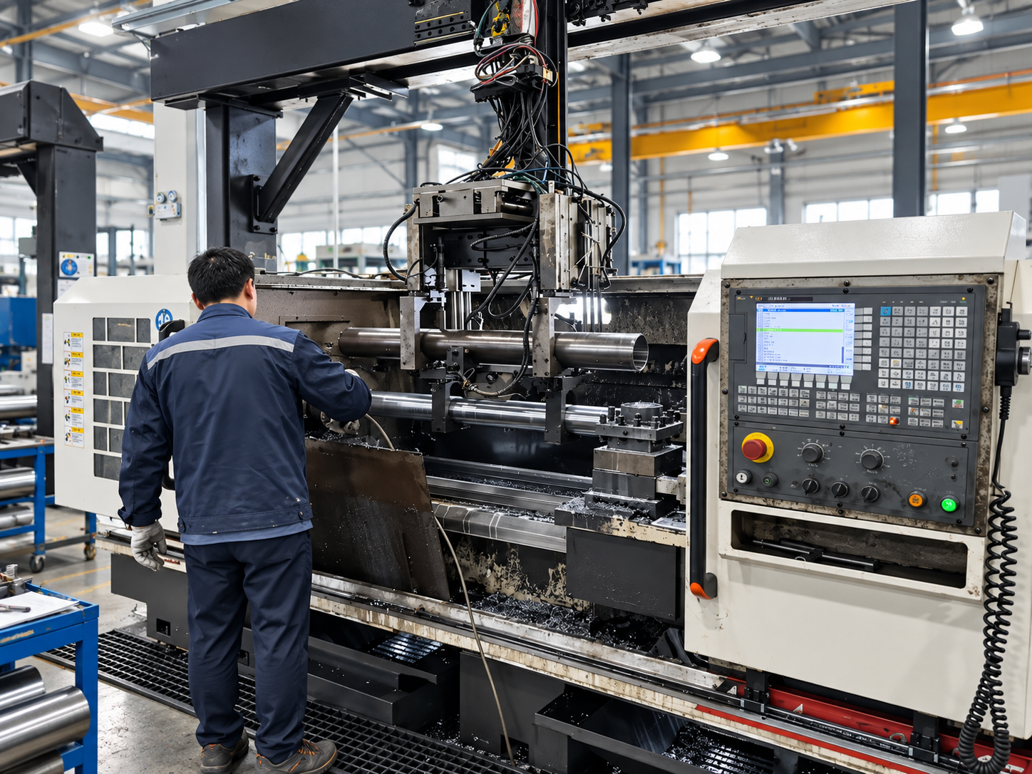
Large-part machining equipment from the client reference package.
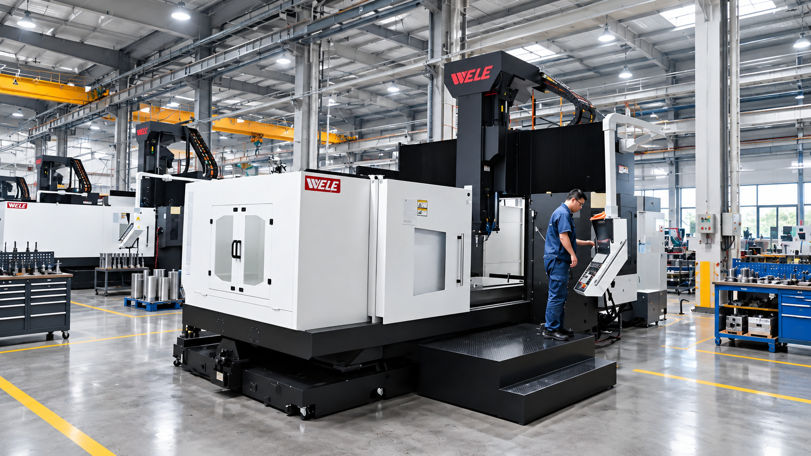
Five-axis machining-centre capability shown in client-supplied media.
Equipment categories on the floor
CNC wire-cut EDM, CNC lathes and CNC milling machines
CNC grinding, boring and radial drilling machines
3-axis and 4-axis machining centres
Imported 5-axis machining centres
This equipment base supports precision machining of approved component geometry. Suitability for unattended automation still depends on the complete machine, workholding, loading and safeguarding plan.
We manufacture the approved component geometry and can flag missing inputs during review. Fixture-system design, cutting-load calculation, rotating limits, validation and safeguarding stay with the buyer’s responsible engineer unless a separate written scope assigns them.
Check the Quote Evidence PackSafety and Responsibility Boundaries
Custom workholding is not automatically the right answer for every job. The selection must account for machine interfaces, foreseeable misuse and the installed system, especially when the workholding rotates or is power actuated.
Component manufacture is not system validation
Unlike a catalogue filter, an installed-system review must connect the machine, workpiece, clamp, cutting load and safeguarding. The reason is structural: Zhenling Metal manufactures the approved component, whereas operating limits and risk acceptance remain with the responsible system engineer unless a separate written scope assigns them.
Standard
Current safety reference
ISO 16090-1:2022 covers safety requirements for machining centres, milling machines and transfer machines, including powered workpiece clamping mechanisms. A component drawing or supplier page does not replace the risk assessment, operating limits and guarding validation for the installed machine.
| Situation | Why it works against you | Better route |
|---|---|---|
| Simple one-off block | A dedicated fixture can add more engineering than it removes | Use a standard vise or modular setup if access permits |
| Frequent design revision | Hard features can become obsolete before tooling cost is spread | Use replaceable jaws, modular locators or an adaptable fixture plate |
| Unsupported thin wall | Local clamping force can create distortion before machining | Move contact over supports or redesign the nest and restraint path |
| Rotating chuck or jaw assembly | Speed, balance, force retention, ejection and guarding become system inputs | Use validated limits from the responsible machine/workholding engineer |
| Vacuum seal interrupted by cut-through | Holding force can change as the tool opens the sealed area | Segment the vacuum zone or add a verified mechanical restraint |
CNC Workholding & Planning Tools
Workholding Approach Selector
Evaluate part geometry and production volume to determine the optimal fixturing strategy. Maximize machining stability and reduce setup times.
Access Tool →Setup Cost Comparator
Calculate the economic breakeven points between flexible standard workholding and dedicated custom fixtures. Optimize budget allocation for batch production.
Access Tool →Quote Evidence Pack Builder
Generate comprehensive, data-backed documentation to support your machining quotes. Ensure transparent and accurate technical communication with clients.
Access Tool →CNC Workholding FAQs
What is CNC workholding?
It is the combined method used to locate, support and restrain a workpiece relative to the machine and cutting tool. The system can include a vise, chuck, collet, jaws, fixture plate, locator, support, clamp, pallet or custom fixture.
What is the difference between locating and clamping?
Locators establish the repeatable reference position. Clamps keep the workpiece seated against those references and resist motion not already carried into solid supports.
Which workholding method fits a thin-wall component?
Start with broad support under each clamp contact and keep force away from unsupported walls. The exact contact area and clamping force require the part geometry, material, cutting loads and allowable distortion.
Is vacuum workholding a replacement for mechanical clamps?
Not universally. A vacuum table fits broad non-porous contact areas, but leakage, cut-through, surface condition and lateral cutting forces can require segmented zones or mechanical backup.
Will every production run benefit from a dedicated fixture?
No. A dedicated machining fixture earns its place when repeat volume, access, setup time and quality risk outweigh its engineering and manufacturing cost.
What should be sent for a custom workholding component quote?
Send an available model and controlled drawing, revision, material, quantity, operation sequence, datum scheme, contact restrictions, machine interface and acceptance requirements. Timing and scope are confirmed in the written quotation after drawing review.
Can Zhenling manufacture one prototype fixture component?
A prototype request is reviewed against the drawing and required scope. Quantity and timing are confirmed in the written quotation after drawing review.
Which materials can Zhenling machine?
We machine carbon and alloy steels, stainless steels, bearing steel, nickel-based alloys and aluminium alloys. The exact grade, condition and hardness must be stated on the drawing package.
Does Zhenling provide fixture-system design and safety validation?
Our published offer is build-to-print component manufacturing and drawing-scope review. Load calculations, rotating operating limits, system validation and safeguarding remain with the responsible engineer unless a separate written contract assigns that work.
Which inspection records are available?
State the required characteristics and record scope in the RFQ. Document requirements are confirmed in the written quotation after drawing review.