

Milling Operations: Diagrams, Examples and Key Terms
Milling operations respond to drawing features by converting them into movements of controlled cutting tools. For example, a face becomes a face-milling question, a closed cavity becomes a pocketing question, and a narrow channel becomes a slotting question. This guide will help you to name the most likely operation and identify as-yet undetermined access, datum, workholding, and inspection issues.
- Engineer-reviewed quotes within 24 hours
- Prototype parts in 5–7 days
- Single-piece or no fixed MOQ
- 3D CAD plus a dimensioned 2D drawing
Operation name ≠ complete process plan. The same feature may need different cutters, toolpaths or setups when material condition, holder clearance, tolerance, surface finish or batch strategy changes.
“Operation terminology is useful only when it leads to a setup that can be proved and a feature that can be inspected.”
— Zhenling Engineering Team
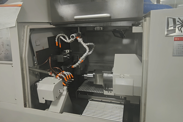
Feature-first: Faces, shoulders, slots, pockets, profiles and threads
·
Process layers: Operation, cutter, path, setup and verification
·
Machine scope: 3-axis, 4-axis and imported 5-axis machining centers
·
Material scope: Steels, stainless steels, aluminum and special alloys
·
Drawing intake: 3D CAD plus a dimensioned 2D drawing
·
Manufacturing base: Non-standard metal production since 2006
·
Feature-first: Faces, shoulders, slots, pockets, profiles and threads
·
Process layers: Operation, cutter, path, setup and verification
·
Machine scope: 3-axis, 4-axis and imported 5-axis machining centers
·
Material scope: Steels, stainless steels, aluminum and special alloys
·
Drawing intake: 3D CAD plus a dimensioned 2D drawing
·
Manufacturing base: Non-standard metal production since 2006
·
SYSTEM / PROCESS
Milling Operations at a Glance
At the first step in the Feature-to-Operation Review Board, we consider the surface that needs to be generated. From this surface, we provide a candidate operation and a question that prevents the operation from becoming a bad process assumptionsource. A type of milling operation can also be named for the cutter arrangement: side milling, plain milling, form milling, gang milling, saw milling, straddle milling, angle milling and helical milling.
| Drawing Feature | Candidate Operation | Best Fit | Check First |
|---|---|---|---|
| Broad datum face | Face milling | Accessible planar surface | Cutter coverage, interrupted edges, clamping and flatness intent |
| Long external plane | Peripheral, plain or slab milling | Surface generated by the cutter circumference | Spindle orientation, arbor support and chip clearance |
| Shoulder or local flat | End or shoulder milling | Floor and wall features with axial and radial cutting | Corner radius, wall access and finishing allowance |
| Narrow channel or keyway | Slot milling or keyway milling | Defined width with open tool access | Full-width engagement, chip evacuation and tool deflection |
| Closed cavity | Pocket milling | Internal floor and walls | Entry strategy, minimum internal radius, depth and chip removal |
| Curved external form | Profile or contour milling | 2D or 3D boundary surfaces | Ball-end or corner-radius geometry, stepover and axis access |
| Threaded feature | Thread milling | Programmed helical path with suitable diameter and access | Thread standard, pitch, reach and comparison with tapping or turning |
| Angled face or groove | Angular milling | Feature set at an angle to a reference plane | Cutter form, setup orientation and datum relationship |
Material Specifications
Milling Notes for Common Metal Groups
The selection of material has much more importance than the selection of spindle speed. The family of alloys, the temper or heat treatment, the condition of the stock, the hardness, the behavior of the chips, and the residual stress affect the selection of the cutter, its engagement, the workholding, and the inspection.
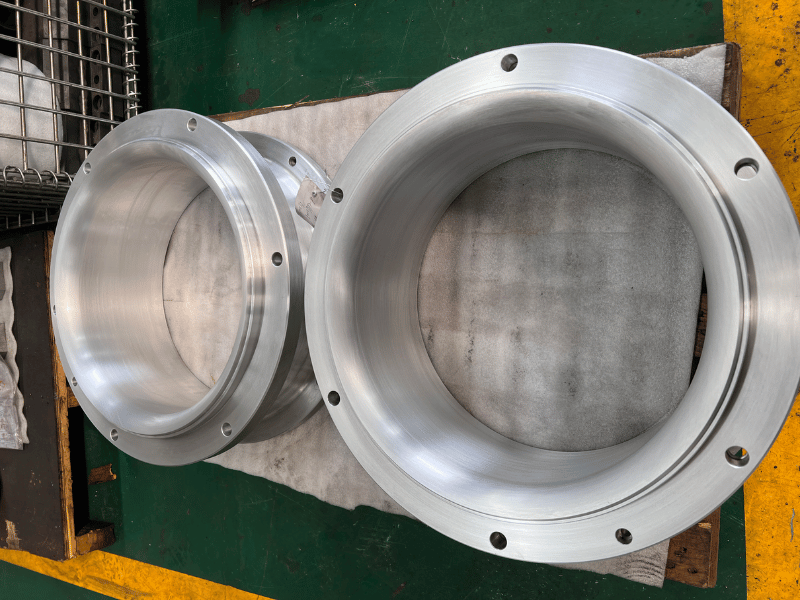
Aluminum alloys
Aluminum often rewards open flute space and reliable chip evacuation, while thin walls and large pockets make rigidity and residual stress visible. Burr direction, stock condition and finishing allowance should be reviewed before a toolpath is fixed.
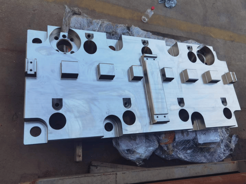
Carbon and alloy steels
For grades such as 20#, 45#, Q235A, Q345D, 12CrMoV, GCr15, 25CrMo and 42CrMo, the heat-treatment condition belongs beside the grade. Hardness alone is not a reliable machinability verdict; microstructure, scale, rigidity and tool engagement also matter.
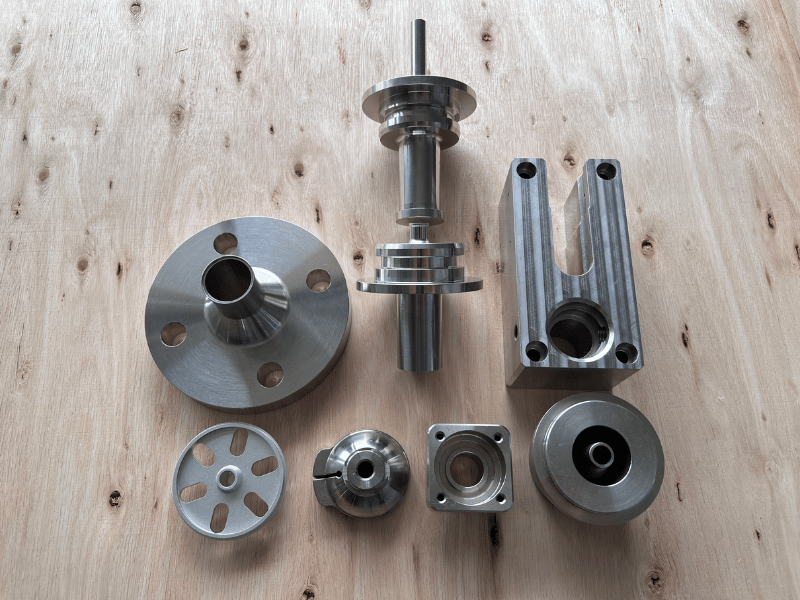
Stainless steels
Zhenling’s supplied material list includes 303, 304, 304L, 316, 316L and 321. Consistent engagement, heat control, edge condition and a stable finish pass deserve attention where work hardening or burr formation is a concern.
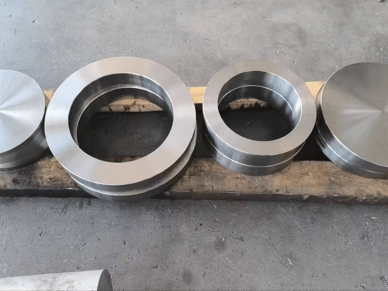
Nickel-based and special alloys
Grades such as C276 and 904L concentrate the review on heat, tool wear, edge condition and repeatability. A conservative path does not mean guessing a slow feed; it means selecting parameters against the actual grade, stock and machine-tool system.
Cutter and Toolpath Decisions
Selection of a milling cutter is part of a system, not an association of one name with one operation. The workpiece interacts with, and influences, the diameter, edge geometry, insert or solid-tool construction, flute count, coating, holder, overhang and machine feed capability of a cutter. For broad side faces, a side milling cutter or plain mill is used for milling, while cutter form and mounting separate one milling technique from another.
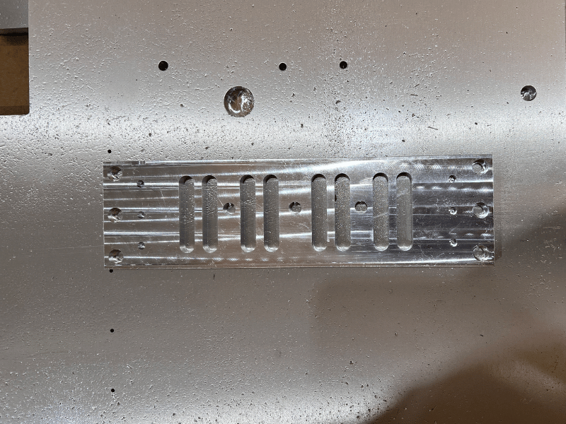
Parameters that describe the cut
- Spindle speed describes the rotation of the cutter, whereas cutting speed refers to the cutter and the material.
- Feed rate describes the travel of the machine, whereas feed per tooth relates travel and engagement of cutting edges.
- Axial depth of cut and radial width of cut define the extent of engagement in two dimensions.
- Stepdown and stepover describe the toolpath in terms of depth and lateral coverage.
Why the distinction matters. Two programs can use the same end mill yet load it differently because engagement, chip thickness and time in the cut are different. The correct settings come from the complete machine, holder, cutter, material and workholding system.
Face mill and end mill checkpoints
- A face mill cuts peripherally and axially across the surface to generate a plane. Approach angle and diameter of face mill cutters provide options to change cutter coverage and the direction of cutting forces.
- The cutting edges of an end mill are located on the flutes as well as at the end. One end mill may be used to rough a pocket and another to finish the wall or the floor.
- Even the most complex milling cutter requires a clearance path for chips and adequate flute diameter and a holder. The name of the milling cutter does not address these issues.
Face mill vs end mill: the first shortlist follows feature size and access, then the machinist checks machine power, holder clearance, cutting-tool geometry and workholding. Harder materials do not choose the cutter alone, and a CNC machine does not remove the need for system review.
PROCESS ENGINEERING
Drawing, Datum and Setup Inputs
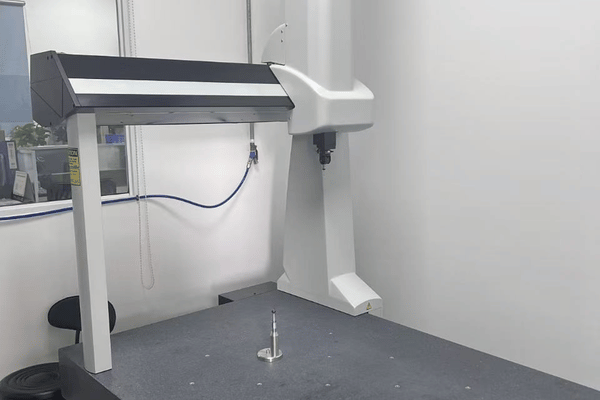
A useful milling review connects the geometric definition to a repeatable work zero and an inspection method. Zhenling works from 3D CAD plus a dimensioned 2D drawing so nominal geometry and acceptance requirements can be reviewed together. This manufacturing process review also connects machine operations and machine parts to the same datum and inspection chain.
| Input or scope | Declared review basis |
|---|---|
| 3D model | Nominal surfaces, feature access, stock envelope and collision review |
| 2D drawing | Critical dimensions, tolerances, datums, finish, threads and notes |
| 3-axis machining | Features accessible from fixed tool directions with planned repositioning |
| 4-axis machining | Indexed or coordinated access reviewed against clamping and datum transfer |
| 5-axis machining | Multi-direction access reviewed against holder reach, collision and inspection strategy |
| 5–7 day prototype window | Starts after drawing approval for prototype parts |
| 1-piece entry | Single-piece or no fixed MOQ for drawing-led review |
| 24-hour quote response | Engineer-reviewed quotation returned on business days |
Datum transfer before tool selection
- Identify the surfaces of the part that locate the element in the assembly.
- Choose workholding that maintains the element and exposes the feature without weakening the clamp.
- Define work zero and how it transfers from one setup to the next.
- Match critical features to an accessible measurement method.
PROCESS RESOURCES
Cost and Lead-Time Drivers
Custom work is priced by drawing: the material, geometry, tolerance, quantity, setup, and machining time determine the final quoted price.
Evidence before price. The risk of an incomplete quote rises because hidden setups, tool access and inspection scope are discovered after award. Zhenling reviews the drawing and returns an engineer-reviewed quotation within 24 hours on business days.
Quote response
We return engineer-reviewed quotes within 24 hours on business days.
Prototype schedule
Prototype parts ship in 5–7 days after drawing approval.
Order entry
Single-piece or no fixed MOQ keeps the first manufacturing review practical.
QUALITY CONTROL
Process Risks and Verification Points
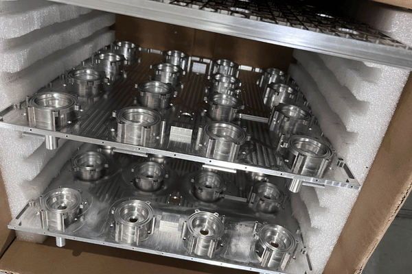
Most milling defects are the result of the relationship between the cutter, holder, toolpath, workholding and the material. A symptom table relates the observed defect to a specific feature for a given cutter, holder, and toolpath.
| Observed symptom | Likely review area | Verification point |
|---|---|---|
| Chatter or vibration | Tool overhang, holder condition, workholding, engagement and machine dynamics | Compare sound and surface pattern with runout, clamp stability and tool-wear evidence. |
| Burrs or damaged edges | Cutter exit, edge geometry, tool condition and deburring note | Inspect the called-out edge condition at first article and during the run. |
| Dimensional drift | Datum transfer, thermal state, tool wear and stock movement | Measure critical features at defined intervals against the same datum scheme. |
| Wall taper or corner error | Tool deflection, reach, finishing allowance and internal radius | Separate rough and finish measurements and review the accessible inspection method. |
| Surface marks | Chip recutting, path transition, insert condition and finish-pass engagement | Check surface direction and location against the cutter path and entry or exit point. |
PROCESS ENGINEERING
Milling Plan Development
We develop a plan based on the drawing and not a favorite mill. This sequence establishes a relationship between programming, setup and inspection to the same feature. The CNC milling process then turns that sequence into operations like roughing, finishing, drilling and inspection.
A faster setup device is not a substitute for standardized offsets and disciplined datum transfer.
- Understanding the definition – consider the dimensions, geometry, tolerances, surface finish, material and assembly.
- Access and workholding planning – plan clamp placement, holder clearance, work zero and datum transfer for remaining setups.
- Select operations: divide removal of material into roughing, semi-finishing and finishing operations where the feature requires it.
- Prove the program: use a controlled dry-run to determine if the offsets, approach, clearance and toolpath are acceptable before cutting.
- Check the first part: measure the important features against the detail drawing before continuing the batch.
- Control the run: monitor tool wear and inspect critical features during the process, especially after a change in program, tool or setup.
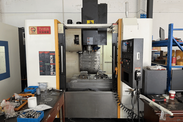
From parameter to evidence
Plan
Operation, cutting tool, toolpath, workholding and inspection points share one feature list.
Prove
Work offsets, clearance and approach are checked before normal production execution.
Inspect
First-part and in-process checks follow the drawing’s critical characteristics and the planned datum scheme.
APPLICATIONS
Examples from Non-Standard Metal Components
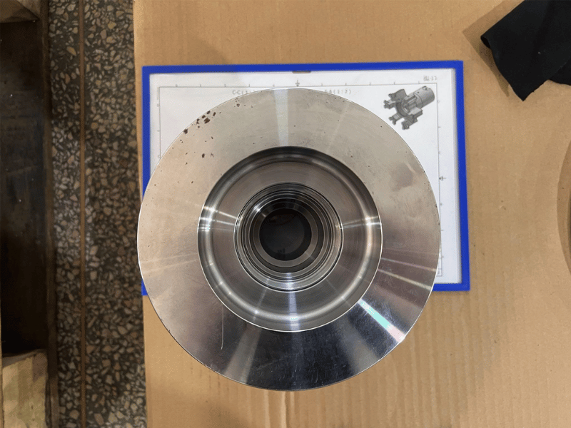
Zhenling manufactures made-to-print components such as flanges, rollers, bent pipes, valve bodies, plugs and complete machine assemblies. The examples below illustrate candidate operations; the drawing decides the final route. The types of CNC milling operations below show how a CNC milling operation can combine several feature-specific cuts.
Flange datum face
Candidate: face millingReview interrupted holes, clamping, sealing-face intent and whether the face establishes a later datum.
Roller keyway
Candidate: slot or keyway millingReview width, depth, end condition, tool access and the relationship to the roller axis.
Valve-body cavity
Candidate: pocket millingReview entry, corner radius, chip evacuation, wall reach, finishing allowance and sealing features.
Plug wrench flats
Candidate: side or end millingReview orientation to the turned diameter, flat-to-flat size and workholding repeatability.
Curved housing profile
Candidate: profile millingReview holder clearance, scallop direction and inspectable reference features. May involve multi-axis access.
Large threaded port
Candidate: thread millingReview diameter, pitch, blind depth, material and access before selecting between tapping or a turning operation.
SYSTEM CAPABILITY
Manual, CNC and Multi-Axis Boundaries
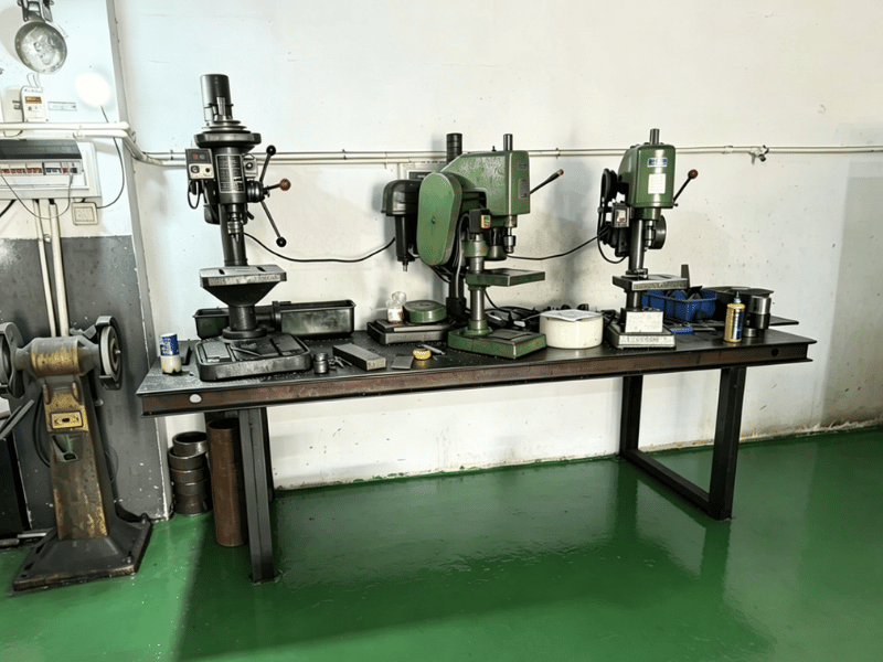
Manual, programmed and multi-axis milling share cutting principles, but differ in the control conditions. Machine drive, guarding, work offsets, collision avoidance and setup strategy affect how a direction or an operation can be evaluated. Vertical and horizontal machine configurations differ: a vertical milling machine, a horizontal milling machine or a horizontal mill may support the same machining process, but the type of milling machine changes arbor support, access and workholding.
More controlled axes are not a substitute for workholding, reach, collision and inspection planning. The trade-off is fewer repositioning steps against a more demanding machine and program envelope.
| Context | Best for | Boundary to keep visible |
|---|---|---|
| Manual milling | Direct operator control, repair work and simple one-off features | Backlash, operator exposure and machine-specific safeguards matter to direction choice. |
| 3-axis CNC milling | Programmed faces, pockets, shoulders, slots and profiles from planned orientations | Repositioning can add datum-transfer and setup error. |
| 4-axis milling | Indexed or coordinated access around a part | Rotary workholding, centerline definition and fixture clearance remain critical. |
| 5-axis milling | Multi-direction surfaces and reduced repositioning for accessible geometry | More axes do not remove holder reach, collision, workholding or inspection constraints. |
Climb and conventional directions
Climb milling
Chip thickness begins high and decreases through engagement. It is often selected on suitable CNC systems for chip flow and cutting behavior, but backlash and system dynamics must be checked.
Conventional milling
Chip thickness begins near zero and increases through engagement. It may be useful with rough surface scale or selected finishing conditions, and published tests show that no direction owns the best finish in every setup.
Selection rule: compare machine condition, workholding force direction, surface condition, tool deflection, chip evacuation and finish evidence. Climb milling is not always the best finish direction, and conventional milling is not always the safer or more stable direction.
ENGINEERING UTILITIES
Milling Operations Engineering Tools
Feature-to-Operation Selector
Identify the most appropriate milling operation based on your specific drawing features and geometry constraints.
Setup Strategy Comparison
Evaluate workholding, datum transfer, and machine configurations to minimize repositioning errors and optimize production.
Drawing Readiness Score
Audit your 2D and 3D CAD files for critical manufacturing inputs before requesting a formal process review.
SYSTEM INTAKE
Send Your Drawing for a Milling Process Review
Share the feature, condition of material, quantity and acceptability. We assess the likely milling operations, setup constraints and drawing deficiencies before the route is finalized; the related CNC milling services page outlines the commercial service scope.
Required Inputs
- 3D CAD plus a dimensioned 2D drawing
- Material grade, temper or heat-treatment condition
- Critical datums, tolerances and inspection expectations
- Surface finish, coating, heat treatment and edge notes
0110001001101111011100100110111100101101
RESOURCES
FAQs About Milling Operations
Common groups include face, peripheral or plain, end, shoulder, side, slot, keyway, pocket, profile, thread and angular milling. The useful classification starts with the generated feature and cutter-axis relationship. These various milling groups represent a different milling technique or cutter arrangement, not a promise that every machine supports every route.
In face milling, the cutter axis is perpendicular to the generated face. In peripheral milling, cutting edges on the circumference generate a surface parallel to the cutter axis.
A broad accessible plane may favor a face mill, while pockets, local faces and shoulders may favor an end mill. Cutter coverage, machine power, fixture access, corner requirements and the finish plan can change that shortlist.
Yes. A valve body can combine a milled datum face, pocket, sealing groove, mounting holes, threaded ports and a final profile, with roughing and finishing separated where control requires it.
Provide material grade and condition, dimensions, tolerances, datums, surface and edge notes, threads, finishing requirements, quantity and inspection expectations. A 3D CAD model plus a dimensioned 2D drawing gives programming and acceptance teams complementary information.
Clamps must resist cutting force without blocking the cutter or holder. Reorienting the part also changes work zero, datum transfer and the relationships that must be re-established.
It can reduce repositioning when geometry and access support it, but it does not eliminate every setup. Workholding, holder clearance, stock access, collision control and inspection still define the practical route.
We return engineer-reviewed quotes within 24 hours on business days. Prototype parts ship in 5–7 days after drawing approval, subject to the approved drawing and quoted scope.
Single-piece or no fixed MOQ applies to the drawing-led review route. Send the quantity band because setup share, tool life and repeatability planning change between one prototype and a recurring batch.



