

CNC Metrology for Precision Machined Parts
Quotation & Prototypes
Complex-job quotations are reviewed by an engineer and returned within 48–72 hours on business days. Prototype orders start from 1 piece. STEP or IGES models with a 2D PDF drawing accepted. A dimensional inspection report ships with your order.
Metrology & Setup
CNC metrology connects drawing review, machining setup and final dimensional inspection around the features that control fit and function. Send the revision, datum scheme, critical characteristics and required report so the inspection scope is clear before production.
Confidentiality
Your drawings are handled as confidential; an NDA is available on request before drawing review.
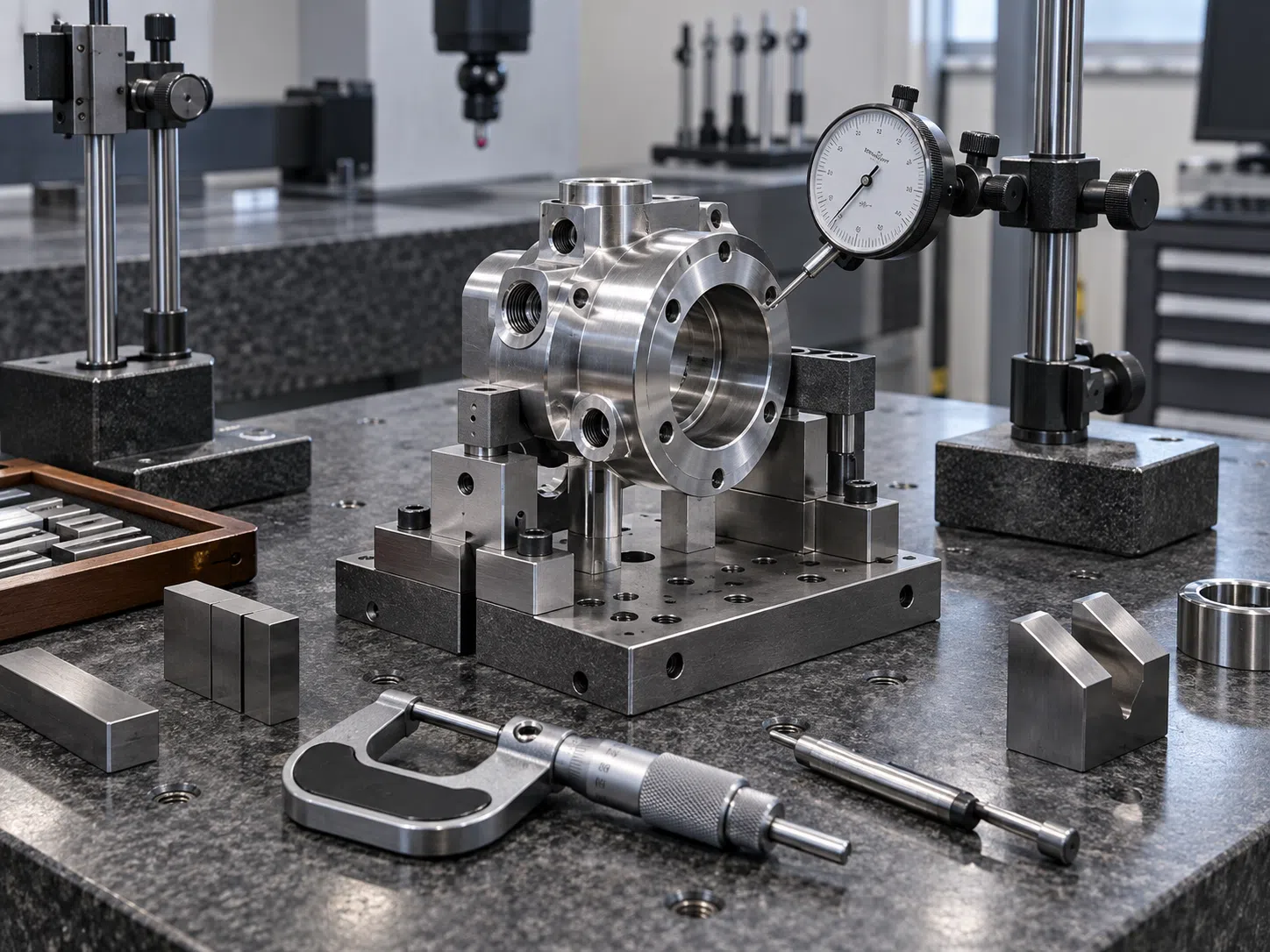
- Complex-job quote 48–72 hours on business days
- Prototype entry Orders start from 1 piece
- Drawing package STEP or IGES with a 2D PDF
- First article Can be defined before batch release
- Shipment record Dimensional inspection report
- Trade terms EXW, FOB or DDP
Measurement Methods for Machined Parts
Good CNC metrology starts with a feature, not the machine tool. Our engineering review covers access, datum control, surface state, expected tolerance, fixture influence and the data the buyer needs before choosing a measuring tool or fixing a CNC machine setup. When a feature is inaccessible, flexible or better described by a functional gauge, a fully automated option can be the wrong choice.
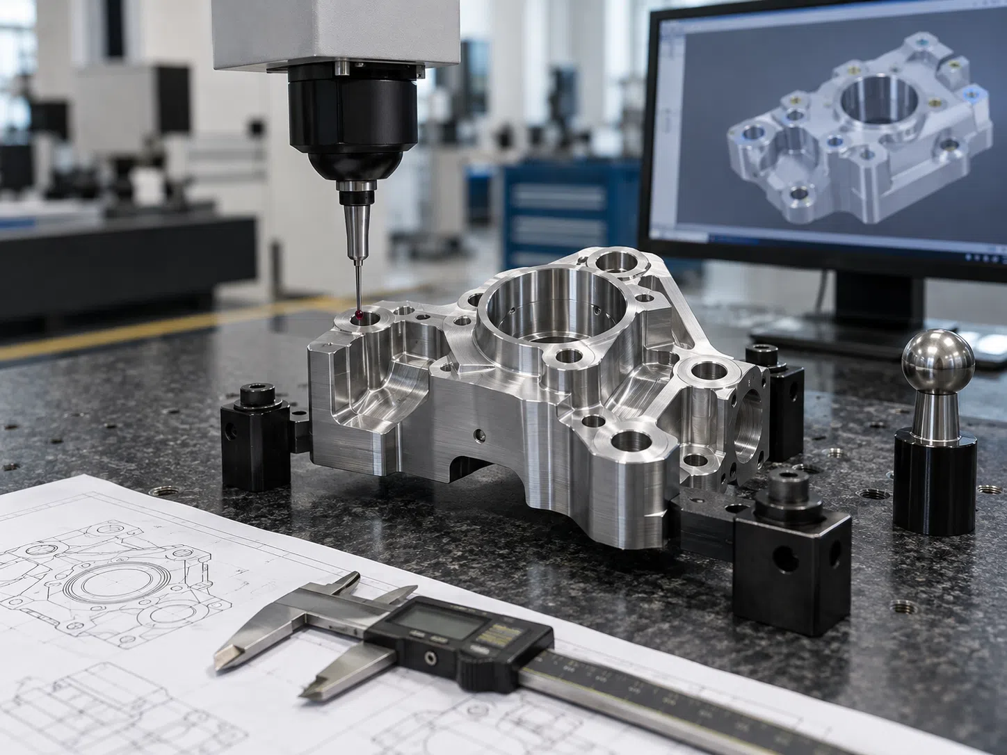
Coordinate measuring machine
A CMM supports coordinate measuring of position, profile, orientation and related 3D geometry against a defined datum reference frame. Probe choice, point strategy and setup still need to match the machined part.
Hand gage and gauge checks
A calibrated micrometer, caliper, dial indicator, bore gage or functional gauge may be a better tool for accessible sizes and quick process checks. A simpler method is often easier for a machinist to repeat at the machine.
Optical and non-contact routes
For small edges, profiles or surfaces that are hard to access, an optical comparator, vision systems, laser scanner or a 3D scan may be an option. Where non-contact inspection or CT scanning is needed, the method and supply route are confirmed in the quotation.
Surface and rotational checks
Surface roughness, runout and other spindle-related features may necessitate a surface tester, indicator or dedicated fixture instead of a CMM. The inspection follows the question the measurement seeks to answer.
Two focused metrology resources

GD&T Symbols and Basics
Use this page to read feature-control frames, datum references and common geometric controls before the drawing is released.
Open GD&T Symbols and Basics →
Dimensional Inspection
Review the methods available, the content of the report and the inputs required to define dimensional inspection or CMM inspection for a specific part.
Open Dimensional Inspection →Material Behavior in Measurement Planning
The drawing dimension is only meaningful when the state of the material is known. We machine steels, stainless steels, aluminum alloys, nickel based alloys and other special metals, and then match inspection setup to stiffness, temperature response, surface and hardness.
-
Carbon and low-alloy steels
20#, 45#, Q235A and Q345D have different strengths and machining responses. Datum faces, burr and any heat-treatment state should be defined prior to measurement.
-
Bearing and alloy steels
GCr15, 25CrMo, 42CrMo and 12CrMoV may require hardness and process state recorded with the inspection lot. Thin sections and long shafts also need fixture force checked against the free-state requirement.
-
Stainless steel series
303, 304, 304L, 316, 316L and 321 may have different machining and surface-finish responses. Clean contact surfaces and a stable support scheme help separate part form from setup effects.
-
Aluminum alloys
ISO 1:2022 supplies the dimensional reference-temperature concept; aluminum’s thermal response still makes part temperature and handling time important when the tolerance is narrow. The converted inch and millimeter values are rounded to fit the level of precision as defined by the original specification.
-
Nickel alloys and special materials
C276, 904L and nickel based chemical service alloys may present tool wear and surface issues during machining. The inspection should distinguish the cutting marks, the state of the coating and the actual geometric requirement.

Another specified grade
Please send the material grade, condition, hardness requirement and drawing.We confirm machining and measurement needs in the written quotation before stock is cut.
Surface State and Inspection Readiness
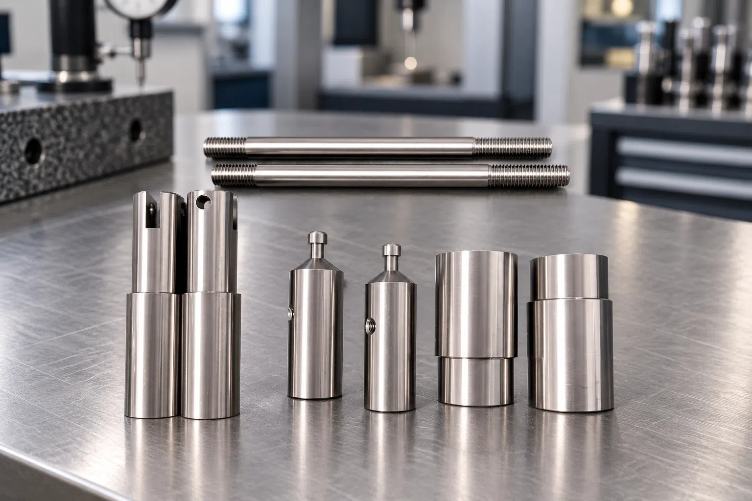
The feature measured before grinding, coating or stress relief is not necessarily the feature that the buyer receives. As such, the inspection and final surface condition should be addressed in the quote.
| Surface or process state | Inspection effect | Drawing input | Method response |
|---|---|---|---|
| As-machined | Burrs and tool marks can alter edge and contact readings. | State edge-break and surface-finish requirements. | Clean, deburr and measure the defined feature. |
| Ground feature | Final size and form follow the grinding operation. | Identify the finished datum and final tolerance. | Measure after grinding unless an in-process check is ordered. |
| Coated or plated surface | Layer build changes size and can mask the base surface. | State whether dimensions apply before or after coating. | Place inspection at the contractual surface state. |
| Heat-treated part | Distortion can change flatness, position and runout. | Define final hardness and measurement stage. | Use post-treatment verification for release features. |
| Flexible or thin wall | Contact and fixture force can move the feature. | Define free-state or constrained-state acceptance. | Control support and probe force in the method plan. |
| Reflective or fine edge | Contact and optical methods may resolve different boundaries. | Define the feature and required edge interpretation. | Compare optical, vision and contact options before programming. |
Practical value of an agreed surface state
Freezing surface state before inspection avoids paying twice for programming, fixturing and report setup after a late requirement change. It also minimizes vague release decisions.
Tolerances and Measurement Conditions
We inspect to the released drawing and the order-specific measurement scope. A universal CMM accuracy number would hide the effects of feature geometry, sampling strategy, fixture, probe, environment and the selected decision need.
-
Drawing packOne released 2D PDF revision plus the matching 3D STEP or IGES modelPrevents the CMM program and inspection report from using different design states.
-
Datum structurePrimary, secondary and tertiary references; use a 3-2-1 setup only where it represents the functional schemeControls alignment, degrees of freedom and repeatability.
-
Reference temperatureISO 1:2022 uses 20 °C (68 °F) as the dimensional-measurement reference conceptUse that reference context where thermal expansion can affect the result.
-
First articleDefine at least 1 sample, the ballooned features and the release authorityKeeps first-article inspection separate from a first-piece process check.
-
Full inspectionState whether 100% means every defined feature, every part, or bothThe three scopes carry different program time and report volume.
-
Lot sampling exampleA buyer may request 5 of 50 pieces; the actual rule is buyer-defined and written into the orderThe order records the agreed quantity, selection method and release authority.
-
Display resolution exampleReporting to 0.001 mm is a display choice, not proof of a 0.001 mm tolerance or accuracyResolution, uncertainty and tolerance are different quantities.
-
Near-limit resultIdentify the applicable contractual or ISO 14253-1 default decision rule and uncertainty treatmentA measured value alone does not settle every conformity decision.
Inspection Scope, Quotations and Lead Times
Inspection price follows programmed feature count, geometric complexity, access, fixture needs, sample quantity, method and report depth. There is no fixed price list for a made-to-print inspection scope.
Quotes are returned within 48–72 hours for complex jobs on business days, reviewed by an engineer. Prototype orders start from 1 piece, and first-article inspection can be defined before batch release.
- We work from STEP or IGES models with a 2D PDF drawing.
- We ship EXW, FOB or DDP; other Incoterms can be requested in the enquiry.
- Your report scope, outside services and production schedule are fixed in the written quotation.

What moves the inspection cost
Driver
Cost Effect
What To Send
Driver
Feature count and GD&T
Cost Effect
More characteristics and constructed geometry add programming and review.
What To Send
Ballooned drawing or a marked critical-feature list
Driver
Access and fixturing
Cost Effect
Deep, hidden or flexible features may require extra setups or a dedicated fixture.
What To Send
CAD model, assembly orientation and free-state requirement
Driver
Order stage
Cost Effect
First article, in-process and final inspection answer different decisions.
What To Send
State the release point and approval authority
Driver
Sample plan
Cost Effect
One first article, lot sampling and 100% inspection carry different machine time.
What To Send
Part quantity and feature quantity
Driver
Report depth
Cost Effect
Attribute status, variable values, raw data and a ballooned report require different work.
What To Send
Required template and data fields
Quality Control and Dimensional Records
Unlike a machine-only checklist, Shanghai Zhenling Hardware Co., Ltd. links the measured characteristic to the part, drawing revision, datum, nominal value, tolerance and the actual result. The distinguishing factor is traceability across definition, setup, result and release, so incoming quality can confirm against the agreed inspection scope.
“The report says pass, but I cannot see how the position result was built.” A release-ready record should make the datum setup, measured values and decision context traceable to one controlled drawing.
The CNC Inspection Evidence Map Process Verification Sequence
Controlled definition
Freeze part number, revision, units, standard and acceptance context.
Feature and datum
Mark the characteristics that control fit, sealing, motion, load or assembly.
Method and setup
Select the measurement system, probe, fixture, point strategy and surface state.
Result context
Record nominal, tolerance, actual value, attribute status and relevant conditions.
Decision and release
Apply the contractual or applicable default rule and identify the release authority.
Variable measurement data [SPEC-01]
ASME Y14.45-2021 addresses reporting of actual variable values as well as attribute data. Variable and attribute outputs are not interchangeable when a quality engineer needs to review direction, spread or change.
Attribute inspection data [SPEC-02]
An attribute record answers whether the defined requirement passed under the stated rule. It does not carry the same diagnostic value as a full dimensional result set.
Calibration and traceability [SPEC-03]
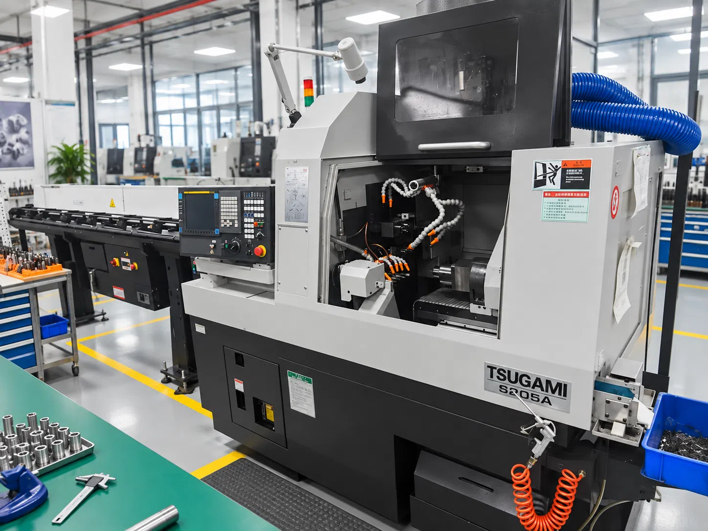
When the order requires a calibration record or traceability chain for a measuring instrument, state the required document and scope in the RFQ. A photograph of a CMM is not a substitute for that record.
Statistical process control [SPEC-04]
Statistical data, gauge R&R or process capability work needs a defined study, sample and measurement system. It is not inferred from one final inspection report.
Process Standards
From Drawing Review to Production Release
Send the controlled files. Include the 2D drawing, CAD model, revision, quantity and material condition.
Mark the decision features. Identify datums, GD&T, critical dimensions and the assembly function behind them.
Agree the inspection scope. Define method, sample, fixture state, report fields and the contractual or applicable ISO 14253-1 decision rule.
Machine and check the setup. Our machine shop uses process checks and tool-offset decisions against the approved manufacturing plan.
Release the first article. The defined first-article evidence is reviewed before the batch continues when that scope is ordered.
Inspect, record and ship. Final inspection is performed according to the released criteria and the associated record is kept as per the instructions.
Revision control before programming
The drawing revision and datum scheme were never fixed before programming: that is a common source of avoidable rework. This is one common cause of easily avoidable rework. We adopt the strategy of referencing 1 drawing and matching CAD model in the inspection brief.
First-article release scope
First article was requested, but the sampled features and release authority were unclear: that gap can hold a batch after machining. This can result in a batch hold after machining. We specify the ballooned characteristics, sample and approving authority before the release of the program.
Inputs that prevent late scope changes
| Input | Decision it controls | Late-change risk avoided |
|---|---|---|
| Released revision | Which geometry is accepted | Reprogramming against a different model |
| Functional datums | How the workpiece is aligned | Reports that do not match assembly |
| Critical feature list | Where measurement time is spent | Paying for low-value dimensions while missing risk |
| Fixture state | Free or constrained measurement | False agreement caused by support force |
| Report format | What evidence reaches incoming quality | Manual reformatting after shipment |
Metrology Inside Our Manufacturing Facility
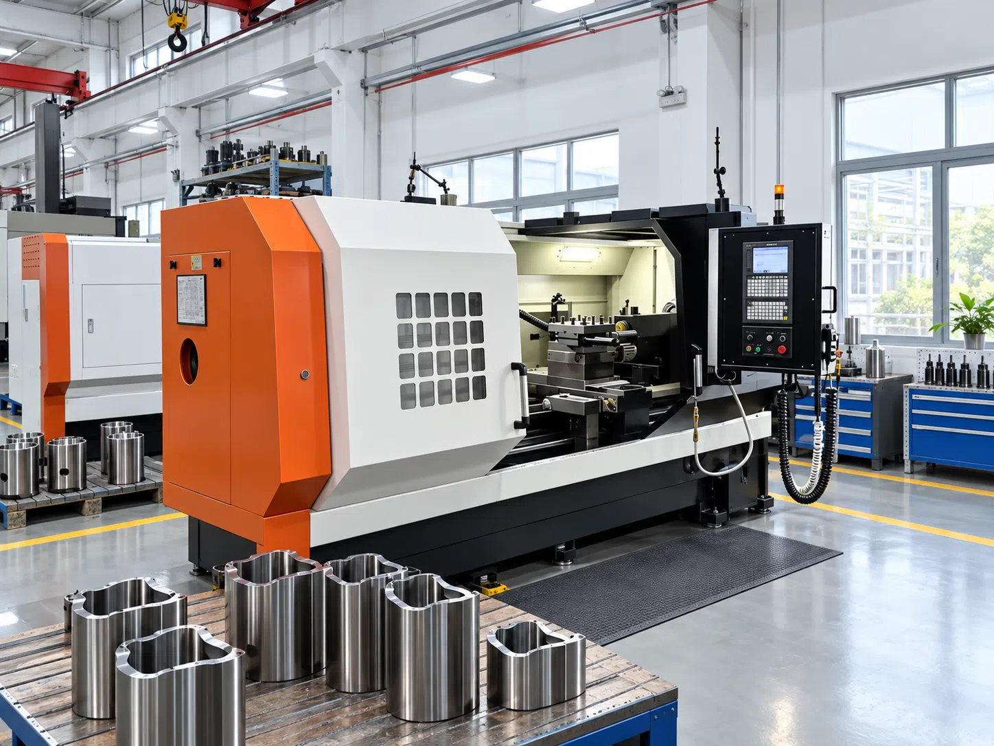
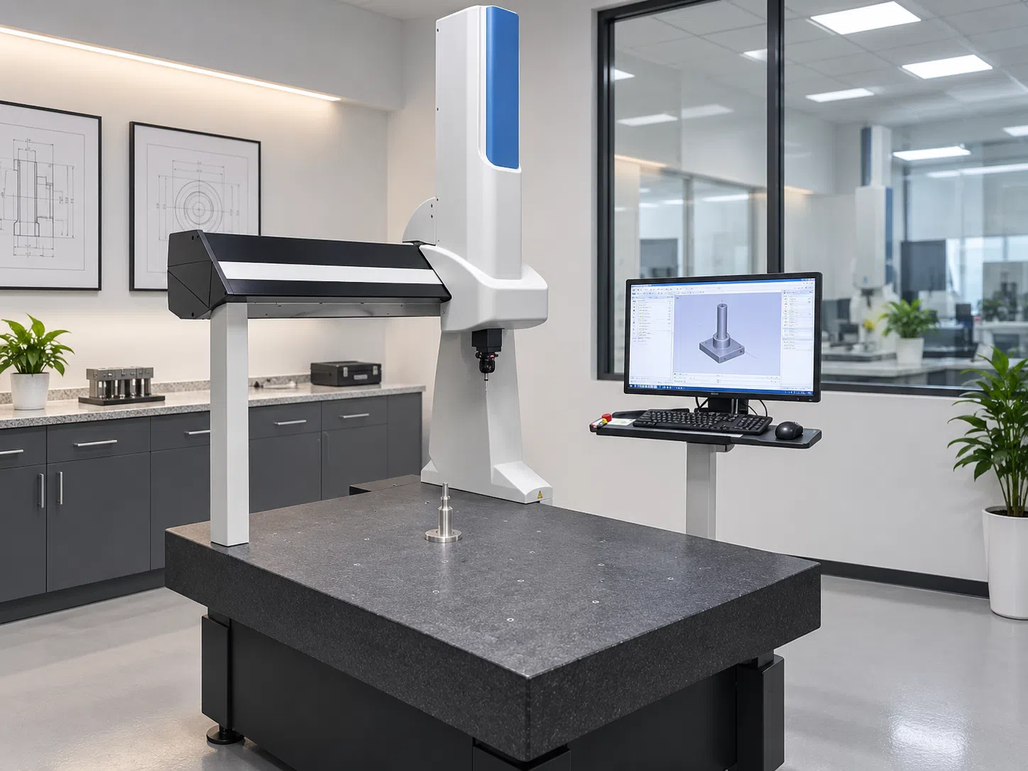
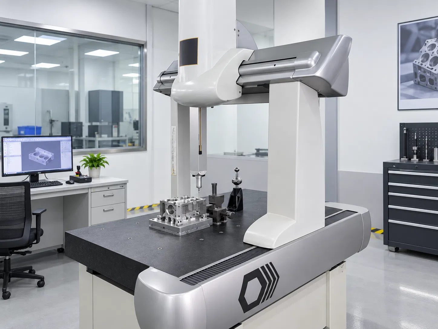
Shanghai Zhenling Hardware Co., Ltd. has produced made-to-print metal components since 2006. Our Jiashan site covers 8,000 square metres, including a 6,000-square-metre workshop with CNC machining and inspection linked in one manufacturing workflow. The equipment images document available hardware, while the NIST inspection-planning model keeps method suitability tied to the requirement rather than the machine photograph.

Production platform behind the measurement
-
Turning and milling
We produce flanges, rollers, valve bodies, plugs, bent-pipe components and other custom machined parts from drawings or samples.
-
Multi-axis work
Our machines include 3-axis, 4-axis and imported 5-axis machining centers for features that require coordinated setups.
-
Heavy industrial context
Our products are used in pressure-vessel, oil-gas separation and fluid-control equipment, where drawing revisions and dimensional records are very important to assembly.
Measurement Limits and Alternative Paths
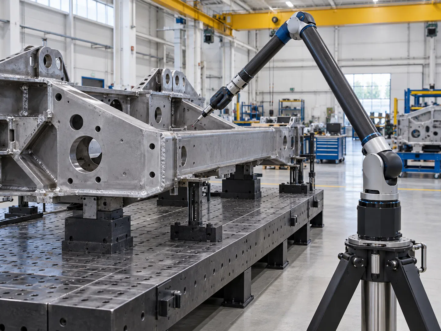
Not all characteristics warrant a CMM inspection. For a hidden bore or a large assembly, a fixed bridge CMM can be the wrong choice. The NIST inspection-planning model treats equipment selection as a requirements decision, so we identify the drawing requirement and confirm the functional check, tool or outside service.
Situation
Why CMM alone works against you
Better path
Situation
Simple accessible diameter during production
Why CMM alone works against you
Programming can add time without improving the process decision.
Better path
Use the right calibrated micrometer, bore gage or functional gauge.
Situation
Fine edge or low-contact surface
Why CMM alone works against you
A touch probe can influence or miss the intended boundary.
Better path
Evaluate optical, vision or non-contact inspection.
Situation
Hidden internal geometry
Why CMM alone works against you
Probe access may not reach the feature.
Better path
Review CT scanning, sectioning or a functional test through an agreed route.
Situation
Large on-site assembly
Why CMM alone works against you
The part may not suit a fixed bridge machine envelope.
Better path
Scope portable CMM, tracker or on-site measurement services.
Situation
Material identity or internal flaw
Why CMM alone works against you
Dimensional metrology does not answer chemistry or internal-defect questions.
Better path
Specify material tests or nondestructive testing separately.
CNC Metrology Engineering Tools
Tolerance Limit Calculator
Calculate precise upper and lower limits based on standard engineering fits and geometric dimensions for machined components.
Launch CalculatorInspection Method Selector
Determine the optimal measurement technique—from CMM to optical vision—based on feature accessibility and tolerance bands.
Launch SelectorInspection Scope Builder
Define AQL sampling plans and critical-to-quality (CTQ) reporting requirements before releasing drawings to production.
Launch BuilderCNC Metrology FAQs
Submission of a 2D drawing, 3D CAD model, drawing revision, datum scheme, GD&T callouts, critical features list, quantity, fixture condition, sample plan, report format and acceptance context will allow us to provide an accurate quote of the inspection services, as opposed to an estimate.
Results can be impacted by several factors including part temperature, cleanliness, datum simulation, fixture force, probe configuration, point strategy, software construction and rounding. One factor by itself does not prove that either result is wrong. Consider the method, uncertainty, and context and compare the number.
Ask for variable data when your quality team needs to diagnose how a derived position result was formed. ASME Y14.45-2021 distinguishes variable measurement data from attribute status, so the requested output should be stated before programming.
No. A first-piece check can support a setup decision, while first-article inspection follows a defined characteristic list, sample and report used for release; first-article inspection can be defined before batch release.
Use it when the contract or feature risk justifies checking every defined part or characteristic. It must be specified if the scope of 100% applies to the features, the part or both, because each scope has different CMM measurement and reporting burden.
In the request for quotation (RFQ), specify the required accreditation, governing standard and the purpose of the report. We confirm the applicable in-house or external inspection route in writing before quotation, without treating a machine photo as accreditation evidence.
Specify the customer standard, drawing revision, quality assurance records required, and the release authority. We will review that specification prior to quoting whereas a general assumption that a CMM services package will fulfill a regulated order will not be made.
Measurement data and a CAD model can support reverse engineering, but the deliverable, datum logic, point density and ownership of the design must be defined first. A scan or point cloud is not automatically a production drawing.
For complex jobs, the engineer-reviewed quotation is returned within 48–72 hours on business days. Send the critical-feature list and report request with the drawing to avoid a second scoping cycle.



