

Drawing-to-part programming and manufacturing
CNC Programming for Custom Machined Parts
CNC programming uses approved geometry and manufacturing requirements to create machine instructions and setup data and a defined path to inspection. Zhenling links that work to custom machining, so the programming talk begins with your drawing and ends with a confirmed manufacturing handoff.
Quote response
2–3 working days
Quotes are returned within 2–3 working days on business days, reviewed by an engineer.
Accepted files
7 accepted file extensions
We work from STEP, STP, IGS, IGES, PDF, DWG and DXF files.
Confidential review
NDA on request
Your drawings are handled as confidential; an NDA is available on request before file review.
Manufacturing context at a glance
Programming Inputs and Machining Scope
A key risk at this stage is assuming factory scale answers the release question. The company was founded in 2006 and its 8,000 m² factory and listed machine families establish manufacturing context; the project files still determine fit, and these supplier-specific figures come from the Zhenling company profile while ISO 16090-1:2022 is cited only for machine-safety context, not as validation of factory capacity.
2006
Established manufacturer
Shanghai Zhenling Hardware Co., Ltd. manufactures non-standard metal components from customer drawings or samples.
8,000 m²
Jiashan factory
The factory covers 8,000 square metres, including a 6,000-square-metre workshop in Zhejiang Province.
3–5 axes
Machining-centre range
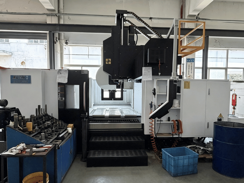
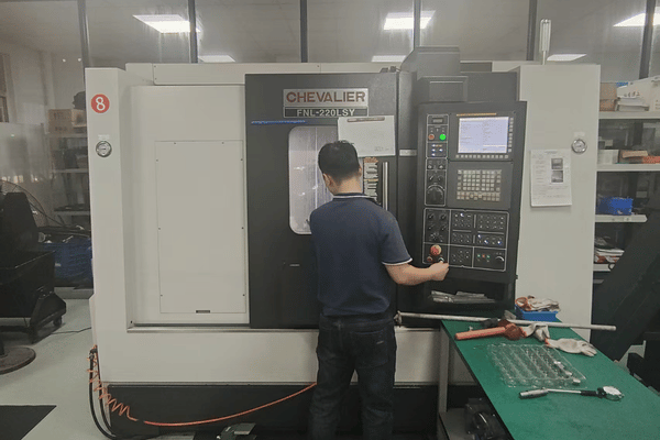
The equipment base includes three-axis and four-axis machining centers, and imported five-axis machining centers.
6 named process
Metalworking equipment
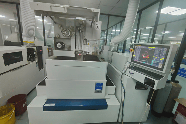
CNC turning, milling, grinding, boring, radial drilling and wire-cut EDM support the programming-to-part route.
1 piece
Prototype entry point
Production of prototypes starts with a one-piece order, with the feasibility and the scope confirmed from the released files.
EXW / FOB
Trade terms
We ship EXW and FOB; other Incoterms can be reviewed on request.
More than code generation
CNC Programming Capabilities
The exact process depends on geometry, material, stock, machine, controller, tooling, workholding, tolerance, and inspection. Our goal is to show these dependencies before the first move of production.
01
Drawing and model review
Project review identifies the controlling revision and units, datums, critical features, and conflicts between the drawing and model.
02
Operation planning
Features are grouped into machining operations with a setup sequence that considers access, stock removal, and stable referencing.
03
CAD/CAM toolpaths
CAM toolpaths transform the planned operations into controlled cutter motion while retaining the geometry and process assumptions for review.
04
Bounded manual edits
Manual code review can support controlled changes that are clear, but the output of the editing still goes through the same revision and verification process.
05
Postprocessing
The target machine and controller determine the post. The posted output should be reviewed before release.
06
Setup definition
The handoff identifies stock, fixtures, work coordinates, tools and the source of offset values used at the machine.
07
Program verification
Toolpath and posted-code review focus on defined digital risks, including travel, approach, retract, holder and fixture conflicts.
08
Prove-out feedback
Controlled first-run observations and inspection findings remain inputs to released setup and program-revision decisions.
Compatibility is specific. A useful program belongs to a named machine, controller, post revision, setup and tool state; generic CAM output is not a complete production handoff.
A CAM file is not a release
A CAM file is not a released machine program until the target machine, controller, post, tool library, fixture, stock and work coordinates are identified.
A correct toolpath can still fail at setup
A correct toolpath paired with the wrong work offset can cut the right geometry in the wrong position. Digital motion is not a substitute for physical offset control.
Program revision and drawing revision must stay linked
When the NC file, setup sheet and inspection plan are not associated with the same job identity, program and drawing revisions may occur out of phase. These records are not interchangeable.
Terminology tied to the manufacturing handoff
Programming Methods, CAD/CAM and Shop-Floor Context
CNC programming is the process of converting design intent into controlled instructions for computer numerical control equipment. Programming languages may include G-code and other machine code, while practical machine programming also covers the setup, cutting tool, workpiece and verification context.
Manual and conversational programming
This type of CNC programming fits bounded operations when the CNC programmer and machine operator can verify each assumption. Conversational programming can simplify basic CNC input at a supported control, while complex modeling usually moves into a CAM program. Practical CNC programming involves the same revision, setup and verification duties whichever input method is used.
CAD and CAM workflow
Computer-aided design creates the CAD model or blueprint definition; computer-aided manufacturing generates the tool path from selected CAD data. CAD and CAM remain separate responsibilities even when CAD and CAM software share one interface.
CAM programming controls
CAM software helps define cutting tool motion, spindle speed, feed rate and operation order. A CAM program requires the target CNC machine, machine type, post, stock and work coordinate system before shop-floor release.
Service and training intent
A CNC programming service resolves a production handoff, while beginner tutorials, online courses and pages that teach users to learn CNC programming address a training need. Training resources can build an understanding of CNC; this page stays with the part, program and release package.
Software Names Do Not Prove Compatibility
Searching for the best CNC programming software often surfaces CAD software and CAM software brands such as Autodesk or Mastercam. CNC machine compatibility depends on the CAD source, CAM output, post revision and actual control configuration, rather than a brand name alone.
| Context | What CNC machines use | Release question |
|---|---|---|
| CNC machine programming | Machine code produced manually, through conversational input or by CAM | Does the coding match the named controller and enabled options? |
| Programming CNC machines | A work coordinate system, tool offsets, stock and CNC machine setup data around the NC file | Does the physical workpiece match the programmed origin and restraint? |
| CNC lathes and machining centres | Different axis, cycle, spindle and tool-change conventions | Has the post output been checked for the exact CNC machine? |
| CNC routers and other machine tools | Machine-specific travel, workholding and control behaviour | Is this machine tool actually within the quoted manufacturing route? |
| Automation and repeat production | Controlled revisions and repeatable setup inputs | Did first-part feedback close into the released CNC process? |
This trade-off is speed of input versus visibility of assumptions.
CAD defines geometry, CAM plans cutter motion, the post creates CNC machine-specific output, and physical setup plus inspection determine whether the programmed intent became the required part.
Material data affects the route
Material Inputs That Change the Program
While a material grade is a starting point, it is not a universal cutting recipe. The review should include condition, hardness, stock form, heat treatment, tool access, chip behavior, and inspection requirements; because conventional G-code does not carry complete production-state feedback, material condition stays in the controlled job package rather than being inferred from the NC file.
01
Carbon and structural steels
20#, 45#, Q235A and Q345D may call for different stock, heat-treatment and hardness assumptions. Specify the grade and delivery condition instead of sending “steel” as the full specification.
02
Alloy and bearing steels
12CrMoV, GCr15, 25CrMo and 42CrMo make hardness, heat treatment, stock allowance and tool access especially important to process planning.
03
Stainless steels
Chip control, heat concentration, feature access and the surface state are the focus when we review 303, 304, 304L, 316, 316L, 321.
04
Special alloys
C276, 904L and nickel-based alloys require project-specific decisions about material condition, stable workholding, tooling and inspection timing.
05
Aluminium alloys
Identify the specific alloy, temper, stock form as well as the cosmetic requirement to ensure toolpath and workholding are appropriate for the final part.
06
Drawing-controlled condition
If the final treatment or hardness will dictate machinability, then include the required state as well as the inspection phase on the released drawing.
Plan beyond the cutting cycle
Downstream Process Inputs
Heat treatment, welding, grinding and surface treatment can change stock allowance, datum access, distortion risk and the inspection state. State these conditions on the print or RFQ before the program route is locked; because conventional G-code does not carry complete production-state feedback, downstream-treatment state remains in the drawing, process and inspection records rather than the NC file alone.
| Downstream input | Programming effect | Release check |
|---|---|---|
| Heat treatment | May require intermediate stock and a separate finishing operation. | Name the treatment, target hardness and inspection stage. |
| Grinding | Changes machining allowance and which features remain for final size control. | Identify ground surfaces and final datum relationships. |
| Welding | Can alter access, restraint and sequence when machined features locate to a fabricated assembly. | Define pre-weld and post-weld machining states. |
| Coating or plating | Build thickness can affect fits, threads, bores and masked areas. | State dimensions before or after coating and mark masking. |
| Cosmetic finish | Visible faces may change clamping, handling and final-pass choices. | Mark appearance-critical surfaces on the drawing. |
| Assembly | Mating interfaces may drive datum choice, sequencing and functional checks. | Provide the interface requirement or mating-part context. |
Control units, revisions and physical state
Program Units and Release Controls
A release package should answer which source controls, what changed and which machine state the program expects. These checks help organize the handoff, but do not replace engineering approval and do not substantiate the physical process on their own; NIST’s production-feedback boundary is why physical state is recorded separately from the NC file.
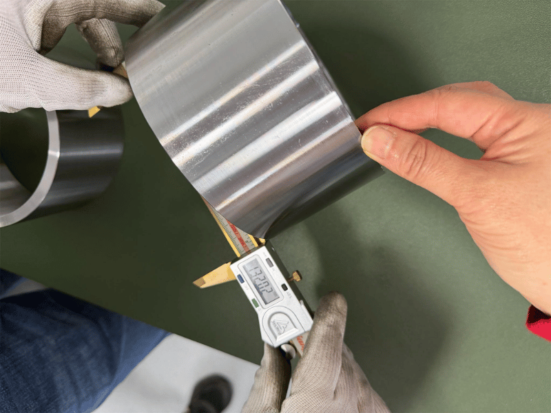
Authority dataset
- Drawing and model revision
- Authoritative source when files disagree
- Approval and change record
Program identity
- CAM and NC revision link
- Machine, controller and post revision
- Units and coordinate-frame definition
Setup identity
- Stock and workholding definition
- Tool list and offset source
- Current machine and fixture state
Acceptance identity
- Inspection revision
- Critical-characteristic list
- First-part feedback and approval
Unit Conversion Examples
The examples below are neutral conversion data for assessing unit consistency. They are not Zhenling tolerance offers or default acceptance bounds.
| Millimetres | Inches | Release use |
|---|---|---|
| 0.01 mm | 0.000394 in | Confirm the converted value and rounding rule. |
| 0.025 mm | 0.000984 in | Keep the authority unit visible beside derived values. |
| 0.05 mm | 0.001969 in | Do not infer an inch value from display precision alone. |
| 0.10 mm | 0.003937 in | Bind setup and inspection files to the same unit state. |
| 0.25 mm | 0.009843 in | Resolve mixed-unit stock, tool and offset data before release. |
| 0.50 mm | 0.019685 in | Record who approved any rounded conversion. |
RFQ SYS.
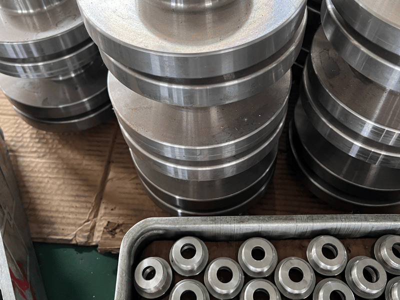
Commercial terms linked to scope
Pricing and Lead-Time Commitments
Program and machine costs are dictated by the geometry of the part, the number of setups required, access to each axis, material, tolerancing, inspection, the extent of processing required, and the number of parts required. A written quotation links these factors to the files and revisions reviewed by engineering.
Prototype
7–15 business days
Prototype parts ship in 7–15 business days after drawing approval.
Small batch
7–15 business days
Small-batch orders ship in 7–15 business days after drawing approval.
Production
25–35 business days
Production runs are scheduled at 25–35 business days after sample approval, confirmed with the quotation.
Payment
50% / balance
Payment is 50% deposit with the balance before shipment by wire transfer.
What Moves the Quotation
| Driver | Why it matters | Useful RFQ input |
|---|---|---|
| Geometry and access | Deep, enclosed or multi-directional features can add setups, tools or axis requirements. | Send the 3D model with a dimensioned drawing. |
| Tolerance and inspection | Critical relationships change process control and reporting work. | Mark critical features, datums and required records. |
| Material and condition | Grade, hardness and stock form affect the process route. | Name the exact specification and delivery condition. |
| Quantity and release stage | A prototype, sample approval and repeat run use different planning assumptions. | State prototype quantity, production quantity and approval sequence. |
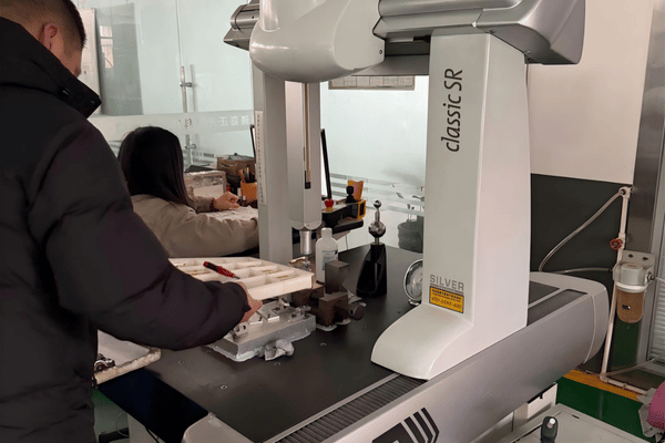
- 1. Authority identityDrawing, model, revision and approval state.
- 2. Derived-file traceabilityCAD/CAM, posted NC, setup, and inspection records for one identified job.
- 3. Process planOperations, setups, datums, stock, and the sequence of secondary processes.
- 4. Machine matchNamed machine, controller and post revision.
- 5. Current physical stateCurrent status of tooling, machine, workholding, and measurement.
- 6. Digital reviewToolpath, posted code, limits, movements, retracts and modeled collisions.
- 7. Controlled prove-outFirst-run controls applied to the physical setup and offset state.
- 8. Inspection closeoutFirst-part results, corrections, approvals, and released repeat-run information.
Buyer-facing engineering control
Program Verification and Inspection Handoff
The Program Release Proof Spine is designed to help engineering and purchasing departments to identify the project documentation that is required. It keeps digital checks connected to the actual machine, setup and inspection result without treating a checklist as a certification or automated digital thread.
NIST documents the production-feedback gap in conventional CAM/CNC flows. The risk persists because a digital program is not a substitute for the current physical state; the release framework therefore separates simulation, prove-out and inspection decisions, while ISO 10791-7:2020 provides a physical cutting-test reference.
The key boundary: configuration alignment is necessary, but it does not prove current manufacturing capability because conventional G-code does not carry complete production-state feedback. Machine condition, offsets, workholding and measurement evidence remain separate controls.
| Review layer | Can reveal | Does not establish alone |
|---|---|---|
| CAM toolpath review | Planned geometry, operation order and programmed cutter motion | Correct post output or current shop-floor setup |
| Posted-code verification | Machine-aware motion, limits and modeled fixture or holder conflicts | Actual offsets, clamp state, material behaviour or inspection conformity |
| Controlled prove-out | Behaviour of the program on the identified physical setup | Conformity of every critical feature without measurement |
| First-part inspection | Measured results against the released definition | Future-run control unless revisions and repeat-production inputs are closed |
“Simulation can miss physical reality when tool, holder, fixture or offset data is stale. The release framework therefore keeps digital review, controlled prove-out and first-part inspection as separate release decisions.”
ISO 10791-7:2020 uses finished test pieces to assess machining-centre cutting accuracy, reinforcing the distinction between digital review and physical cutting evidence.
Six-step project route
From Drawing Review to Machined Part
Responsibility boundary: Zhenling is responsible for the manufacturing scope and acceptance inputs agreed in the quotation. Undisclosed design assumptions cannot be converted into reliable programming requirements after release; NIMS lists machine verification, physical test cutting and quality control as separate tasks, but that structure does not certify this project workflow.
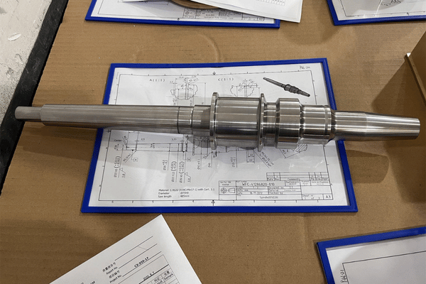
01 / STEP
Send the project inputs.
Send the drawing or model, quantity, material, application, target date and known acceptance criteria.
02 / STEP
Resolve the definition.
The project review covers geometry, revisions, units, datums, tolerances, finishes and missing release inputs.
03 / STEP
Confirm the route.
Your quotation states the manufacturing scope, the timeframe, the commercial terms and the files reviewed.
04 / STEP
Prepare the package.
Project planning aligns the machine route with programming, setup, post processing and verification.
05 / STEP
Machine and inspect.
Controlled machining and agreed inspection test the released program against the physical part.
06 / STEP
Close the revision.
Corrections and first-part feedback remain release inputs before repeat-production information is released.
Program Release Readiness Checklist
Mark which authority, machine, setup, verification and inspection inputs are already controlled.
Assess the release package →Confidential file review
An NDA is available on request before file review when the project contains sensitive product or process information.
Start a protected review →
Programming connected to production
Zhenling Manufacturing Context
Headquartered in China with a factory in Jiashan County, Zhejiang Province, Zhenling focuses on customised non-standard metal components. The team works from customer drawings or samples across components such as machine assemblies, flanges, rollers, bent pipes, valve bodies, plugs and other made-to-print parts.
Turning and milling
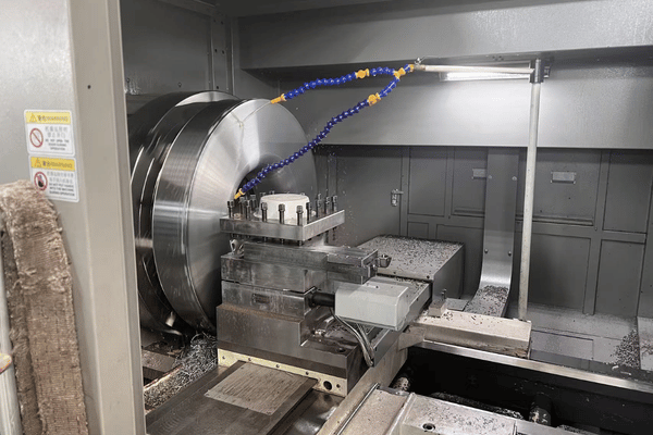
CNC lathes, CNC milling machines and multi-axis machining centres support rotational, prismatic and multi-face parts.
Hole and bore operations
CNC boring and radial drilling equipment extend the available process route for holes, bores and large-part access.
Grinding and EDM
CNC grinding and wire-cut EDM add process options when the drawing calls for features suited to those methods.
Fabrication context
Shearing, plate rolling, pressing and welding equipment support projects that combine fabricated and machined features.
Explore the programming knowledge base
CNC Programming Reference Modules
Program language
CNC G-Code Basics
For posted NC programs, read program blocks, modal states and controller-specific code context. Without treating code as controller independent, refer to the structure behind the posted NC program.
Explore CNC G-Code Basics
Machine reference frames
CNC Coordinate Systems
Prior to release, connect machine, work, tool, and drawing-reference frames. The guide explains why coordinate and offset context must travel with the setup.
Explore CNC Coordinate SystemsResolve the input before code release
When CNC Programming Alone Is Not Enough
The mistake is checking only the visible cutting path. Rapids, retracts and approach moves can create risk before cutting begins, which is why shop-floor verification also checks the first moves.
| Situation | Why it works against the project | Better next step |
|---|---|---|
| Incomplete drawing | Missing dimensions, material, finish or acceptance criteria leave the programmer to guess design intent. | Complete critical inputs and name the authority dataset before programming. |
| Unknown controller or post revision | Code syntax and machine behaviour cannot be assumed from a generic CAM file. | Identify the exact machine, controller and approved post combination. |
| Undefined workholding | A toolpath cannot compensate for an unstable datum or unverified restraint strategy. | Establish stock, datum access, fixture state and clamp sequence before release. |
| Simulation without physical evidence | A digital model may not include current offsets, tool stickout, fixture changes, deflection or material movement. | Use controlled prove-out and first-part inspection as separate release controls. |
Digital Engineering Resources
CNC Programming Engineering Tools
CNC Programming Scope Selector
Define project boundaries and manufacturing inputs before writing code.
Launch Tool
Machine–Post Compatibility Checker
Verify CAM output against specific machine controllers and physical setups.
Launch Tool
Program Release Readiness Checklist
Audit your release package for authority, setup, and inspection completeness.
Launch Tool
Prepare a controlled manufacturing handoff
Send Your Drawing for Programming and Machining Review
Share the governing files, quantity, material, application and acceptance requirements. An engineer will review the manufacturing route and return a quotation within 2–3 working days on business days.
Review Your CNC Project-
REQ-01
STEP, STP, IGS, IGES, PDF, DWG or DXF
-
REQ-02
Drawing/model revision and authority source
-
REQ-03
Material, condition and quantity
-
REQ-04
Critical tolerances and datum scheme
-
REQ-05
Secondary processes and inspected state
-
REQ-06
Target date and sample-approval plan
-
REQ-07
Machine/controller context when relevant
-
REQ-08
Required setup and inspection records
Technical and commercial questions
CNC Programming FAQs
The process converts approved geometry and manufacturing requirements into machine instructions, setup information and a verification route. It retains a connection to the drawing revision, machine context, and inspection outcome.
No, g-code is a type of machine instruction. CNC programming covers process planning, toolpath creation, postprocessing, setup definition, verification, and revision control.
In some cases, manual programming can work. This programming approach can be used for well-understood or constrained machining operations, or programming edits. Complex geometry and multi-axis motion usually benefit from CAD/CAM, but both routes require machine-specific review.
CAM applies machining operations and toolpaths to approved geometry, then a postprocessor generates output for a given controller. This output must also be verified against the target machine and setup.
The post interprets CAM intent into syntax and motion that are appropriate for a given machine/control context. Incorrect interpretation can change commands, cycles, or assumptions, and even axes, even though the CAM toolpath looks correct.
Include the governing drawing or model, revision, units, material, quantity, stock or sample, tolerances, finishes, and the inspection requirements. Machine, controller, post, tooling and workholding inputs are also needed before release.
The setup links drawing datums to the planned work coordinate, fixture and offset source, then verifies that the physical setup matches that definition. The related coordinate-system guide explains the reference frames in more depth.
No. Simulation can reveal modeled digital risks, while actual conformity still depends on the physical machine, tooling, offsets, workholding, material behaviour, measurement process and inspection result.
We work from STEP, STP, IGS, IGES, PDF, DWG and DXF files. Pair a three-dimensional model with a dimensioned drawing when both are available, and identify which source controls if they conflict.
Yes. Prototype orders start from 1 piece, subject to drawing review, material availability, process feasibility and the scope confirmed in the quotation.
Prototype and small-batch parts ship in 7–15 business days after drawing approval. Production runs are scheduled at 25–35 business days after sample approval, confirmed with the quotation.
Your drawings are handled as confidential, and an NDA is available on request before file review. Use the project enquiry to identify any additional data-handling requirements before transfer.



