
Thread and hole
- Thread series, nominal diameter, pitch or TPI, and class.
- Internal-thread depth and blind or through-hole condition.
- Hole count, location and available edge distance.
- Cutting tap, forming tap or another specified process.

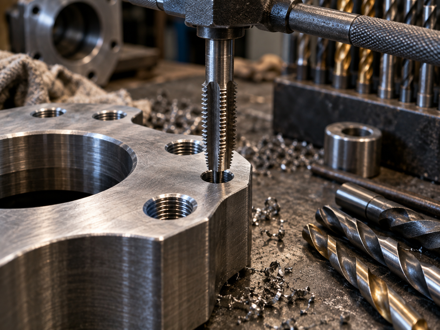
Use this tap drill chart to find a cutting-tap starting drill size, compare metric and inch callouts, and include the necessary details in a custom tapped-part drawing. The tables below stay visible when JavaScript is unavailable.
These are cutting-tap reference sizes for common threads. A forming tap, blind hole, material-specific process, or finished-thread requirement needs its own review.
Non-standard metal components made to client inputs.
CNC turning, milling, wire EDM, grinding and boring.
Steels, stainless steels, nickel-based alloys and aluminum alloys.
Start with the thread’s nominal diameter and pitch, then read the drill column as a cutting-tap reference for metric threads. The drill and tap chart filters both the metric and the Unified tables below.
| Thread | Pitch | Cutting-tap drill | Decimal in | Series |
|---|---|---|---|---|
| M3 × 0.5 | 0.5 mm | 2.5 mm | 0.0984 | Coarse |
| M4 × 0.7 | 0.7 mm | 3.3 mm | 0.1299 | Coarse |
| M5 × 0.8 | 0.8 mm | 4.2 mm | 0.1654 | Coarse |
| M6 × 1 | 1.0 mm | 5.00 mm | 0.1969 | Coarse |
| M6 × 0.75 | 0.75 mm | 5.25 mm | 0.2067 | Fine |
| M8 × 1.25 | 1.25 mm | 6.75 mm / 17/64 in | 0.2657 | Coarse |
| M8 × 1 | 1.0 mm | 7.00 mm | 0.2756 | Fine |
| M10 × 1.5 | 1.5 mm | 8.50 mm | 0.3346 | Coarse |
| M10 × 1.25 | 1.25 mm | 8.75 mm | 0.3445 | Fine |
The values and inch equivalents are transcribed from the 6G Tools metric chart. In a machine shop, a wrong M8 pitch can change the production pilot from 6.75 mm at M8 × 1.25 to 7.00 mm at M8 × 1; these drill sizes are not interchangeable, so match the exact row to the available drill bit.
Unified threads are threads per inch (TPI), and the drill can be a numbered, lettered or fractional bit. This drill size chart connects screw size and TPI to the pilot diameter.
| Thread Series | Cutting-tap drill | Decimal in | Approx. mm |
|---|---|---|---|
| 1/4-20 UNC | #7 | 0.2010 | 5.11 |
| 5/16-18 UNC | F | 0.2570 | 6.53 |
| 5/16-24 UNF | I | 0.2720 | 6.91 |
| 3/8-16 UNC | 5/16 in | 0.3125 | 7.94 |
| 3/8-24 UNF | Q | 0.3320 | 8.43 |
| 7/16-14 UNC | U | 0.3680 | 9.35 |
| 7/16-20 UNF | 25/64 in | 0.3906 | 9.92 |
| 1/2-13 UNC | 27/64 in | 0.4219 | 10.72 |
| 1/2-20 UNF | 29/64 in | 0.4531 | 11.51 |
A tap drill prepares the hole that will receive internal threads; a clearance hole lets a fastener pass through another part. The two hole types serve different functions in the assembly.
The pilot diameter is chosen for the tap type and planned engagement of thread. A wrong choice risks damage to internal threads.
The passing part needs a clearance fit; it does not use the tapped-hole row automatically.
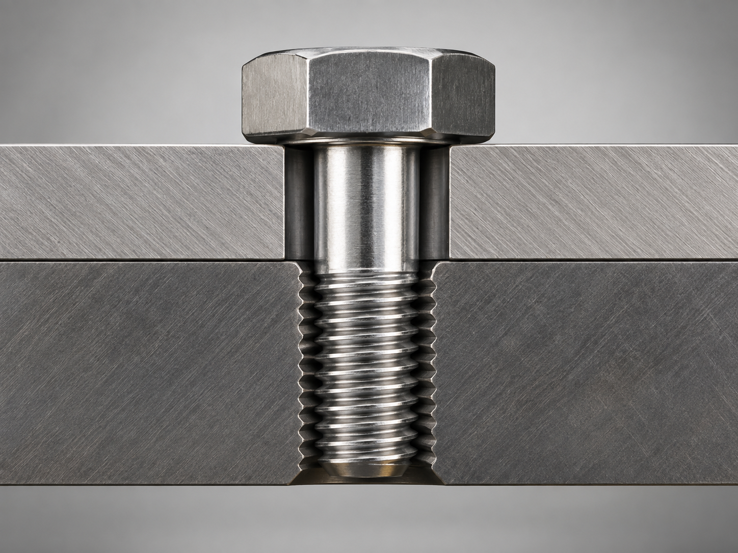
Conceptual cross-section, not to scale. Select clearance-hole fit separately; ISO 273 distinguishes fine, medium and coarse clearance-hole series.
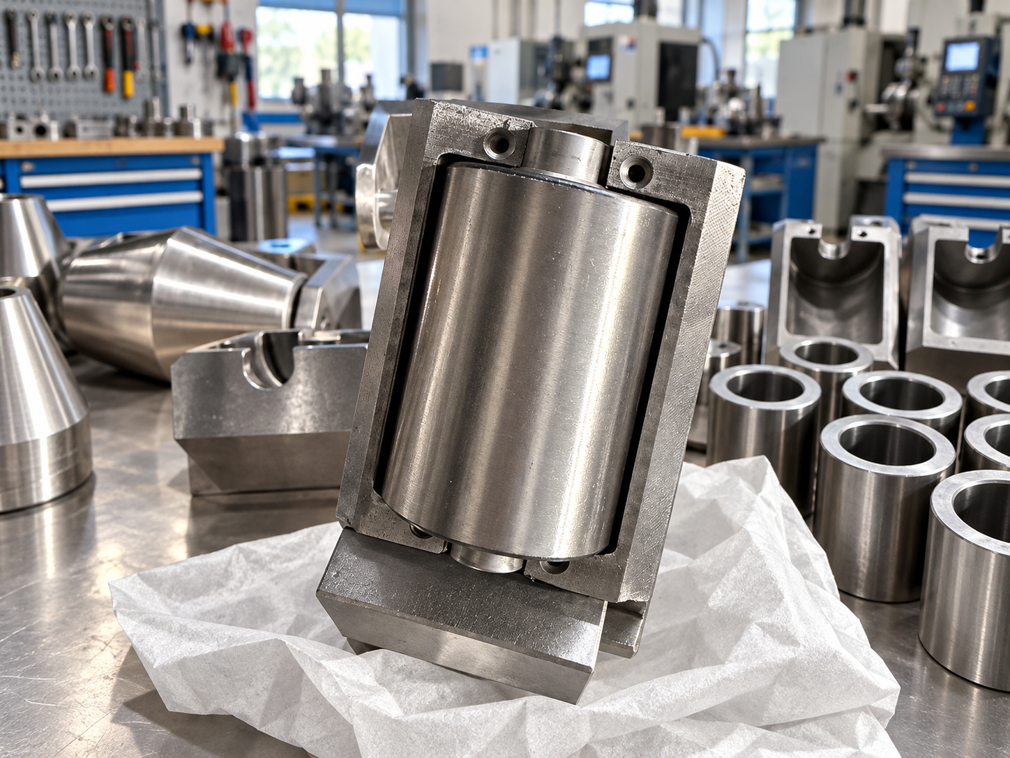
Cutting and forming taps displace metal differently. Use a process-specific drill recommendation for a forming tap.
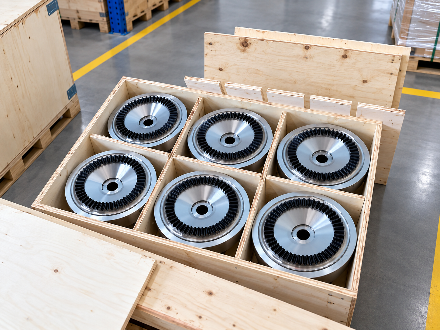
Through and blind holes change chip evacuation and usable thread depth. Include the hole condition in the part drawing.
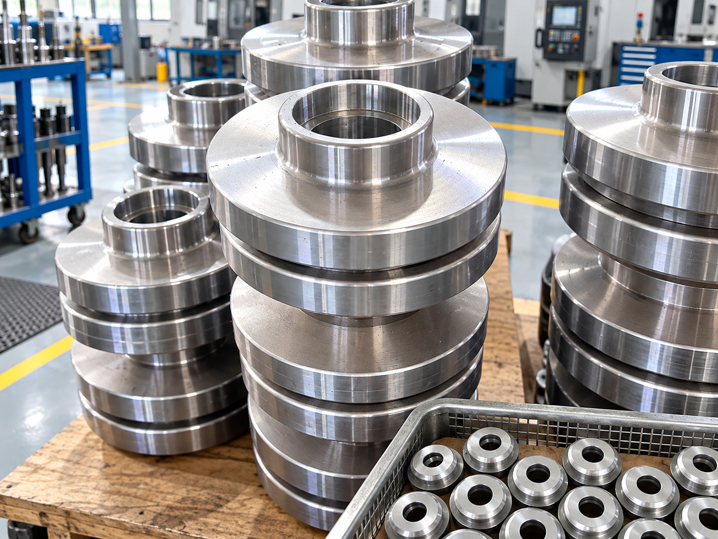
Nominal drill size in and of itself does not establish an accepted thread. Identify the class and inspection criteria in the drawing or the specification that is referenced.
Shanghai Zhenling Hardware Co., Ltd. was established in 2006, with our factory in Jiashan County, Zhejiang. Our input route is simple: We machine non-standard parts from client drawings or samples.
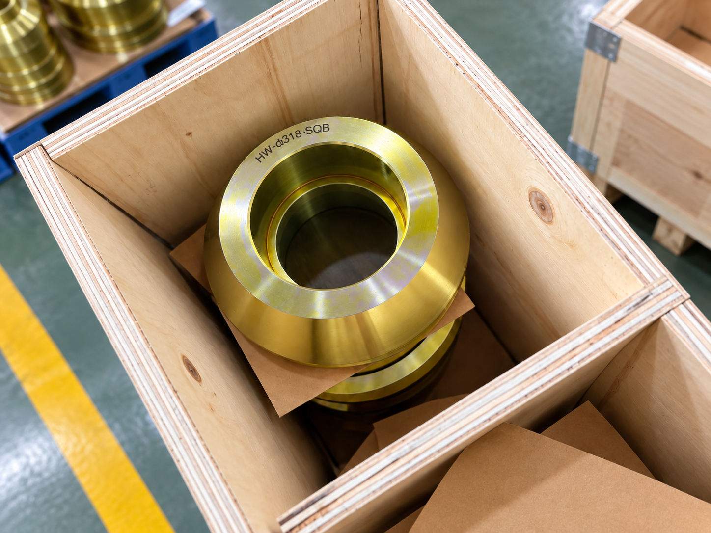
For a custom threaded component, price follows material, geometry, thread specification, quantity and finishing.
Send the part drawing for a project-specific reviewA clear thread callout changes a reference drill size into a reviewable request. Include any external specification that provides acceptance criteria, even if those criteria are incorporated by reference.
Read the 1.0 mm pitch row: the listed cutting-tap drill is 5.00 mm (0.1969 in). Review material, thread class and hole depth before specifying the production process.
The cited row lists 6.75 mm (17/64 in; 0.2657 in decimal). The chart value is a starting reference for a cutting tap, not a universal forming-tap diameter.
Find 20 TPI in the UNC table: the listed drill is #7, 0.2010 in (5.11 mm). Confirm the Unified class and acceptance criteria separately.
A wrong pitch, tap type or inspection assumption can invalidate an otherwise correct drill-chart lookup. Compare the example against the part drawing before production. Source rows: metric chart and UNC chart.
Distinguish tap-drill holes from bolt clearance holes; the wrong hole type risks assembly mismatch.
State a cutting-tap assumption beside any chart row; a forming tap requires its own pilot-hole selection.
Preserve exact M8 values when comparing a 6.75 mm source row with another drill series.
Explain that a nominal drill value does not set finished-thread acceptance or inspection.
Give a drawing checklist for blind/through geometry, engagement, material and acceptance method.
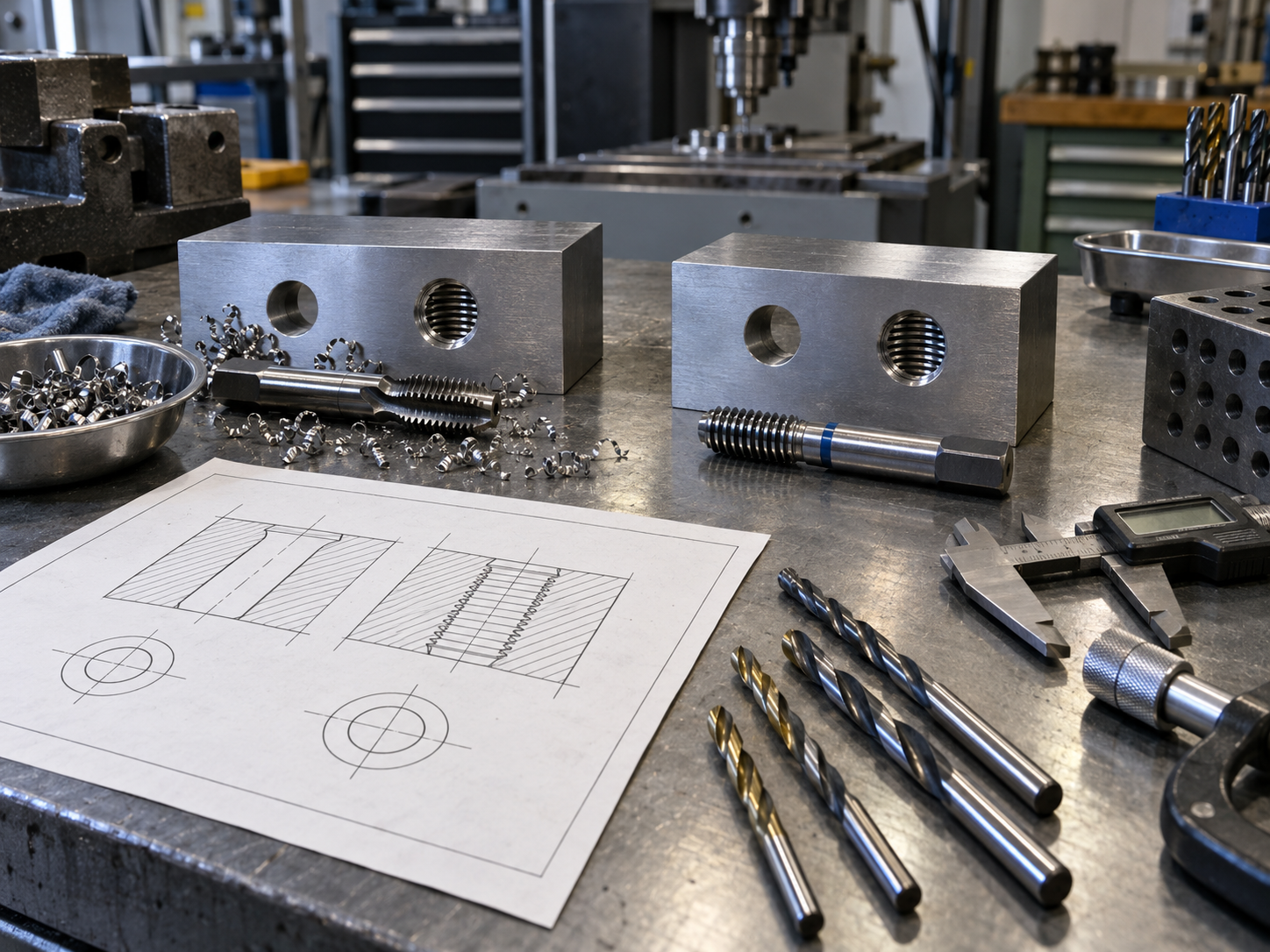
A chart row is not always the right production drill for a deep blind hole. Cutting Tool Engineering’s deep-hole guide explains why chip evacuation and tool choice become important as thread depth grows.
Convert drill bit dimensions between metric and imperial standard units instantly. Ensure accurate tooling specifications for international engineering drawings.
Open Drill Diameter Unit ConverterCalculate precise pilot hole sizes by subtracting the thread pitch from the nominal metric diameter. A reliable reference for CNC pre-machining preparation.
Open Pilot Estimate ToolVerify standard engineering thread callout formats to avoid manufacturing discrepancies. Ensure your CNC machining requests meet standard drafting specifications.
Open Thread Callout ChecklistThe cited metric chart lists 5.00 mm for the cutting-tap starting hole.
The source row lists 6.75 mm, also shown as 17/64 in.
The cited inch chart is #7, which is approximately 0.2010 in or 5.11 mm.
No. One prepares an internally threaded part; the other allows the fastener to pass through a mating part.
Forming taps require a different method of pilot-hole selection. Check the tap manufacturer’s recommendation for the material and target thread.
No. Guhring states that a chart’s single-size value is approximate and gives a reason to explain why the engagement can change with application conditions.
Reference tables can have different preferred bit series, rounding, and engagement assumptions. Follow the cited row and examine the actual tap and the part needs.
Indicate thread designation, class or tolerance, location, depth, material, and applicable inspection criteria or referenced specification.
Send the drawing or sample details through the part-review form, along with the thread and material requirements.



