

CNC programming reference for manufacturing teams
CNC G-Code Basics: Diagrams, Examples and Key Terms
The phrase g code cnc covers the address words that tell a numerical control how to interpret motion, coordinates, modes, offsets and cycles. This page presents a cross-referencing method designed to minimize the amount of reading needed, a command-oriented source table, and verification chains that present an educational example separately from a production-level program.
Use boundary
This is an educational reference, not a machine setup, operating, lockout or safety procedure. Check the exact controller manual, machine configuration, postprocessor, active offsets and approved shop procedure before any live run.
Block: One program line containing commands and arguments·
Word: A letter address followed by a value or expression·
Modal state: A command state that remains active until its group changes·
Controller context: The control, machine type and options that give a code its exact meaning·
Block: One program line containing commands and arguments·
Word: A letter address followed by a value or expression·
Modal state: A command state that remains active until its group changes·
Controller context: The control, machine type and options that give a code its exact meaning·
G-Code in CNC at a Glance
G-code includes instructions for geometric and preparatory moves, while M-codes deal with machine functions, such as stopping the program or changing the coolant status. This breakdown aids in reading. However, the exact commands remain machine- and controller-dependent.
Movement and geometry
Motion words select rapid positioning, linear interpolation or an arc. Axis words such as X, Y and Z supply the programmed endpoint in the active coordinate and distance modes.
Coordinate state
Machine coordinates, work offsets and programmed positions are different layers. A line cannot be interpreted correctly until you know which work coordinate system and offsets are active.
Modal commands
Motion, plane, units, distance mode, compensation and canned-cycle state can persist across later blocks. The omitted word may still be active, which is why reading one isolated line can be misleading.
Machine functions
M-code behavior belongs to the named controller and machine configuration. Never assume that an M-code copied from a mill reference has the same effect on a lathe, router or another control.
Why this page is scoped
Unlike a universal code dictionary, this page treats a command as controller-scoped evidence. The risk comes from hidden state because the same visible word can be interpreted against different active conditions; the NIST publication NISTIR 6556 provides the interpreter-level baseline, whereas the right call for production is to confirm against the named controller manual.
Shared format, bounded interchangeability
ISO 6983-1:2009 addresses program format and definitions of address words. Its interchangeability objective is limited to numerically controlled machines of the same classification by type, process, function, size and accuracy, so a shared syntax does not erase controller scope.
PROGRAMMING ARCHITECTURE
Anatomy of a CNC Program Block
NISTIR 6556 and the LinuxCNC language overview define a program as words that are joined together to create blocks, or lines. In the simple block example below, each letter plays a particular role in assigning the following value.
Interactive reference: open the Program Block Decoder to label a single educational block without generating machine code.
Program Block Decoder System Active
N120 G01 X42.0 Y18.0 F250
N120
Optional sequence number used to identify the block.
G01
Linear motion at the programmed feed rate in the active motion group.
X42.0
X-axis endpoint interpreted through the active units, work offset and distance mode.
Y18.0
Y-axis endpoint under the same coordinate state.
F250
Feed-rate value interpreted through the control’s active feed mode and units.
Character check
The letter O and digit 0 can be confused in program text, as can lowercase l and digit 1. Use the controller’s accepted character set and a verified editor instead of resolving an ambiguous scan by sight.
Read state before values
- Identify the controller family, software version, machine type, and the installed options.
- Confirm the active motion, plane, units, distance, feed and compensation groups.
- Resolve the machine coordinate, work offset, tool length offset and cutter compensation.
- Read axis and feed words only after that state is known.
Core G-Code Groups and Modal State
A modal command remains active until it is replaced by another modal command in the same group. LinuxCNC states a restriction of “same block” for multiple G or M words within the same modal group. Consider that a named implementation rule rather than a guarantee that will always hold for all controls.
Why hidden state causes reading errors
Units mismatch
The same coordinate value has a different physical scale under G20 and G21. A copied block without its units line is incomplete evidence.
Distance mismatch
Under G90, X20 is an absolute endpoint in the active work system. Under G91, it is a 20-unit movement from the current programmed position.
Plane mismatch
Arc-centre words and circular direction depend on the selected plane. An arc example without G17, G18 or G19 context is not portable guidance.
Group
Active State
Replacement Rule
Motion
G00 rapid positioning
G01, G02 or G03 replaces the active motion state
Plane
G17 XY plane
G18 XZ or G19 YZ changes arc and compensation interpretation
Units
G21 metric input
G20 changes programmed values to inch input
Distance
G90 absolute positioning
G91 reads the next endpoint as an increment from the current position
Compensation
G40 cutter compensation off
G41 or G42 changes the compensated path side
Cycle
G80 canned cycle cancelled
G81 or G83 activates a drilling-cycle family on the referenced control
Practical reading rule
Build a state stack beside the code: motion, plane, units, distance, feed, work offset, tool compensation and cycle. Update only the group changed by each block, then read the axis values against the resulting state.
SYSTEM REFERENCE
Common Haas Mill Codes by Function
This compact CNC G-code list is a reference example from Haas mill documentation, cross-checked against the RS274/NGC baseline. It is not a universal controller list and does not establish the parameters, defaults or options on another machine.
G-code and M-code are not interchangeable labels
G-code family
Preparatory commands establish geometric or interpretive states such as motion, plane, units, coordinate system and compensation.
M-code family
Miscellaneous commands address machine functions and program flow. Their behavior is tightly tied to the machine builder, control and installed features.
| Code | Function in the Haas mill reference | State or check that matters |
|---|---|---|
| G00 | Rapid positioning | Active coordinate system, offsets and clearance |
| G01 | Linear interpolation | Feed mode, feed value and endpoint |
| G02 / G03 | Clockwise / counter-clockwise circular interpolation | Selected plane and centre or radius format |
| G17 / G18 / G19 | XY / XZ / YZ plane selection | Arc and cutter-compensation interpretation |
| G20 / G21 | Inch / metric input | All dimensional and feed values |
| G40 / G41 / G42 | Cancel / left / right cutter compensation | Offset register, path geometry and lead-in |
| G43 / G49 | Tool length compensation / cancel | Tool-length offset and machine configuration |
| G53 / G54 | Machine coordinate move / work coordinate system | Machine position versus part datum |
| G80 / G81 / G83 | Cancel cycle / drilling / peck drilling | Cycle parameters, return mode and controller manual |
| G90 / G91 | Absolute / incremental positioning | How every following axis endpoint is read |
| G94 | Feed per minute | Units and intended cutting conditions |
| G98 / G99 | Canned-cycle return modes | Initial or R-plane return behavior |
SYSTEM SPECIFICATIONS
Coordinates, Offsets and Controller Boundaries
Programmed coordinates become physical motion only after the controller combines the command with machine position, work coordinate system, tool offsets and the active distance mode. Therefore, a fixture or datum situated before the spindle can make an incorrect endpoint appear correct at the surface and yield wrong results.
Machine coordinate
The machine’s reference frame identifies axis position independently of the selected work offset. A G53 move is read in that machine-coordinate context on the Haas mill reference.
Work coordinate
G54 work offsets and modal commands preserve hidden state that is not visible from one isolated line. The offset value belongs to the setup record, not to the drawing geometry alone.
Programmed position
Axis words are resolved through G90 or G91, the active units and the selected coordinate system. Tool length and cutter compensation can then change the commanded tool-centre path.
Absolute and incremental positioning compared
| Starting X | Block | G90 endpoint | G91 endpoint |
|---|---|---|---|
| 10 | X20 |
20 | 30 |
| 20 | X-5 |
-5 | 15 |
| -5 | X10 |
10 | 5 |
See the path:
compare G90 and G91 endpoints
with an educational coordinate calculator.
Controller and machine-type check matrix
| Context | Confirm before reuse | Reason |
|---|---|---|
| Machining centre | Control version, axes, work offsets, tool table, compensation and cycles | Options and builder conventions change available syntax and parameters |
| Turning centre | Axis convention, diameter/radius programming, feed mode, tool nose compensation and cycles | A mill example does not define lathe geometry or cycle behavior |
| Router or other control | Dialect, coordinate convention, spindle functions, units and supported commands | A familiar code number can have missing or different support |
A Commented Milling Fragment and the Production Check Chain
The fragment below has no Z-axis cutting move, spindle command, tool call, coolant state or complete setup; it contains no full setup and shows the reading order only; This deliberately incomplete production program does not establish the missing setup states; it contains no tool call, spindle command or coolant state; tool positions and tool calls are not currently established as a result of this minimal programming fragment; since machining processes and coolant state are not established here, the remaining coolant state must not be left blank by inference.
Educational fragment, not machine-ready
%
O1001 (READING EXAMPLE ONLY)
G21 G17 G90
G54
G00 X0 Y0
G01 X20.0 Y0 F150
G01 X20.0 Y10.0
M30
%
Line-by-line reading
G21 G17 G90declares metric input, the XY plane and absolute positioning for this reference context.G54selects a work coordinate system; it does not reveal the offset value stored on the machine.G00 X0 Y0expresses rapid positioning to the programmed X/Y zero under the active coordinate state.G01 ... F150expresses linear motion and a feed value, but the fragment does not prove a safe clearance or cutting condition.M30is shown as a program-end command in the referenced mill context; its exact effect belongs to the controller manual.
Syntax is not release
A program that loads without a syntax alarm can still carry the wrong process sequence. Formatting, process logic and setup state remain separate verification surfaces.
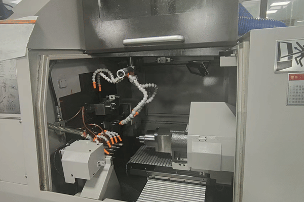
“We do not judge a part from G-code alone. The approved drawing, material, stock, fixture, tools, offsets and inspection criteria define whether the machining result is acceptable.”
Zhenling Engineering TeamDefinition-to-Machining Check Chain
- Lock the authorized definition: approved three-dimensional model, two-dimensional drawing and revision.
- Confirm the process plan: material, stock, datums, operation order and acceptance criteria.
- Match the machine context: postprocessor, control, machine type, axes and options; Confirm the postprocessor, control, machine type, axes and options for the intended machine.
- Review the program state: Units, plane, distance, feed, compensation, work offsets, and tool offsets.
- Run a virtual check using a toolpath, stock or machine simulation to represent the actual configuration.
- Complete controlled verification under the machine and factory procedure before release.
- Submit measured feedback on inspections and process observations to the job record.
Engineering Note
A 2024 peer-reviewed CNC methodology separates programming, simulation, postprocessing, controller-integrated virtual-machine verification and physical machining. MIT’s workflow likewise places stock and coordinate definition, process and tool selection, toolpath verification, postprocessing, transfer and machine setup in distinct stages.
Failure surface
Modern Machine Shop separates program failures into formatting, process and setup mistakes, and notes that a previously proven program can still fail after a setup error. Syntax acceptance is therefore one checkpoint, not a release decision.
PROCESS & CAPABILITIES
How We Work: From G-Code Literacy to a Made-to-Drawing Part
Program text is one component of a manufacturing definition. To decide what the supplier must supply, the material, stock, datums, critical dimensions, surface specifications, quantity, the method of inspection, and approved revision are all factors.
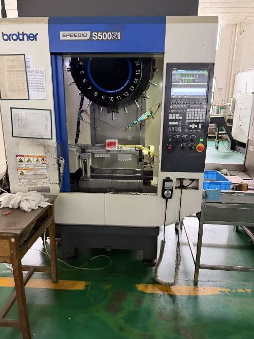
Zhenling manufacturing scope
Shanghai Zhenling Hardware Co., Ltd. was established in 2006 with manufacturing in Jiashan County, Zhejiang Province, China. We operate an 8,000 square metre site with a 6,000 square metre workshop.
Machining equipment
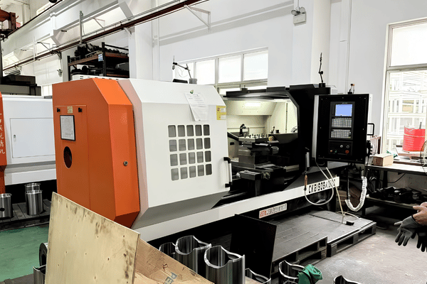
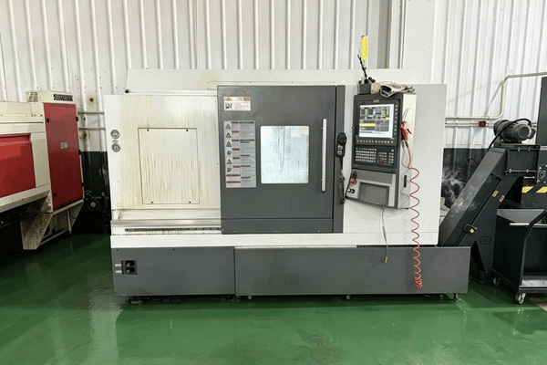
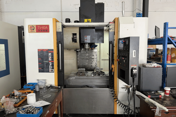
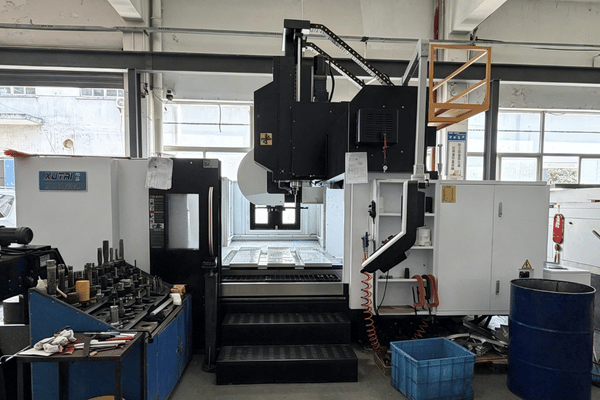
Our equipment includes CNC wire-cut EDM, lathes, milling machines, grinding machines, boring machines and radial drilling machines. We also operate 3-axis and 4-axis machining centres and imported 5-axis machining centres.
Material families
We process carbon and alloy steels, stainless steels, nickel-based alloys and aluminium alloys. Grade, condition, hardness and acceptance criteria are reviewed against the drawing.
Made-to-print components
We manufacture complete machine assemblies, flanges, rollers, bent pipes, valve bodies, plugs and custom-machined parts. That manufacturing scope does not imply ownership of a buyer’s controller setup or postprocessor.
RFQ Evidence Checklist
| Send | What it resolves |
|---|---|
| Approved revision | Which model and drawing govern the quotation |
| STEP and IGES models with 2D drawings | Geometry, dimensions, tolerances, notes and datum intent |
| Material and condition | Stock route, machining response and document requirements |
| Quantity and batch pattern | Setup share, fixture route and production planning |
| Critical features and acceptance method | Inspection scope and reporting plan |
| Existing program context, when relevant | Revision ownership and responsibility boundaries, not a promise of controller validation |
Where a G-Code Example Is the Wrong Evidence
A code sample can teach syntax and state, but it cannot prove that a real part, fixture, tool assembly or machine envelope is represented. Whenever a production decision is made, replace the example with the relevant engineering record.
Machine safety remains site-specific
OSHA’s general machine-guarding requirement addresses hazards created by moving machine parts, points of operation and flying material. A public reference page cannot replace the employer’s guarding, training, lockout and operating controls.
Situation
Why the example is insufficient
Use instead
Releasing a live setup
The snippet has no verified offsets, tools, stock, fixture or clearance state
Approved program package, setup sheet and shop release procedure
Moving between controls
Syntax, parameters, defaults and supported cycles can change
Exact controller manual and matched postprocessor
Changing a drawing revision
A proven program can represent superseded geometry or acceptance criteria
Revision-controlled model, drawing, program and inspection plan
Claiming a safe toolpath
A text review does not model the actual machine, stock, fixture or holder
Configuration-matched verification plus controlled machine procedure
Approving a supplier
Code literacy does not prove material, process or quality capacity
Capability evidence, drawing review and written quotation
INTERACTIVE RESOURCES
CNC G-Code Basics Interactive Tools
CNC Program Block Decoder
Translate complex G-code lines into clear, human-readable instructions. Validate syntax and parameter relationships instantly.
Modal Group Conflict Checker
Identify contradictory commands within the same block. Ensure safe modal state transitions before executing the toolpath.
G90/G91 Positioning Visualizer
Compare absolute and incremental endpoints dynamically. Prevent toolpath deviations caused by coordinate state errors.
PROCESS INITIATION
Send Your Drawing for a Machining Review
Attach the approved revision, material, quantity, critical features and inspection needs. One of Zhenling’s engineers will examine the manufacturing package for a made-to-drawing quotation. This page should not be used for controller validation or machine setup.
FAQ: CNC G-Code Basics
G-code is a family of preparatory commands and address words used by numerical controls to interpret motion, coordinates, modes, offsets and cycles. The exact language is bounded by the control, machine type, options and postprocessor.
G-codes usually establish geometric or preparatory states such as motion, plane and units. M-codes usually address machine functions or program flow, with meanings that depend closely on the builder and control.
Start with blocks, words, coordinates, modal groups, G00/G01 motion, G17/G18/G19 planes, G20/G21 units, G54 work coordinates and G90/G91 positioning. Keep the controller manual beside the program for cycles, compensation, macros and machine functions.
G54 selects stored work-offset data; it does not create the datum from the drawing by itself. The result depends on the offset table, machine coordinate, active tool compensation and whether the program is using G90 or G91.
Arc direction and centre data depend on the active plane, control format and whether the example uses radius or centre-offset words. Verify G17, G18 or G19 and the exact controller rules before reusing an arc block.
No single compact list establishes every mill and lathe behavior. A shared address-word foundation exists, but axis conventions, compensation, cycles, feed modes, parameters and options require machine-specific references.
No. It is intentionally incomplete and has no cutting-depth move, spindle command, tool call, coolant state, verified offsets, fixture, stock or controller validation.
Check the authorized drawing revision, material, stock, process plan, controller, postprocessor, tools, fixture, units, modal state, work and tool offsets, clearances, verification result and inspection plan. Qualified personnel then follow the machine and factory release procedure.
This page does not make that claim. Zhenling’s evidenced scope here is made-to-drawing metal component manufacturing and drawing-led quotation review.
Quotes are returned within 2-3 working days on business days, reviewed by an engineer, and prototype parts ship in 7-10 business days after drawing approval. Prototype orders start from 1 piece, and an NDA is available on request.
We work from STEP and IGES models with 2D drawings. Dimensional inspection reports and material certificates are available on request.
Orders use a 50% deposit with the balance before shipment. We ship EXW and FOB; the exact written scope is fixed in the quotation.



