

CNC planning tools and manufacturing review
Machining Calculators for CNC Planning
- Two task-focused tools
- Metric and inch workflows
- Drawing-led review
- Made-to-print quotation handoff
Use Zhenling machining calculators to provide a practical starting point, select the right reference, and bring the result to a made-to-print CNC machining enquiry. The hub separates quick calculations from the decisions about the machine, tool, material, tolerance, and inspection, which all still require engineering judgment.
When you submit your enquiry, indicate any confidentiality, file-control, or restricted distribution requirement.
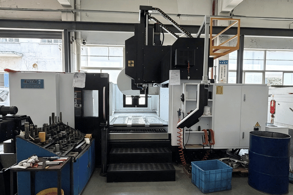
How We Work: Choose the Right Machining Calculator
The parent hub provides a selection of tasks from which the user can select the appropriate option. Each child page has its own calculation or reference data. Open the calculator tool that matches the task, and return to this hub for the calculation-to-drawing handoff.
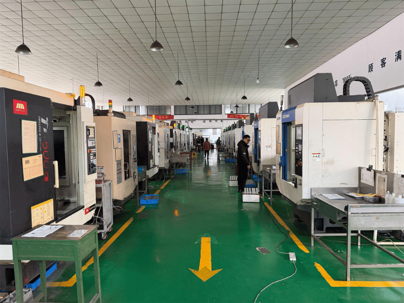
Selection shortcut
Open the child page that correlates to the task and confirm its scope prior to use. A cost estimate, tolerance release, or request for quote still requires a review of the drawing.
Speeds and Feeds Calculator
From this machining calculator hub, open the child page for the Speeds and Feeds Calculator.
- Page role: dedicated calculator route
- Hub relationship: linked child page under Machining Calculators
- Use boundary: Review the inputs, outputs, and instructions displayed on the page.
Tap Drill Chart
Open the child page for the Tap Drill Chart from this machining calculator hub.
- Page role: dedicated chart route
- Hub relationship: linked child page under Machining Calculators
- Use boundary: Review the references and instructions displayed on the page.
SPECIFICATIONS
Material Inputs for CNC Machining Calculations
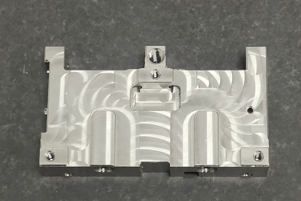
Material family and condition affect starting data, selection of cutting tools, chip formation, heat generation, and finish in milling, turning and drilling. Before a generic calculation result becomes a production instruction, a detailed review of the exact grade and condition is required.
01
Carbon and Structural Steels
- Grades in our material scope include 20#, 45#, Q235A, and Q345D.
- Confirm hardness, stock condition, and whether the operation is roughing or finishing.
- Use cutter-manufacturer data as the primary cutting-condition reference.
02
Alloy and Bearing Steels
- Our machining scope includes GCr15, 25CrMo, 42CrMo, and 12CrMoV.
- Heat treatment and hardness will determine the tool grade and allowable chip load.
- State the required condition on the drawing or enquiry.
03
Stainless Steels
- Our listed stainless steel grades include 303, 304, 304L, 316, 316L, and 321.
- More important than a generic material label are work hardening, heat control, and reliable chip evacuation.
- Separate free-machining grades from corrosion-led grade choices.
04
Nickel-Based and Corrosion-Resistant Alloys
- In our registered materials, we have C276, 904L, and nickel-based alloys for chemical service.
- Use application-specific tool data and conservative engagement assumptions.
- Confirm heat, corrosion, and pressure exposure before material release.
05
Aluminum Alloys
- Our range of aluminum alloys is drawing-led.
- The starting value is dependent upon chip evacuation, temper, cutter geometry, and flute spacing.
- Long-reach tools and thin walls require an additional stability check.
06
Another Grade or Condition
Send the material designation along with the condition, drawing revision and supporting documentation with your calculator output. The drawing review is used to determine whether the material and process for the component are suitable before the production quotation is issued.
SYSTEM PARAMETERS
Inputs That Change the Calculation
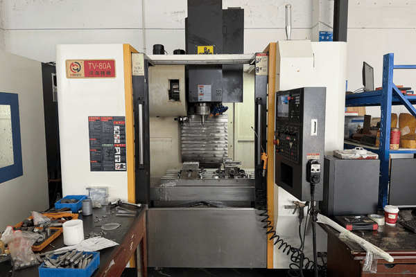
A correct formula can yield the wrong shop-floor starting value when an input hides a setup constraint, even if the calculator returns a precise number. Use the matrix to determine which value should enter the calculator and which condition is for the engineering review.
Engineering judgment
When a calculator result appears aggressive, confirm the assumptions rather than automatically reducing every value by an arbitrary percentage. The limiting factor may be radial engagement, spindle torque, or workholding rather than the arithmetic.
| Input or condition | Why it matters | What to verify |
|---|---|---|
| Tool diameter | It directly changes the spindle-speed relationship. | Use the effective cutting diameter at the point of contact. |
| Cutting speed | It links the material and tool pair to RPM. | Start with the cutter manufacturer’s data for the actual grade and coating. |
| Feed per tooth | It connects chip formation to feed rate. | Match cutter geometry, flute count, engagement, and material. |
| Radial and axial engagement | Chip thinning and tool load change with engagement. | State width of cut, depth of cut, and toolpath strategy. |
| Machine limits | The spindle or feed system may not reach the calculated ideal value. | Check maximum and minimum RPM, feed range, power, and torque. |
| Rigidity and workholding | Deflection and chatter can set a lower practical limit. | Review stick-out, fixture support, part wall thickness, and clamping. |
| Coolant and chip evacuation | Heat and recutting alter tool life and surface finish. | Confirm coolant route, air blast, and chip-clearance path. |
| Finish and tolerance | A roughing value is not automatically a finishing value. | Separate stock removal from the final feature and inspection requirement. |
Engineering Specifications
Calculation Method and Unit Reference
The series of equations below explain how the calculator works and show the units throughout the explanation. These are planning equations rather than released production instructions.
Calculation boundary: Zhenling Metal engineers check the unit chain because a mixed metric and inch input creates release risk. NS TOOL’s metric spindle-speed relationship uses the factor 1000, so the units must remain explicit from input through result.
Quantity
Reference relationship or rule
Review note
Metric cutting speed
Vc = π × D × n ÷ 1000
Vc in m/min, D in mm, n in min−1.
Metric spindle speed
n = Vc × 1000 ÷ (π × D)
Check the calculated value against the machine’s available RPM.
Milling feed rate
Vf = n × fz × Z
Vf in mm/min; fz is feed per tooth; Z is the number of cutting edges.
Tool diameter input
D > 0 mm
Use the effective diameter when geometry changes the contact point.
Cutting speed input
Vc > 0 m/min
Source the starting value from the cutter and material pairing.
Active edge count
Z is an integer ≥ 1
Count active cutting edges for the operation being calculated.
Length conversion
1 in = 25.4 mm
Do not mix inch diameter with metric cutting speed in one equation.
Surface-speed conversion
1 SFM = 0.3048 m/min
Convert once, then keep one unit system through the calculation.
PROCESS REFERENCE
From a Calculator Result to a CNC Machining Quote
Price follows material, geometry, tolerance, quantity, inspection, finishing, and schedule more than a fixed calculator price. Your result can support the discussion, but the drawing and acceptance criteria control the quotation.
What Moves the Price
| Driver | Cost mechanism | Useful buyer action |
|---|---|---|
| Material and stock form | Availability, stock allowance, heat treatment, and yield affect the route. | State grade, condition, certificate need, and approved alternatives. |
| Geometry and access | Deep pockets, thin walls, long reach, and multiple setups add machining and control time. | Supply the 3D model plus a controlled 2D drawing. |
| Tolerance and inspection | Tight or datum-dependent features require stable setups and more measurement. | Identify critical-to-function features instead of applying one tight tolerance everywhere. |
| Quantity and schedule | Setup share, fixture strategy, tool consumption, and capacity allocation change with volume and date. | Provide prototype, batch, and annual quantity bands with the required delivery date. |
Quote and Prototype Planning
Engineer-reviewed quotation
The quotation is based on an engineering review of the drawing, material, quantity, inspection, finishing, and required date. Any missing input that affects process or price must be resolved in the written offer.
Prototype machining
The prototype is dependent on drawing approval, material, process, inspection, finishing, and shipping. The written quotation states the manufacturing and shipping schedule.
Commercial handoff
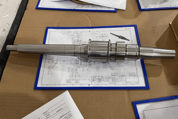
Submit a usable 3D model with a controlled two-dimensional drawing, and state the required delivery location and trade term. Identify your requested trade term location and delivery term. The quote captures the file basis, the scope, schedule, and the commercial terms for the specified part.
PROCESS CONTROL
Calculation Review and Quality Assurance Handoff
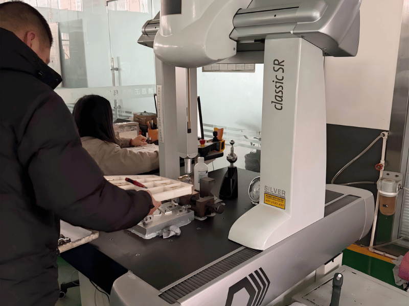
A machining calculator and a drawing provide controls, respectively, on the arithmetic and the satisfaction of the finished component. The two are linked by a short review process that defines the value as the process starting point.
Release Checks
- Verify units and variables. Verify diameter, surface speed, chip load, active edges, and output units for discrepancies.
- Check tool-material pairing. Verify the given data along with the recommendations by the tool supplier and the specified material condition.
- Set machine and setup limits. Review the available spindle, feed, power, rigidity, workholding, reach, and chip removal.
- For turning and other operations, return to the drawing. Align the operation with tolerance, datum, finish, thread, inspection, and documentation requirements.
01
Information to keep with the result
- Calculator name and unit system
- Every input value and its source
- Tool designation and effective diameter
- Machine, workholding, and coolant constraints
- Drawing revision and affected feature
02
Documents to define for the order
State the dimensional report, material record, and any necessary quality documents prior to quoting. Acceptance is upon the controlled drawing and the document scope confirmed in the written order.
Workflow Protocol
How We Work: Calculation-to-Drawing Handoff Map
The handoff map stops planning numbers from becoming unofficial assumptions on the shop floor. Each step adds details needed to be responsible for the next call.
01
Select the task.
Use the speed-and-feed chart for cutting motion or the tap drill chart for the preparation of a threaded hole.
02
Record inputs.
Keep the unit system, material, tool data, diameter, and the thread callout together along with the result of your calculations.
03
Add the machine context.
State the machine, spindle range, workholding, reach, coolant, and engagement limits.
04
Attach the controlled design.
Send an available 3D CAD model with the two-dimensional PDF drawing, revision, quantity, and inspection needs.
05
Check manufacturability.
During the engineering review, the process route, critical features, material state, and measurement method are examined before quotation.
06
Release in writing.
The quote includes the accepted scope, schedule, documents, trade term, and the next manufacturing step.
Drawing Details That Prevent Rework
Feature
What to specify
Why it matters
Critical diameters
Nominal size, tolerance, datum, and measurement condition
Prevents a general tolerance from controlling a functional fit by accident.
Threads
Applicable ISO or other governing standard, size, pitch or TPI, class, depth, and inspection method
Separates a drill-size lookup from the complete threaded-feature requirement.
Surface finish
Target area, roughness callout, and post-process condition
Distinguishes roughing parameters from the final pass and inspection state.
Material
Grade, condition, substitution rule, and certificate requirement
Connects the calculation to the actual stock and cutting-data source.
COMPANY OVERVIEW
Industries We Support and Zhenling CNC Machining Context
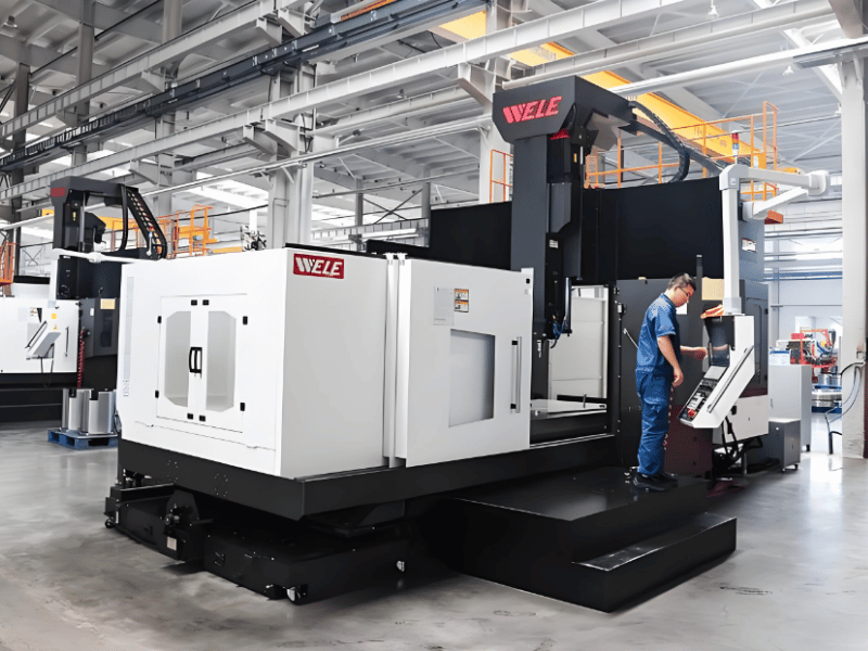
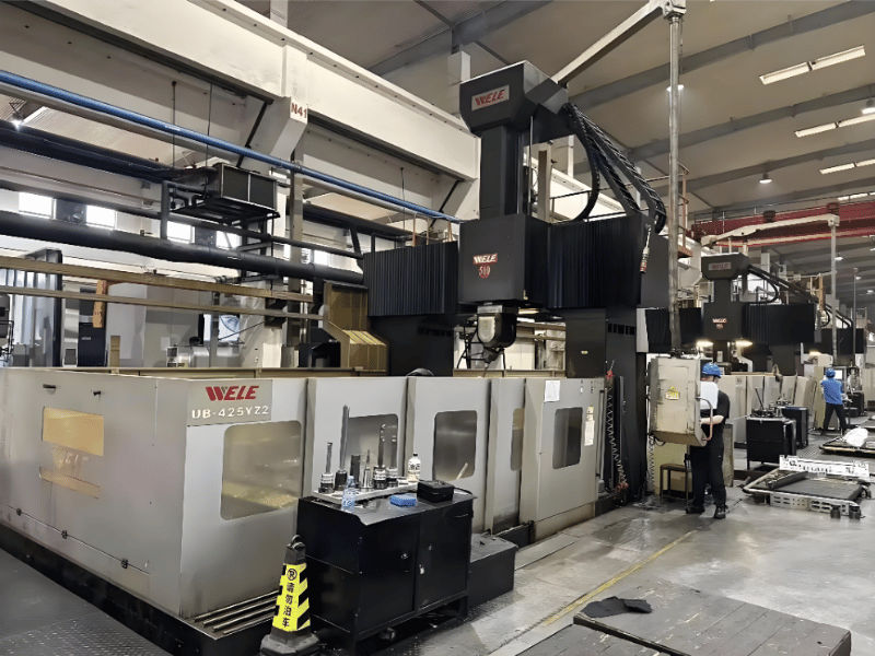
Established in 2006, Shanghai Zhenling Hardware Co., Ltd. operates an 8,000 m² factory site with 6,000 m² of workshop space in Jiashan, Zhejiang. The company manufactures made-to-print non-standard components, complete machine assemblies, flanges, rollers, bent pipes, valve bodies, plugs, and other custom-machined parts.
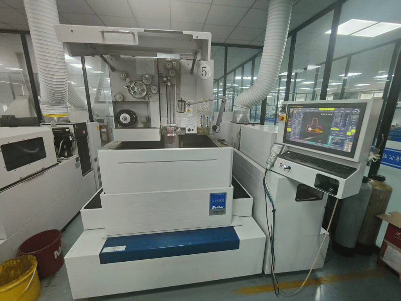
Manufacturing Equipment and Processes
- We machine non-standard components from controlled drawings and physical samples.
- Our component range includes complete machine assemblies, flanges, rollers, bent pipes, valve bodies, plugs, and custom-machined parts.
- We operate CNC lathes, milling machines, grinding machines, boring machines, and radial drilling machines.
- We run three-axis, four-axis, and imported five-axis machining centers.
- We use wire-cut EDM equipment for profiles and narrow features.
- Broader fabrication uses CNC shearing, plate rolling, presses, submerged-arc welding, and gas-shielded welding.
- We process carbon steel, alloy steel, bearing steel, stainless steel, nickel-based alloys, and aluminum alloys.
- We review material selection for high-temperature, corrosive, and high-pressure service conditions.
Industrial Application Context
Pressure Equipment
Made-to-print components for pressure-vessel and related equipment applications.
Oil-Gas Separation
Custom metal parts and assemblies for separation equipment and supporting systems.
Fluid Control
Components that require material and drawing number control, such as valve bodies, plugs, and flanges.
PROCESS LIMITATIONS
Where Simple Machining Calculators Stop
A calculator is rarely the final word when making a decision on stability, toolpath, process capability, or controlled acceptance. It can help you set a starting range, but define each limitation with an assigned owner.
| Situation | Why the calculator is incomplete | Better next step |
|---|---|---|
| Thin walls, long reach, or flexible workholding | Deflection and chatter are setup-dependent and are not solved by the basic formula. | Review support, stick-out, engagement, and toolpath before release. |
| Hard, heat-treated, or difficult alloy | A broad material category does not define tool grade, edge preparation, or usable cutting data. | Start with tool-maker data for the exact condition and confirm a controlled trial. |
| Critical threaded feature | A tap-drill value does not define thread class, depth, engagement, or inspection. | Put the complete thread callout and acceptance method on the drawing. |
| Cost, lead time, or production release | The arithmetic omits stock route, setup count, inspection, finishing, quantity, and schedule. | Send the result with the drawing for a written process and quotation review. |
Practical boundary
The maximum calculated material-removal rate is not always the lowest-cost operating condition; the trade-off includes machine stability, tool life, surface finish, and parts per tool. A calculated maximum is not a substitute for tool-maker data and setup validation, and the required compromise depends on the job. The wrong answer is to apply one safety factor across every machine.
Engineering Tools
Machining Calculators Hub
Select the appropriate engineering tool below to establish stable baseline parameters, verify drawing inputs, and build a controlled calculation handoff for your CNC machining RFQ.
Calculator Selection Check
Determine the most appropriate machining calculator based on your specific material, feature requirements, and setup constraints.
CNC RFQ Input Checklist
Review critical drawing tolerances, inspection requirements, and commercial inputs before submitting a request for quotation.
Calculation Handoff Builder
Compile your machining calculations, tool data, and drawing specifications into a structured, engineer-ready handoff document.
ENGINEERING REVIEW
Request a Drawing and Calculator Review
Please send the result, controlled drawing, material, quantity, tolerance, required date, and inspection details. The review will connect the math behind the process and support the engineer-reviewed quotation.
Attach
- Available 3D CAD model
- Two-dimensional PDF drawing
- Calculator inputs and output
- Material and quantity
State
- Critical tolerances and threads
- Surface and inspection requirements
- Target delivery date
- Required material documentation
Use machining calculators for planning. Make the production decision through a controlled drawing and review.
Request a Drawing Review →
KNOWLEDGE BASE
FAQ: Machining Calculators
This is a purpose-built calculator for spindle speed, feed rate, chip load, etc. Though one can use the results from this calculator for planning, this calculator cannot factor in all of the constraints of the machine, setup, tool, or drawing. Because of this, it cannot be considered a fully functioning machining planning tool.
Use the Speeds and Feeds Calculator when the cutting task title matches, then verify whether its displayed scope covers RPM or feed rate. Use the Tap Drill Chart when the task title matches, then verify whether its displayed scope covers the thread callout or drill size.
Some calculator providers use their own libraries for cutting data, tool assumptions, engagement models, safety factors, machine limits and so forth. Start by checking the inputs and then check the result against the cutter manufacturer’s starting data and the actual setup.
No. NS TOOL relationships concern themselves with calculation, while spindle range, feed range, torque, rigidity, workholding, coolant, tool reach, and material conditions determine the usefulness of the result.
Before you solve, you must convert the calculations to a single unit system. Use 1 inch = 25.4 mm and 1 SFM = 0.3048 m/min for conversion. Be sure to label each input and output you saved.
No. The drawing should also include the thread standard, the nominal size, pitch or TPI, class, depth, amount of required engagement, and the required inspection method.
A simple machining calculator can’t price the whole job. It takes a review of the drawing to understand the material, geometry, setup, tolerance, inspection, finishing, quantity, and schedule. Then an engineer quotes a price.
Send a usable 3D model with a controlled two-dimensional drawing, including the revision, material, quantity, delivery date, and inspection requirements. Also, include the name of the calculator, the unit system, the inputs, and the results.
The drawing, availability of the materials, process route, inspection, finishing, quantity, and delivery location all play a role in determining timing. Use the written quotation as the controlling schedule.
State the required confidentiality, file-control, and restricted-distribution terms with your enquiry. These specific terms and conditions must be agreed to in writing for reliance to be permitted.
The Zhenling site contains a calculator and chart that can help you in the planning stage. The calculator and chart outputs remain subject to tool, machine, material, setup, drawing, and inspection review before production release.



