CNC Tooling Guides for Milling and Workholding Decisions

CNC tooling guides are designed for machining with the workpiece, cutter, tool holder, and workholding solution integrated as one machining system. The guides help you find the right solution. Bring unresolved machining issues about access, fixtures and inspection to Zhenling for answers in a drawing review.

01
Cutter choice
02
Workholding strategy
03
Drawing inputs
04
Machining review
CNC Tooling Guides for Milling and Workholding Decisions
NOTICE

This is a resource for manufacturing decisions, not a cutting-tool store. Zhenling reviews made-to-print metal parts; your selected tool brand, holder interface and machine limits remain part of the project input.

Choose Your Tooling Guide

Start with what is blocking your choice for the machining plan. The two guides are designed to be separate, so cutter taxonomy would not cover issues of datum, clamp and fixtures.

Types of Milling Cutters

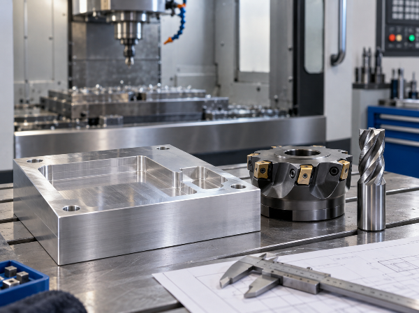
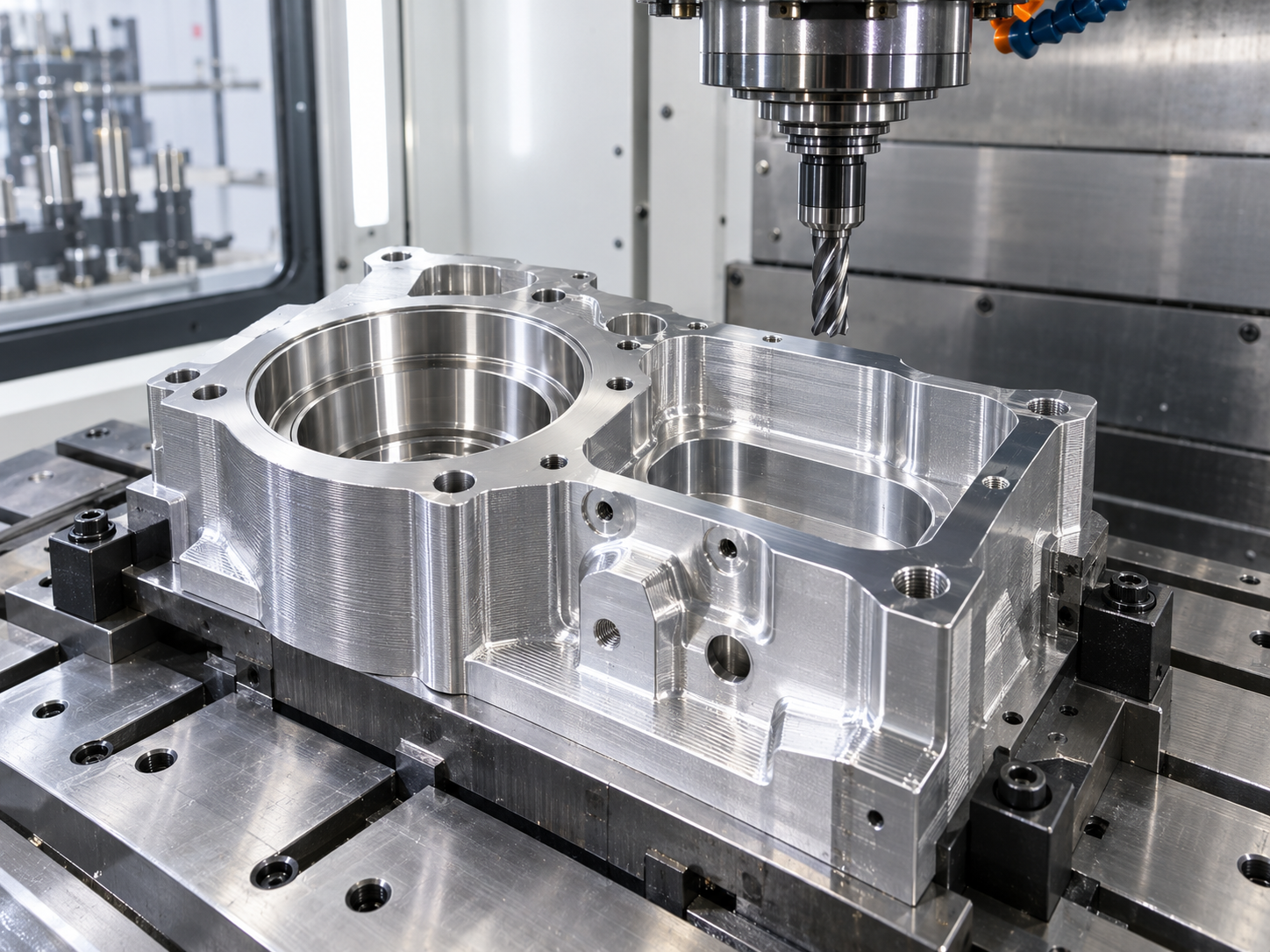
Compare CNC milling tools by the feature they create and the limits they introduce. This route covers end mill, face mill, ball end mill, bull-nose end mill, roughing end mill, shell mill, fly cutter, thread mill, chamfer mill, countersink and drill-bit relationships.

  • Associate a milling cutter family with a face, pocket, slot, contour, chamfer, hole, or internal thread.
  • Analyze cutting edges, flute space, corner radius, insert construction and tool material.
  • Identify where reach, chip evacuation, cutting forces and surface finish require more project data.
Open the Milling Cutter Guide

CNC Workholding

Compare how a vise, chuck, collet, fixture plate, jig, pallet, soft jaws, toe clamps, modular fixtures and vacuum workholding position and secure a part. This route separates locating, support and holding force instead of treating every problem as a tighter clamp.

  • Vacuum fixtures can improve support on thin plates, but lateral restraint still has to resist shifting.
  • Use a stable datum and repeatable part positioning to control degrees of freedom.
  • Allow the cutting tool to access the top and the required sides of the workpiece.
  • Review clamping force, thin-wall distortion, jaw contact, fixture rigidity and inspection access.
Open the CNC Workholding Guide
Choose Your Tooling Guide

Tooling Decisions Work as a System

A CNC machine does not experience the tool in isolation. A holder or spindle nose can become the limiting envelope in a deep or awkward cavity, even when the cutting edge itself fits.

“Milling vibration can arise due to limitations in the cutting tool, the holding tool, the machine, the workpiece or the fixture.”

Sandvik Coromant, How to Reduce Vibration in Milling

Original engineering framework

The following seven items can act as a release checklist. Leaving a row blank is not a reason to guess; get a closing answer before the CNC program and setup are frozen.

Safety compatibility is a release condition

Workholding and tool access must remain compatible with the machine’s required guards and operating procedure. OSHA 1910.212 addresses point-of-operation, rotating-part and flying-chip hazards; use the machine manufacturer’s instructions and your site safety process for the final setup.

Cutter, Holder, Workholding Fit Map

Input What it changes Evidence to bring Release check
Part feature Points toward face milling, profile milling, slotting, drilling, threading, chamfering or contour work. Marked feature, entry direction, depth and adjacent geometry. The selected milling tool can enter, cut and leave without collision.
Workpiece material Changes tool material, edge geometry, coating, cutting forces, heat, wear and chip behavior. Material family, grade, hardness or condition. The tool supplier’s data covers the stated material and operation.
Production quantity Moves the balance among general-purpose workholding, custom fixturing, modular systems, automation and setup efficiency. Prototype quantity, batch size and expected recurrence. Fixture preparation and verification effort fit the production volume.
Machine interface Defines spindle, tool-holder, table, travel, power, torque and controller constraints. CNC mill or machining-center model, taper/interface and available travel. The planned assembly fits the machine tool and its instructions.
Tool reach Changes rigidity, runout sensitivity, holder clearance, feed-rate limits and chatter risk. Feature depth, neck clearance and shortest usable assembly. Reach is no longer than the geometry requires.
Workholding access Sets datum stability, supported faces, jaw or clamp clearance and sides of the part available in one setup. Raw stock, finished model, clamp zones and fixture envelope. The tool, holder and spindle housing clear the fixture through the toolpath.
Inspection requirement Influences datum transfer, setup count, probing access and the order of machining operations. Critical dimensions, engineering tolerance, surface callouts and report need. Features can be measured against the intended datum without an uncontrolled reorientation.

Workpiece Material Changes the Tooling Question

Material names narrow a tooling search, but the grade and condition control the final answer. Zhenling processes carbon and alloy steels, stainless steels, nickel-based alloys and aluminum alloys for custom-machined parts.

Grades Scope

Grades in the supplied manufacturing scope: 20#, 45#, Q235A, Q345D, 12CrMoV, GCr15, 25CrMo and 42CrMo.

Tooling Question

confirm hardness, stock condition, heat-treatment sequence and whether interrupted cutting is present.

Drawing Input

+Drawing input: identify critical faces, holes, threads, datum features and any post-machining heat treatment.

Grades Scope

Grades in the supplied scope: 303, 304, 304L, 316, 316L, and 321.

Tooling Question

evaluate work hardening, heat generation, edge condition, chip control and the need for a rigid setup.

Drawing Input

Drawing input: state the exact grade, surface requirement and any passivation or corrosion-related acceptance note.

Grades Scope

Grades named in the supplied scope: C276 and 904L, plus nickel-based alloys for chemical applications.

Tooling Question

Verify tool material, carbide insert grade, coating, engagement and tool-life monitoring with the selected supplier.

Drawing Input

Drawing input: Provide material certification, hardness, heat condition and surfaces that define acceptance.

Grades Scope

Scope: Various aluminum alloys used for made-to-print non-standard components.

Tooling Question

review sharp cutting edges, flute capacity, chip evacuation, workholding contact and thin-wall movement.

Drawing Input

Drawing input: identify alloy and temper, cosmetic faces, flatness-critical areas and parts that need distributed support.

Workpiece Material Changes the Tooling Question

Tool material and coating are conditional choices

High-speed steel, cemented carbide, solid carbide tools, carbide inserts and coated tools address different constraints. Titanium nitride and titanium aluminium nitride are coating terms, not automatic recommendations. The selected cutting material, heat path, speeds and feeds, and tool-holder stability still have to match the job.

Submit Specifications

Surface Requirements Connect Geometry, Setup and Inspection

Surface quality is the result of the entire machining operation process and not just one cutter. Zhenling Metal reviews edge condition, feed rate, tool path, runout, rigidity, workpiece support, corner radius and the nature of the material against the drawing.

Surface Requirements Connect Geometry
Specify

Mark the functional surface

Identify sealing faces, bearing seats, sliding surfaces, cosmetic zones and interfaces. Place the engineering tolerance and finish callout on the 2D drawing instead of automatically treating every face the same way.

Mark the functional surface
Verify

Trace the force path

Look at where the vise, jaw, chuck, collet or fixture supports the stock and where the cutting forces enter. Even with the nominal cutter choice appearing reasonable, thin walls may chatter or relax after unclamping.

Trace the force path
Approve

Connect machining to measurement

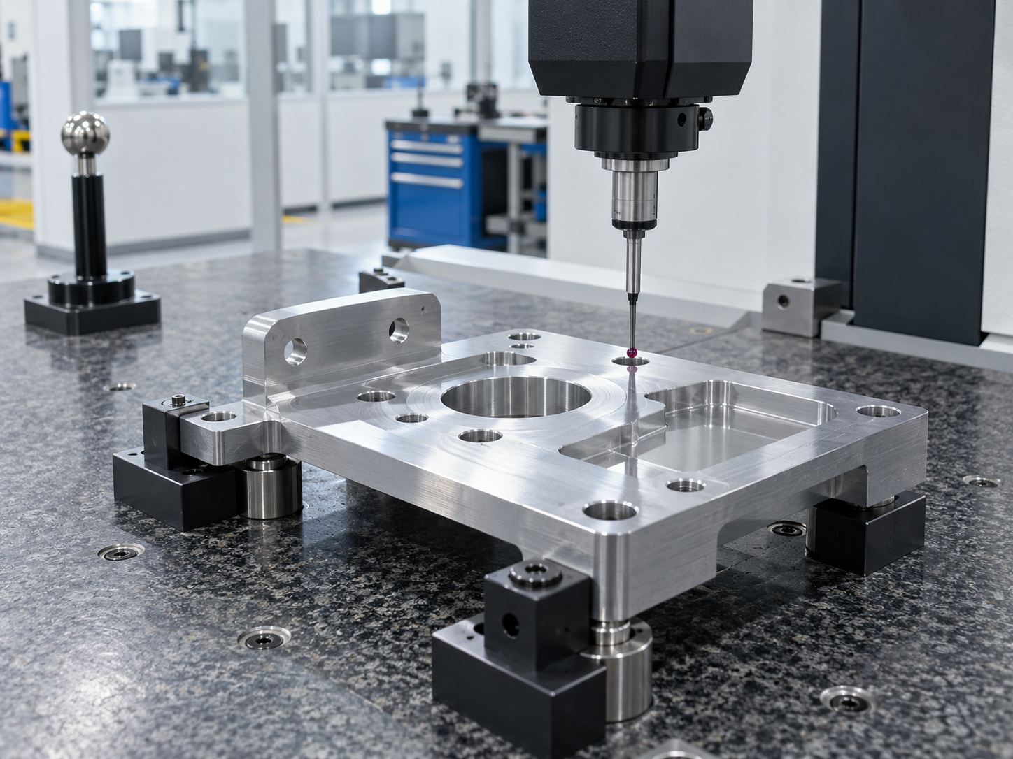
Define the datum, measurement method and inspection access before production. This keeps machining accuracy and the inspection result tied to the same part positioning logic.

Connect machining to measurement

Why a new cutter may not remove chatter

A fresh end mill cannot correct a flexible workpiece, excessive overhang, poor holder condition or an unstable fixture. Identify the problem before replacing only the cutting tool.

Machining Context Behind the Guides

These specifications describe the manufacturing platform used for Zhenling drawing reviews; they do not represent a cutting-tool inventory or indicate that one machine, tool or fixture will cover every part.

Explore Context
Machining Context Behind the Guides
Manufacturing fact Zhenling context Why it matters to tooling review
01Operating history Established in 2006 with manufacturing in Jiashan County, Zhejiang Province, China. Reviews are grounded in made-to-print production work rather than a retail tooling catalogue.
02Factory site 8,000 m² (86,111 ft²). Supports a mixed manufacturing environment for non-standard components and assemblies.
03Workshop 6,000 m² (64,583 ft²). Provides the shop-floor context behind process, access and equipment questions.
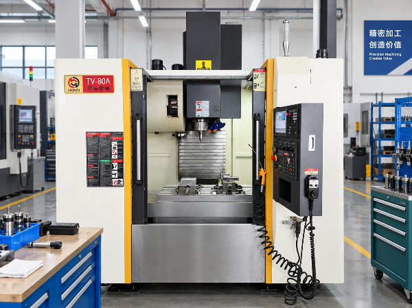
043-axis machining Multiple 3-axis machining centers. Orientation count and fixture access remain central process-planning variables.
054-axis machining Multiple 4-axis machining centers. Rotary access can reduce repositioning, subject to part and fixture clearance.
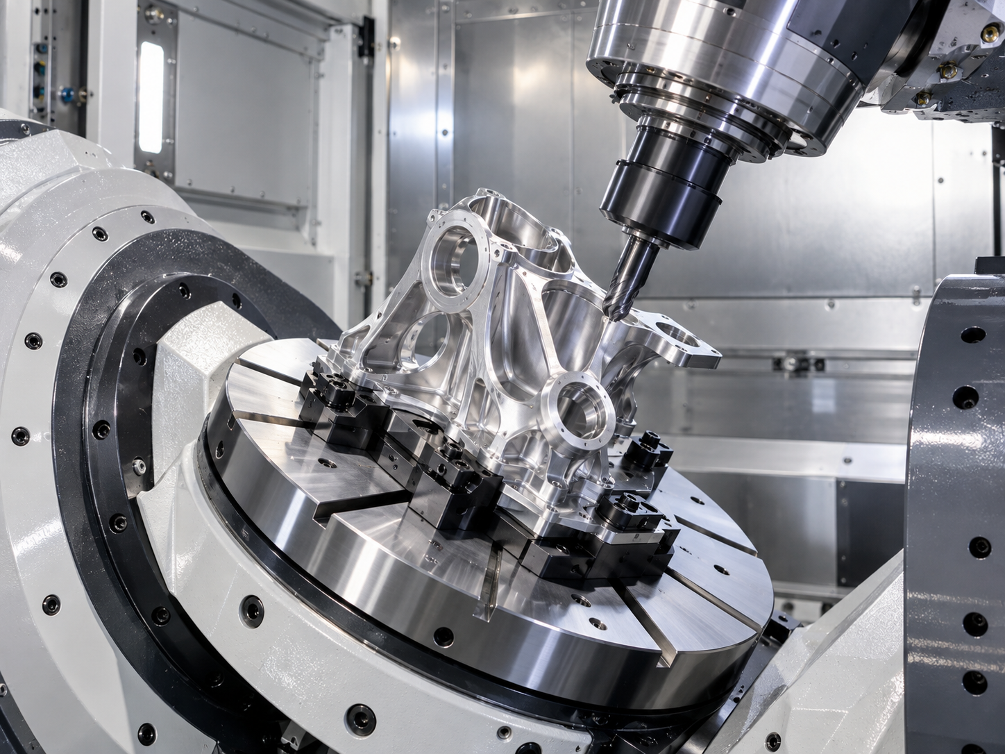
065-axis machining Imported 5-axis machining centers. Multi-axis motion still requires a workholding envelope that clears the spindle and tool.
07Steel examples 20#, 45#, Q235A, Q345D, 12CrMoV, GCr15, 25CrMo and 42CrMo. Grade and condition must reach the cutter, tool-holder and machining plan.
08Stainless examples 303, 304, 304L, 316, 316L and 321. Work hardening, heat and chip behavior change the tool-selection conversation.

Access and Setup in the Cost Model

Zhenling Metal prices custom machining from the drawing, material, quantity, process route and inspection requirement. The same visible geometry can produce a different quotation because access, workholding preparation, tool changes and verification work change the manufacturing route.

Access and Setup
24 hours

We return engineer-reviewed quotations within 24 hours on business days after the required drawing inputs are available.

5–7 business days

Prototype parts ship in 5–7 business days after drawing approval. The written quotation fixes the production schedule for your part.

From 1 piece

Prototype orders start from 1 piece, allowing the first setup and inspection approach to be reviewed before a production run.

Cost driver Mechanism Useful buyer input
Setup orientations Each reorientation adds handling, datum transfer and verification work, while a feature relationship that crosses two setups can also require an intermediate reference or an inspection step before the next clamping operation begins, particularly when a bore, sealing face and bolt pattern share a positional requirement that cannot be recovered from an unverified secondary datum. Mark features that must remain related to one datum structure.
Tool reach Long assemblies can reduce rigidity and change the safe machining envelope, and the holder or spindle housing may become the collision limit before the cutting edge reaches the deepest programmed surface. Provide pocket depth, opening size and adjacent obstruction geometry.
Fixture preparation Soft jaws, custom fixturing, a fixture plate or modular workholding may add preparation, yet that preparation can support repeat production when the same datum, clamp sequence and verification method are reused across batches. State prototype quantity, production volume and likely repeat orders.
Material response Hardness, wear, heat and chip behavior affect machining time and tool-life planning, while the supplied condition can change whether roughing, stress relief, heat treatment and finishing belong in one route or several controlled stages. Give the exact material grade and condition.
Surface and tolerance Critical callouts can add finishing passes, stable support and inspection steps, especially when a functional face must remain related to a bore, thread or sealing feature after the workpiece is released from its fixture. Control only the surfaces and dimensions that carry functional risk.
Inspection access A feature that is difficult to reach during machining may also be difficult to measure from the intended datum, so the process plan needs enough physical space for the selected gauge, probe or inspection fixture. Name the report, datum and acceptance method needed for release.

Risk Checks Before a Tooling Decision

Here are the checks to perform prior to treating a cutter family or workholding method as released. Each item has clear follow-on actions to provide evidence related to manufacturing instead of a vague ‘high quality’ statement.

Check Item Issue Description Required Action
Datum instability
Locators or clamping points allow the workpiece to shift between operations. Define the primary, secondary and tertiary locating surfaces and verify them on raw stock.
Excess clamping force
Thin walls, soft material or stressed stock deform under the holding force. Distribute support, control jaw contact and inspect after release when relaxation is plausible.
Insufficient restraint
Cutting forces overcome friction or support and the part moves. Review force direction, stop locations, clamp geometry and holding force.
Cutter clearance
The cutting edge reaches the feature but the tool shank, holder or spindle housing does not. Check the whole assembly through the programmed toolpath.
Chip evacuation
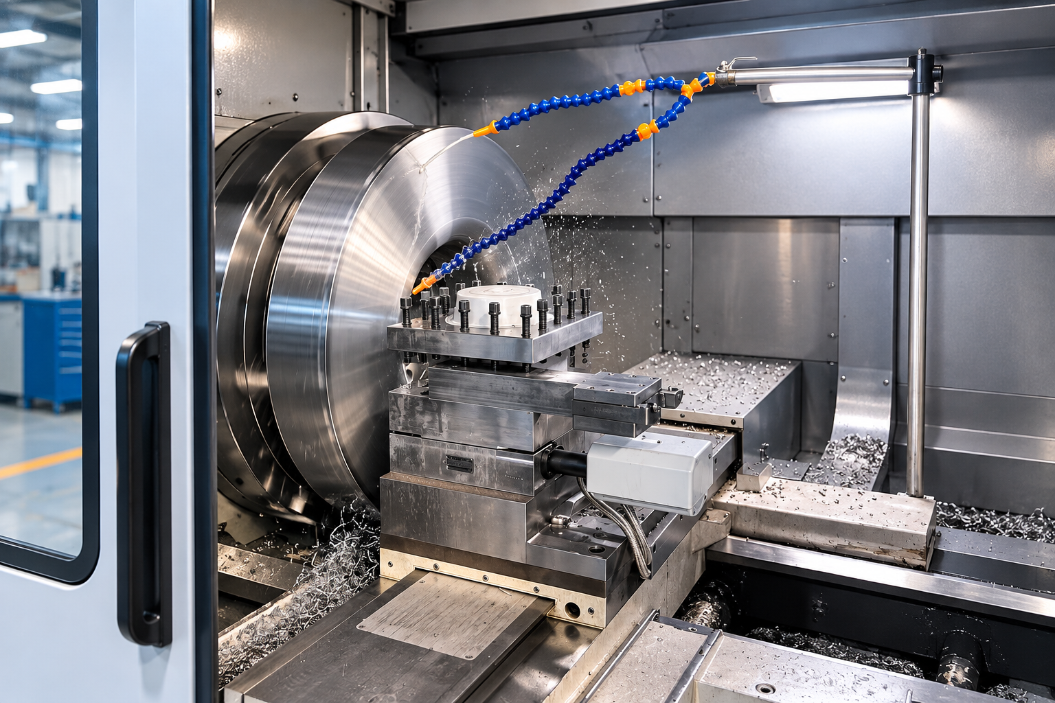
Flute space, pocket depth or coolant access allows recutting and heat buildup. Match flute count, engagement and evacuation strategy to the material and cavity.
Inspection access
The released fixture hides the surface or datum needed for measurement. Plan measurement access with the same model used for machining access.
Guard compatibility
A fixture or loading method obstructs required protection or creates a new exposure. Keep guards functional and validate the setup under the machine and site safety procedure.

From Drawing to Machining Review

  • Send the available files. We work from STEP, IGES and X_T models. Use the 2D drawing for tolerances, threads, surface notes and datum intent.
  • Confirm material and quantity. State the grade, condition, prototype quantity, batch size, and expected recurrence of production.
  • Mark the critical features. Identify the surfaces, holes, pockets, threads, fits and edges that control function.
  • Review cutter access. We identify entry direction, reach, holder clearance, corner geometry, cutting-tool family and chip-removal queries.
  • Review workholding and inspection. We examine locating, support, clamping, reorientation, toolpaths and measurement access against the drawing.
  • Close questions and quote. We return the manufacturing questions that must be resolved before production and issue the written quotation against the agreed scope.
From Drawing to Machining Review Stage

Send these seven inputs

Ensure all criteria are prepared for a comprehensive engineering assessment.

  • 3D model and 2D drawing
  • Material grade and condition
  • Quantity and repeat forecast
  • Critical dimensions and datums
  • Surface and edge requirements
  • Inspection or document needs
  • Delivery destination

Build an RFQ-ready checklist

The Drawing Input Builder turns available project facts into a structured review summary. It does not upload a file or send an enquiry. Use the page contact button when you are ready to start the review.

Review & Analysis

We review the submitted drawing and identify the manufacturing questions that must be resolved before production.

Drawings are handled as confidential, and an NDA is available on request before file review.

Zhenling’s Custom Machining Context

Shanghai Zhenling Hardware Co., Ltd. has manufactured non-standard metal components since 2006 from its Jiashan County facility. Our support covers review of drawings and samples throughout the process to finished parts and assemblies.

Made-to-print component scope

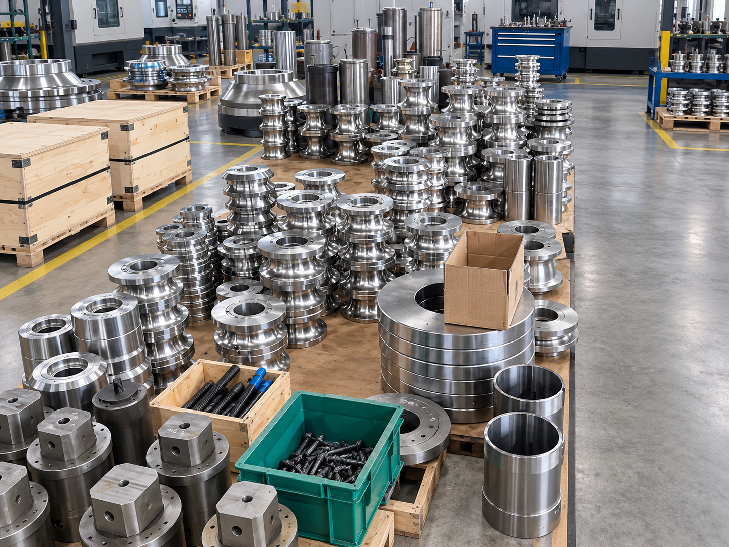
We manufacture complete machine assemblies, flanges, rollers, bent pipes, valve bodies, plugs and custom-machined parts. These components serve pressure-vessel, oil-and-gas separation, fluid-control and other industrial equipment applications.

Machining equipment categories

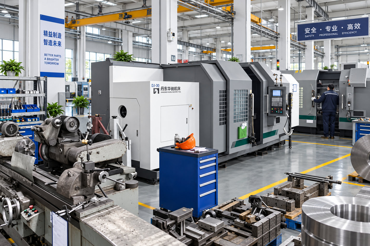
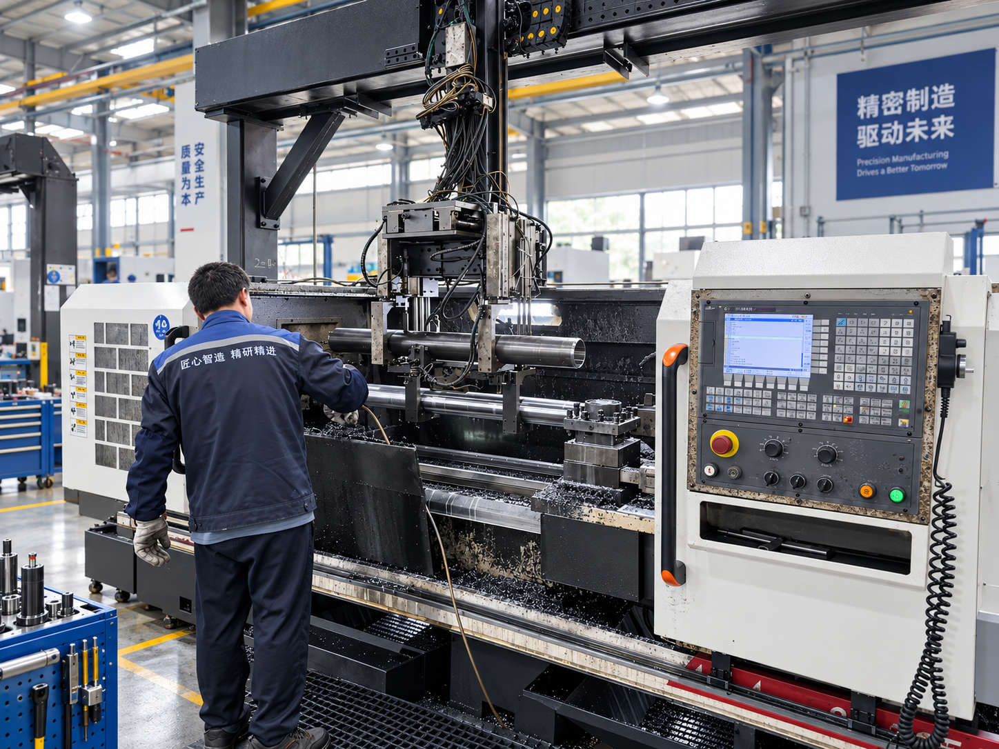
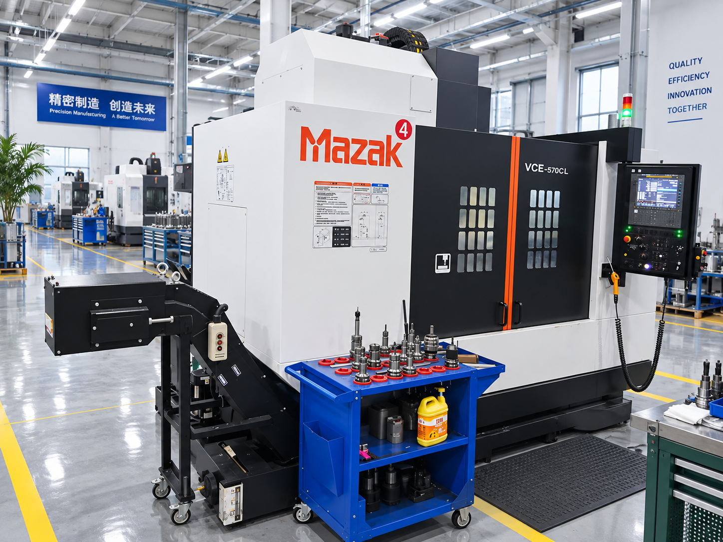
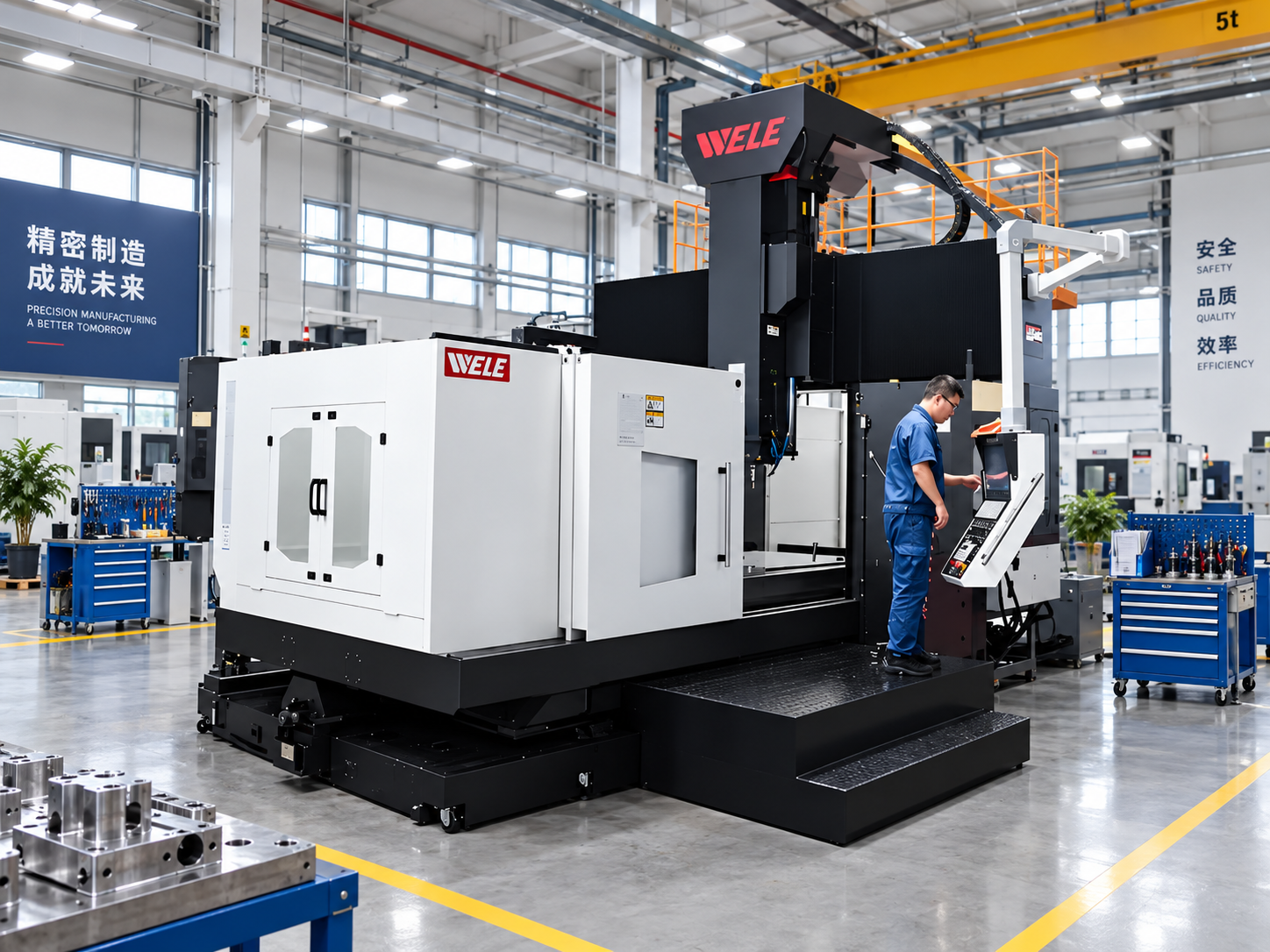
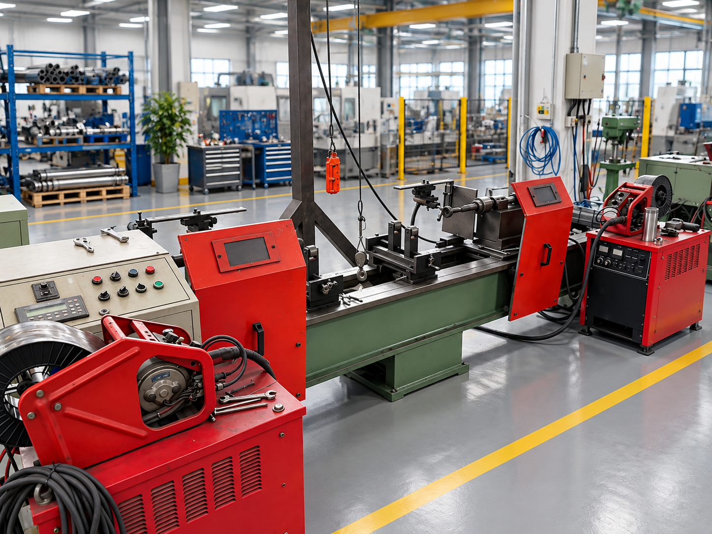
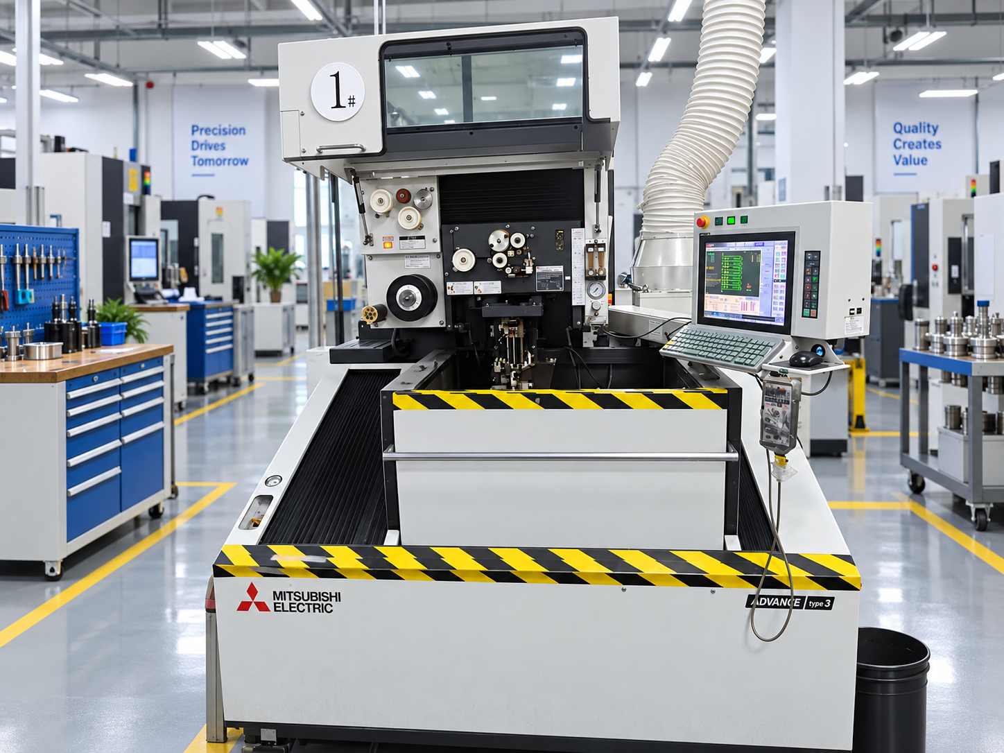
We use CNC wire-cut EDM, lathes, milling machines, grinding machines, boring machines and radial drilling machines. Our manufacturing base also includes 3-axis, 4-axis and imported 5-axis machining centers.

Zhenling custom machining components overview

Material-selection context

We evaluate specialty steels, stainless steels, nickel-based alloys, and aluminum alloys based on temperature, corrosion, and pressure resistance and hardness. The exact grade of each part needs to be confirmed based on its operating environment.

Order documentation and shipping

Dimensional inspection reports and material certificates are available on request and scoped in the quotation. We ship DDP, with other Incoterms available on request.

Where a General Tooling Guide Stops

A detailed guide can help organize a decision, but it cannot replace limitations of a machine, supplier cutting data, fixture validation, or a controlled proving cut. Whenever the required input is missing, use the exit route in the third column.

Stop condition Why the guide is insufficient Next action
Material grade or hardness is unknown “Steel,” “aluminum” or “plastic” is too broad for a final edge, coating, speed, feed or tool-life decision. Confirm the material specification and condition before selecting the right tool.
Feature entry is not defined A nominal cutter can fit the feature diameter while the shank, holder or machine cannot reach it. Mark entry direction, depth, adjacent walls and collision envelope on the model.
Critical surface requirements are missing The machining plan cannot balance roughing, finishing, tool change and inspection without acceptance criteria. Add tolerance, datum and surface-finish callouts to the drawing.
Machine or holder interface is unknown The spindle, holder, collet, chuck and available length set physical limits. Confirm the CNC machine and tool-holder interface, then use the tool supplier’s data.
Workholding has not been proven A vise or modular fixture may provide access but still allow movement, jaw lift or part distortion. Validate part positioning, support, clamp sequence and post-release dimensions.
Safety method conflicts with access Convenient loading or fixture placement does not override required guarding and operating controls. Revise the setup under the machine manual and site safety procedure.
  • The types of CNC equipment used in CNC machining do not, by themselves, select a cutter or fixture.
  • A tight tolerance needs a datum and inspection method before anyone can call one route the right CNC setup.
  • A machinist must clamp the workpiece securely to work on a part, but too much clamping force can deform a thin or stressed part.
  • A coating may extend tool life only when the substrate, edge, engagement, heat path and supplier data fit the operation.
  • Aerospace requirements are not assumed for this manufacturing scope; state any market-specific standard or acceptance rule in the request.

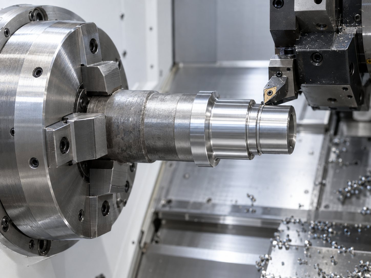
Reamers, taps, dies, turning tools, abrasive wheels, engraving tools and specialty tools may follow or replace a milling operation. A CNC lathe, CNC grinding machine, CNC router or horizontal milling center also changes the appropriate workholding and tool path.

Where a General Tooling Guide Stops

CNC Tooling Questions from Engineers and Buyers

It includes the cutting tool, tool holder, workholding device, setup hardware, measurement references and the data needed to run the machining operation. On a modern CNC milling machine, the spindle interface, cutter assembly, fixture system, workpiece and program all affect the result.

The cutter needs a clear path to the feature, while the workholding system must locate and secure the part against cutting forces. A clamp or jaw that blocks the path can force a longer tool, another orientation or a different milling operation.

The cutting tool has the cutting edge that removes material; examples include an end mill, face mill, drill, reamer and thread mill. The tool holder connects that tool to the spindle and contributes interface accuracy, reach, runout and rigidity.

Compare them when a planar surface can be reached in more than one way. Coverage, machine power, holder clearance, workpiece support, required edges and the remaining features can reverse an initial preference.

Greater reach raises deflection and vibration sensitivity and may reduce usable cutting data. Review the shortest assembly that clears the pocket, then check the holder, neck, flute and chip-evacuation envelope.

Jaws, clamps, fixture bodies and the machine table occupy the same physical envelope used by the tool and spindle housing. Five-axis CNC movement improves approach options only when the fixture leaves the required clearance.

Send the 3D model, 2D drawing, material, quantity, critical dimensions, surface and inspection notes, and delivery destination. Add the CNC machine and holder interface when the review is for an existing production setup.

This page does not feature cutting tools, tool holders, vises or fixture systems for sale. Zhenling uses tooling and workholding knowledge to review the manufacturability of made-to-print metal components.

Yes; we review feature access, material, production volume, machining centers, tool reach, fixture access and inspection requirements, then return the manufacturing questions that must be closed before production.

Our supplied manufacturing scope covers carbon and alloy steels, stainless steels, nickel-based alloys, special alloys and aluminum alloys. Please provide the exact grade and condition so that the machining and tool selection review can be specific.