Manufacturing knowledge guide
CNC programming is not just the act of writing G-code. For engineering or purchasing, it means carrying part intent through design data, manufacturing choices, machine context, and a controller-readable output. This guide explains that information chain before machining begins. The guide is not a controller-code lesson, a software ranking, a program-release procedure, or a substitute for machine-safety verification.
Search results often lump together many different intents under the same heading. Beginners may want to learn CNC programming, study the basics of CNC, take online courses, or build the programming skills of a CNC programmer. Another reader may be comparing types of CNC programming such as manual programming, conversational programming, or CAM programming. Those are valid learning questions, but this article is for the engineering conversation that happens before someone programs CNC machines for a particular part. The article does not explain g-code programming line by line or judge what makes a good CNC programmer.
Computer numerical control is the full term behind CNC, but an understanding of CNC starts with recognizing that programming involves more than an instruction format. In the manufacturing industry, a CNC process connects a part definition to a finished product through people, machines, and controlled information. This framework is very helpful in modern manufacturing where the work is distributed over design, process planning, machine operation and document control.
CNC programming PDF, CNC programming examples, CNC programming code, CNC programming online, and CNC programming jobs are separate queries outside this guide’s pre-machining information-handoff focus.
The practical question
Before asking whether a CNC program can be created, ask whether the team has described the part, the process intent, the setup assumptions, the available machine context, and the current revision clearly enough for any program to represent the intended manufacturing situation. For a structured scope check before code, use Zhenling’s CNC Programming Scope Selector.
CNC Programming Connects Context, Not Just Code
What is CNC programming?
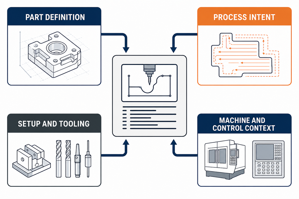
At a broad level, CNC programming connects manufacturing information to machine-readable instructions for a particular operation. The result may be a CNC program containing G-code and M-code, but that output sits late in the chain. Several earlier decisions determine the part, the features that matter, how it can be held and reached, and the machine and controller environment that will interpret the outcome.
NIST’s discussion of STEP-NC is useful here because it frames the boundary as an information problem: feature-based CAM information can be translated toward CNC part-program information, while conventional paths may reduce richer process knowledge into motion-oriented output. That does not make one architecture universal, but it does show why “the code” is an incomplete description of the work. See the NIST STEPNC++ publication for the context of feature-based CAM/CNC.
Engineering takeaway: A CNC program is an output of a controlled information chain; machine context, process decisions, and revision control still need to accompany it.
| Information layer | Question it answers | What can go wrong if it is missing |
|---|---|---|
| Part definition | What geometry and requirements are intended? | Even a correct-looking path may represent the wrong requirement. |
| Process intent | What sequence and feature logic are needed? | The operation order is assumed rather than clarified. |
| Setup and tooling | How can the part be referenced, held, and accessed? | Tool access or datum assumptions remain hidden. |
| Machine and control context | Which resource will interpret the output? | Transferability is assumed without checking the relevant conditions. |
This reference guide keeps to the context of conventional pre-machining information interfaces. There are different boundaries of information and responsibility for runtime monitoring, adaptive control, release authorization, and safety verification.
Which Inputs Actually Shape a Machine-Ready Program?
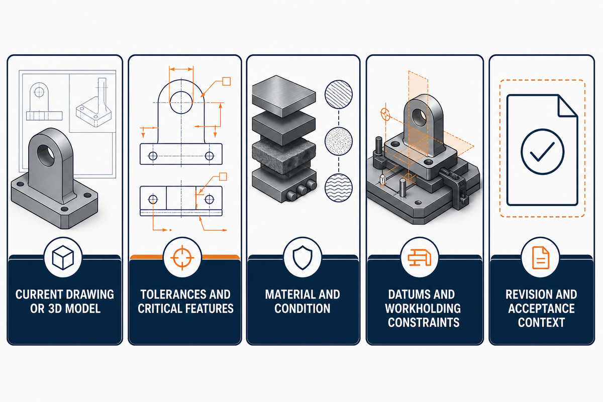
An open machining dataset described in a 2025 research paper separates product-geometry data, NC-code data, and high-frequency machine data; the distinction is a helpful reminder that different information serves different purposes. The paper’s data description identifies toolpaths, feed rate, and cutting speed in its NC files rather than treating geometry alone as the complete record.
For a custom part, the starting point isn’t a universal checklist. It’s a focused discussion around what the supplied fields will affect. The table below is an editorial aid rather than a factory standard.
| Input | What it communicates | Why the programming conversation may change |
|---|---|---|
| Current drawing or 3D model | Feature geometry and overall form | It establishes what must be represented, not every manufacturing decision. |
| Tolerances and critical features | Which relationships need particular attention | They influence how features are interpreted and sequenced. |
| Material and condition | The stock or finished-material requirement | It changes the context for cutting decisions without prescribing one set of values. |
| Datums and workholding constraints | How the part should be related to a physical setup | They affect accessible faces, orientation, and coordinate assumptions. |
| Revision and acceptance context | Which definition is current and how requirements are interpreted | A program should not silently bridge an unresolved drawing change. |
Where CAD Ends and CAM Begins in a Conventional Workflow
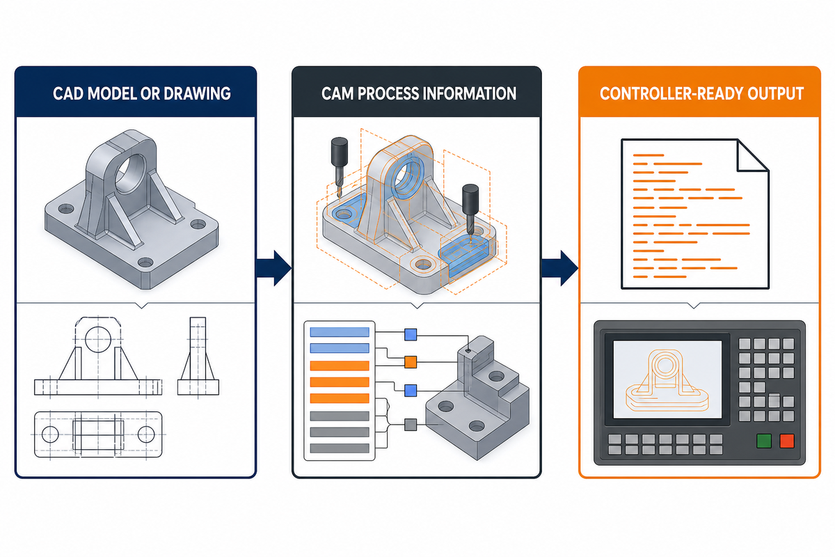
CAD and CAM are often discussed together because they connect, not because they perform the same role. CAD represents the part definition. CAM is commonly where manufacturing decisions are organized into toolpath and process information. A controller-oriented output may then be produced through a post-processing path.
Can CAD files directly generate CNC codes?
Some architectures can preserve more process information across that boundary; others use different direct or conversational approaches. The point is if a CAD file is used as an input, then it does not necessarily mean that a solution has been provided for every tool, setup, machine, or revision. The NIST STEPNC++ publication describes a feature-based CAM-to-CNC path in which STEP-NC preserves process information that conventional post-processing reduces to motion primitives.
| Representation | Primary role in this guide | Not claimed to decide automatically |
|---|---|---|
| CAD model or drawing | Communicate geometry and requirements | The full manufacturing route |
| CAM process information | Organize features, toolpaths, and machining intent | Missing definition or setup assumptions |
| Controller-ready output | Express instructions for a particular environment | Program approval, safe operation, or inspection acceptance |
This is why a guide about CNC programming can be helpful without recommending CAD/CAM software. Software selection is a separate decision; the continuity of information is the issue here.
For the same reason, this article does not compare CNC programming software, CAM software, simulation software, software tools, or a named package such as Fusion. A specific programming method is outside this guide’s scope. Whether a team uses machine programming at a control, conversational programming, or a CAM-led route, the missing-definition problem remains upstream of the software choice.
Process Planning Turns Features Into Cutting Decisions
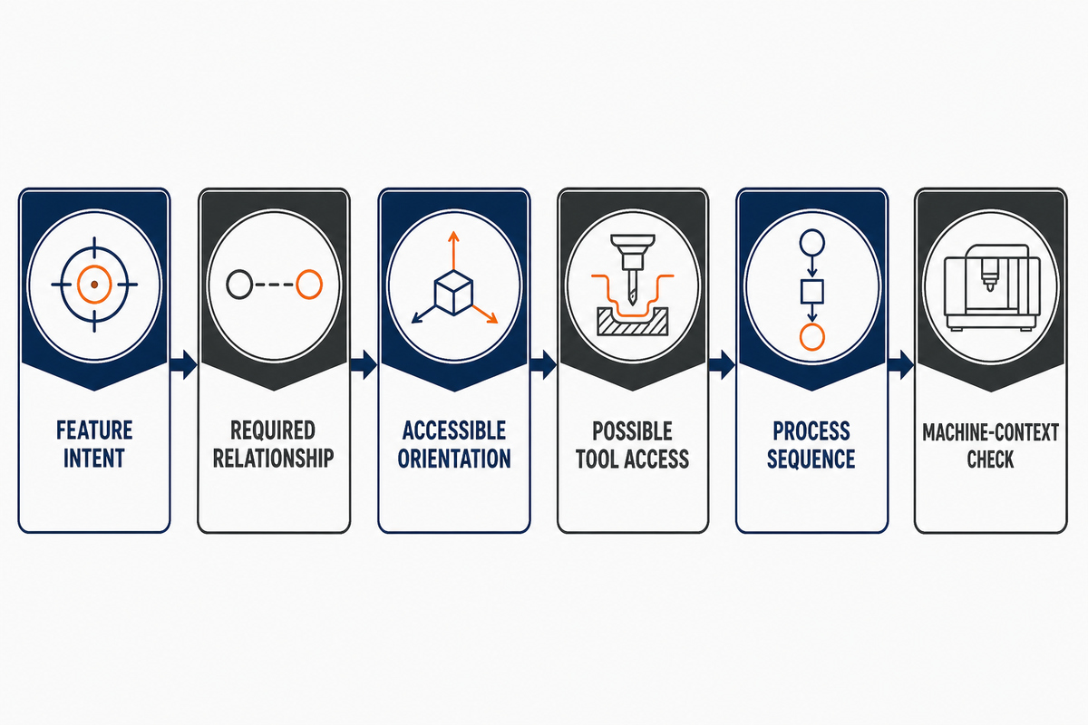
Part features do not arrive at a CNC machine as an already ordered process. A pocket, a bore, a sealing face, or a contoured surface can elicit questions about access, reference, tool selection, intermediate state, and relationship to the previous process. These are planning questions, not a code recipe. A CNC curriculum outline identifies process planning, technical documentation, setup, inspection, and quality control as separate manufacturing competencies.
A useful way to review the handoff is to follow one feature through a neutral chain: feature intent → required relationship → accessible orientation → possible tool access → process sequence → machine-context check. Each arrow is a place where an unspoken assumption can change the resulting CNC program.
Think about the vocabulary without turning this into a recipe. A mill, lathe, drill, CNC milling center, CNC turning resource, or CNC router may bring different machine types and access conditions to a machining process. The relevant tool path, cutting tool, tool movement, tool change, feed rate, and spindle speed are part of a programming process, but they are not interchangeable facts to copy from one machine operation to another. A machinist, CNC programmer, or machine operator still needs the part and process context before specific programming is meaningful.
Boundary note
This chain helps a buyer or engineer ask clearer questions. It does not suggest feeds, spindle speed, a tooling package, a setup sequence, or a release choice for any particular machine.
When Machine Context Changes the Same Part’s Program
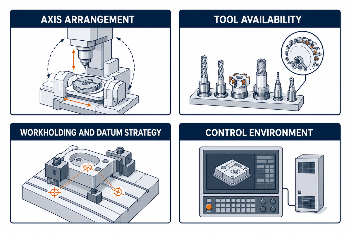
Machine context is not an incidental detail added at the end. The feature-to-process chain is where machine-context questions become explicit. For a controller-and-setup comparison, see Zhenling’s Machine–Post Compatibility Checker. ISO/TS 14649-201 describes machine-tool description data as process data for manufacturing. Part programming, process planning, simulation, and machine-tool evaluation are examples of its applications. See the ISO record for ISO/TS 14649-201 for that stated scope.
ISO 6983-1 frames interchangeability as a conditional goal for machines of the same classification by stated criteria, rather than a blanket guarantee or blanket impossibility. Rather, the question is which machine, process, function, size, and accuracy conditions are comparable.
| Context variable | Question to clarify | Why it belongs in the conversation |
|---|---|---|
| Axis arrangement | Which orientations and motions are relevant? | This affects how a feature may be approached. |
| Tool availability | Which cutting tools and tool changes are assumed? | Tool access is part of the process context. |
| Workholding and datum strategy | How is the part located and retained? | The datum strategy changes accessible surfaces and coordinate logic. |
| Control environment | What output conventions are relevant? | It is part of the translation boundary, not an afterthought. |
What a Post Processor Does, and Does Not Do
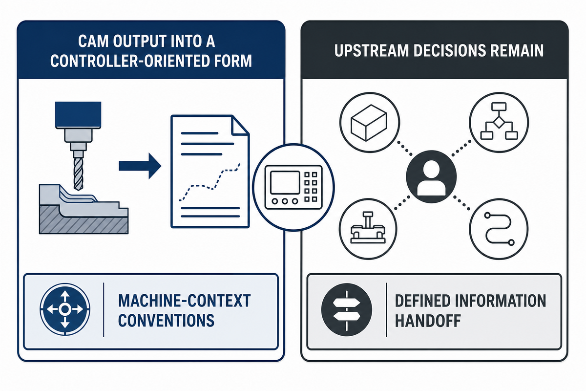
By convention, a post processor usually lies between CAM-related information and the expected output in a given controller context. That controller context is examined in the preceding machine-context check and should be checked with the machine context. It is important, but cannot act as a universal fix for decisions that were never made upstream.
| A post processor can help translate | A post processor does not decide for the team |
|---|---|
| CAM output into a controller-oriented form | Which drawing revision is authoritative |
| Machine-context conventions represented in the workflow | Whether a feature is accessible under the proposed workholding |
| A defined information handoff | Missing material, tolerance, datum, or process assumptions |
As a counterexample to any absolute statement that post processing should always be a discrete step, NIST’s STEP-NC shows a ”feature based path” intended to retain higher process knowledge. Treat post processing as a usual translation boundary, not an absolute law of every CNC architecture. The NIST STEPNC++ publication describes the feature-based CAM-to-CNC path used for this comparison.
Why G-Code Is an Output Layer, Not the Whole Definition
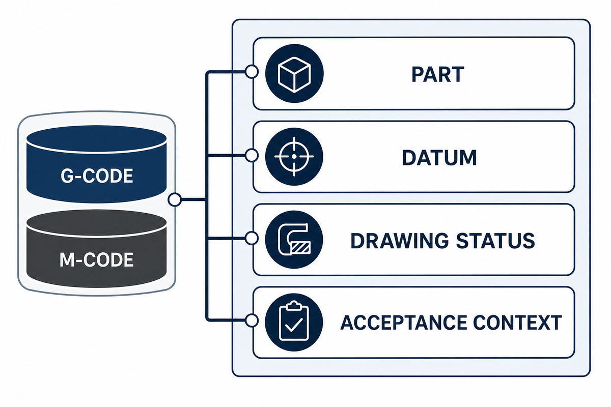
While g-code and m-code are programming-related terms, a code list does not carry the rationale that made an operation significant. As the NIST STEPNC++ publication explains, conventional post-processing can reduce CAM process information to motion primitives, so a code list does not preserve the full CAM context.
It does not indicate the reason for selecting the datum, the reason the feature is accessible through a tool, the status of the drawing, or the acceptance context.
That distinction also keeps this article in the right lane. Readers who need the basics of CNC programming, steps to learn CNC programming, or a path to become a CNC machine programmer need a different resource and a machine-specific process. Here, controlling CNC machines goes beyond providing a code list; different machine programming approaches are available to CNC operators and programmers. This article aims to assist teams identify the information that should exist prior to considering code as the final answer.
In other words, machine code is an output language, not a complete manufacturing definition. Programming CNC machines in industrial CNC or modern CNC settings still depends on the part and machine context described above.
Reading Dimensional Intent Before It Becomes Program Context
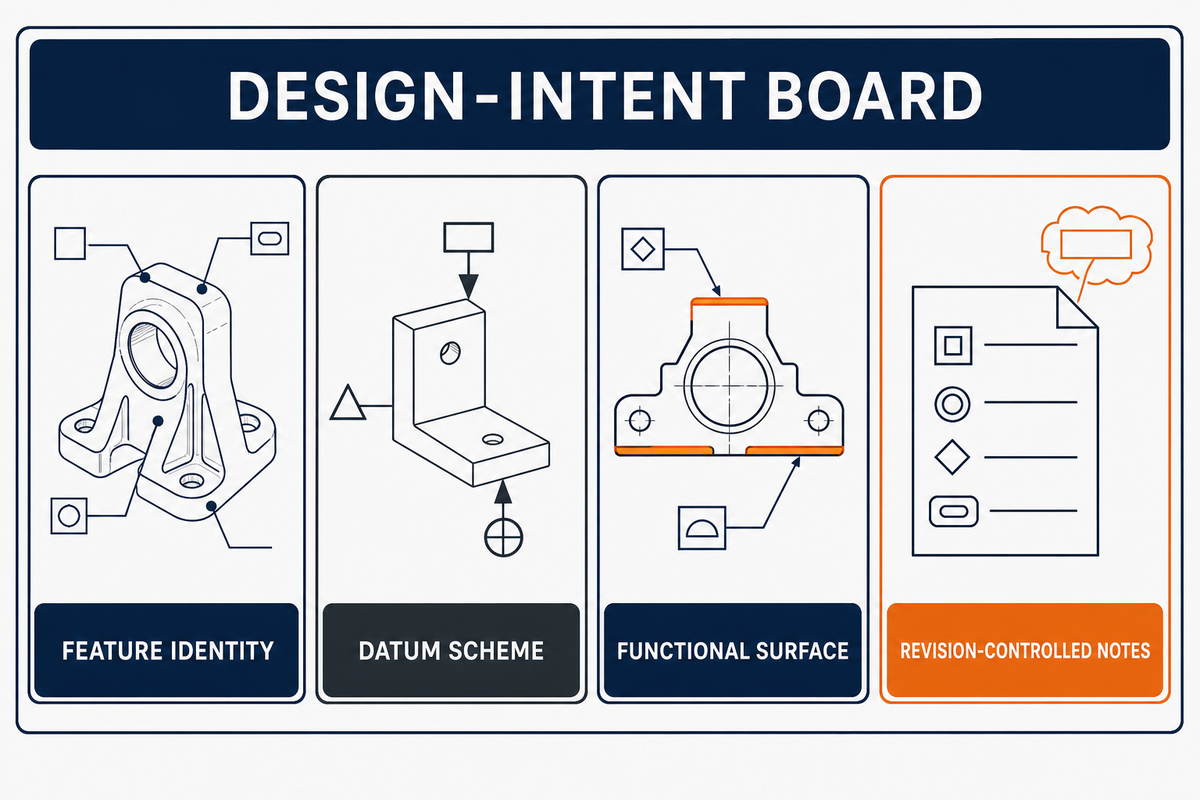
Dimensions and tolerances are not machine settings. They are examples of the design intent that a programming dialogue has to retain and make explicit. The values below are deliberately hypothetical notation examples, not recommended machining parameters, inspection instructions, quotations, or claims about a particular machine’s capability. Their purpose is to show why a model alone can leave important context implicit. The open machining-data study separates product geometry data and NC code data.
| Illustrative design notation | Context that still needs to be understood |
|---|---|
| 25 mm bore through a 12 mm wall | Feature identity, accessible direction, and the datum used to locate it. |
| 40 mm outside diameter with ±0.05 mm tolerance | Which condition is critical and how that requirement relates to the design definition. |
| 0.10 mm position relative to named datums | Datum scheme and the feature relationship that must remain visible upstream. |
| Ra 1.6 µm surface callout on a 60 mm face | Which surface is functional and whether the requirement applies to the full face or a bounded area. |
| M12 thread with 1.5 mm pitch and 18 mm depth | Thread specification, depth reference, entry condition, and revision-controlled notes. |
| 0.5 mm maximum edge break beside a 6 mm slot | Which edges are included, and whether the note has exceptions near functional features. |
| 3 mm stock allowance outside a 75 mm finished profile | The distinction between starting condition and finished geometry, rather than an assumed operation sequence. |
| 2 mm relief next to a 10 mm shoulder | Feature purpose, tool access, and the geometry that must be protected during later decisions. |
| 4 mm chamfer beside a 30 mm flange on a 100 mm body | The bounded edges and functional interfaces that the shorthand note is intended to cover. |
| 8 mm counterbore around a 14 mm clearance hole | Feature hierarchy and the relationship between the counterbore, hole, and documented datum scheme. |
A good programming brief should cite the current source of truth for the requirements and identify important functional relationships. It does not turn a short list of dimensions into an automatic machining plan. The selection of material, workholding, tool strategy, machine tool control, revision control and verification are separate decisions outside the scope of this brief.
The 6-Layer Machine-Ready Context Map
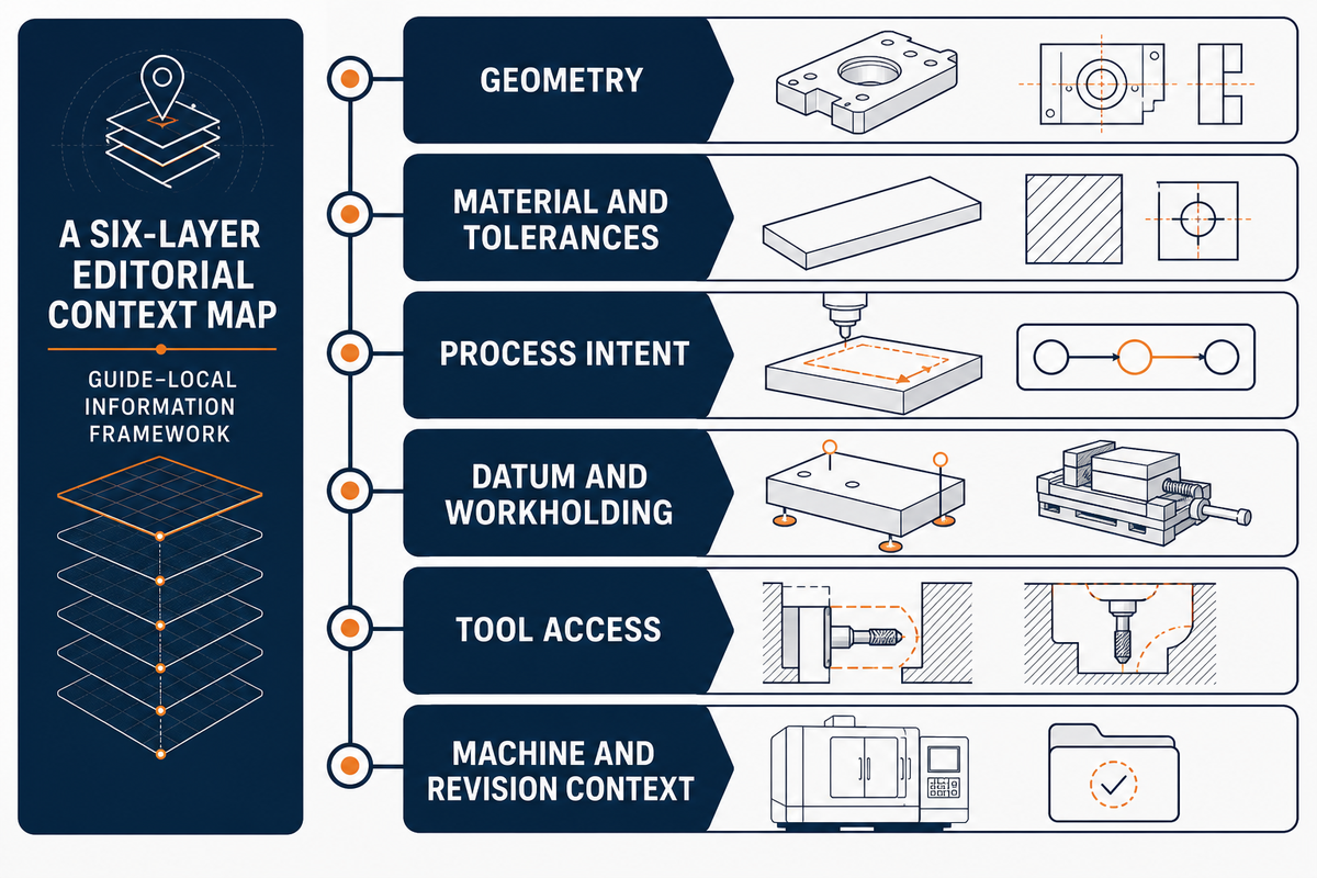
The 6-Layer Machine-Ready Context Map is this article’s editorial framework. ISO/TS 14649-201 lists CNC part programming, process planning, simulation, and machine-tool evaluation among its applications. It is neither an ISO standard, a factory procedure, nor a performance model. Its purpose is simple: when a programming discussion stalls, identify which layer contains the unanswered question instead of treating every gap as a coding issue.
| Question type | Ask this before treating it as a code issue | Context layer |
|---|---|---|
| Geometry type | Which feature and relationship must the definition preserve? | Geometry |
| Material type | Which material condition is actually specified? | Material and tolerances |
| Tolerance type | Which relationship is critical to the part intent? | Material and tolerances |
| Sequence type | What depends on an earlier operation? | Process intent |
| Datum type | What reference relationship is intended? | Datum and workholding |
| Workholding type | What must remain accessible after locating the part? | Datum and workholding |
| Tool-access type | Which approach or clearance is assumed? | Tool access |
| Machine type | Which machine and control conditions are comparable? | Machine context |
| Revision type | Which drawing or model revision is current? | Machine and revision context |
| Layer | Clarify this | Typical owner to involve |
|---|---|---|
| 1. Geometry | The current shape, features, and dimensional intent | Design engineering |
| 2. Material and tolerances | Material condition and critical relationships | Design and quality stakeholders |
| 3. Process intent | Feature priorities and operation dependencies | Manufacturing engineering |
| 4. Datum and workholding | Reference logic, locating, and access constraints | Setup and process stakeholders |
| 5. Tool access | Reach, clearance, and feature approach constraints | Process planning |
| 6. Machine and revision context | Machine classification, control context, and current document status | Programming, manufacturing, and document control |
The framework does not assign legal responsibility or replace a release workflow. It does, however, provide a useful structure to help in the determination of whether the open issue is in the part definition, the intended process, the physical setup, the tooling context, or the machine and revision context.
When a Program Question Becomes a Manufacturing-Solution Question
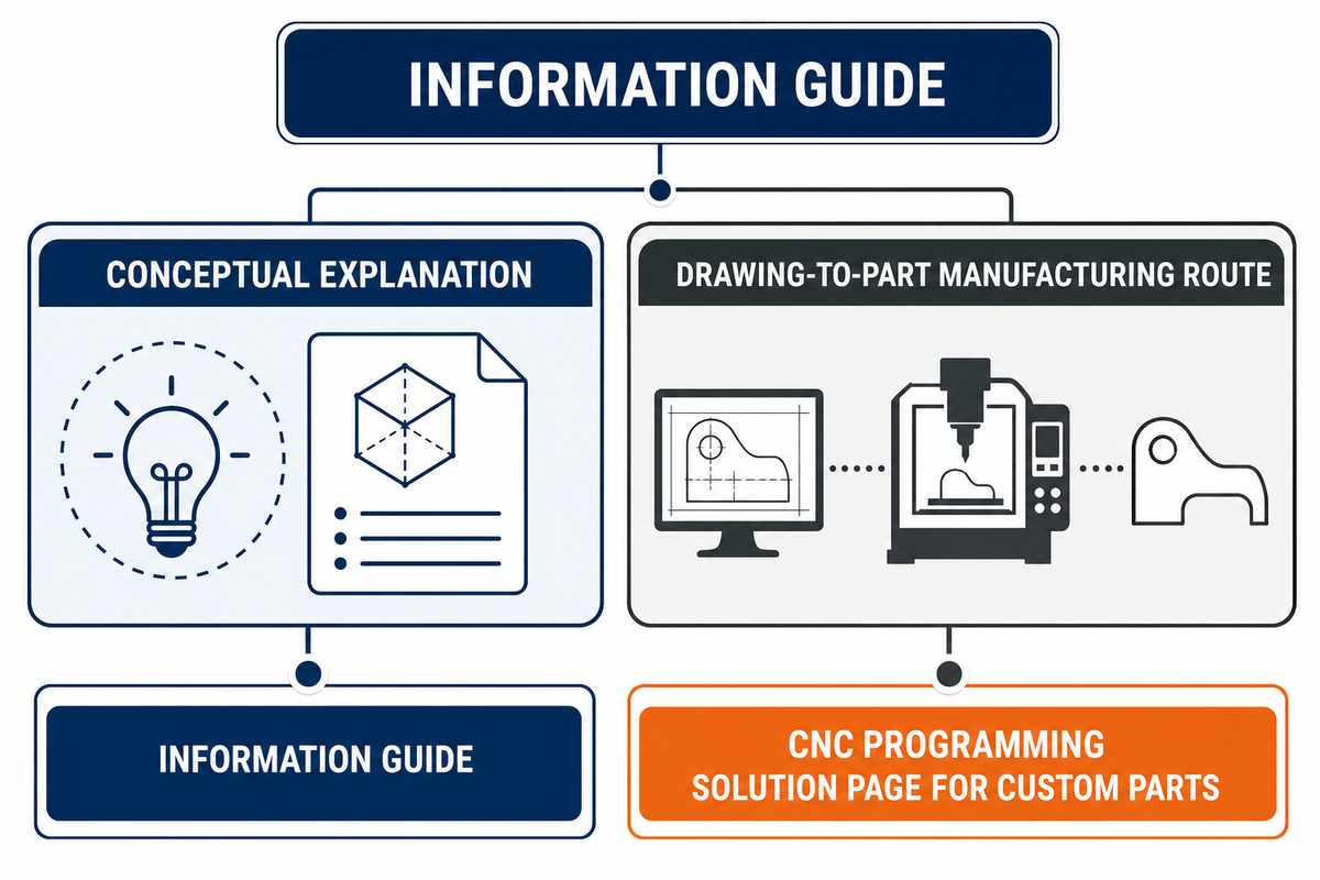
A conceptual explanation and a drawing-to-part manufacturing route require different information. Although related, these requests differ in what is required. For the latter, outside this guide’s scope, see Zhenling’s existing CNC Programming solution page for custom parts. This one route is shown for clarity of scope and is neither an availability nor outcome statement, certification, nor a statement of intended program release.
The NIST STEPNC++ publication distinguishes feature-based CAM information from CNC part-program output.
Frequently Asked Questions
What is CNC programming?
CNC programming is the work of translating manufacturing intent into instructions a CNC machine can interpret. That intent can include controlled design data, process decisions, coordinate and machine context, and controller-oriented output, not only code. In a conventional system, the program is one of many representations of a transaction of information. This guide explains that handoff conceptually; it does not provide controller code, release authorization, safety verification, or a shop-specific procedure. For a drawing-to-part manufacturing discussion, see Zhenling’s CNC programming solution for custom machined parts.
Can a CAD file directly create a CNC program?
A CAD file can provide essential geometry, but it does not automatically settle material, tolerance, datum, setup, tooling, machine, or revision context. For machine, work, tool, and drawing-reference frames, see Zhenling’s CNC Coordinate Systems. In many conventional workflows, CAM and post-processing help produce controller-oriented output; other information models may use a different route. The exact path depends on the manufacturing workflow and machine environment, so transferability and completeness should be checked rather than assumed from geometry alone.
What information should accompany a CAD model before machining?
Start with the current design definition, material and tolerance requirements, critical features, datum intent, relevant workholding or access limits, and revision context. It also helps to identify the source that governs any notes, interfaces, or functional surfaces that cannot be inferred from shape alone. The most suitable package will vary based on different parts and different steps in the process; in the absence of context, it is better to indicate the truth source than to provide a generic checklist, or even worse, to say that a single file contains everything.
What does a post processor do in CNC programming?
In a conventional workflow, it helps translate CAM-oriented information for a particular controller context. It does not resolve missing part definition, setup assumptions, or revision decisions.
Why can the same part need different machine context?
Axis arrangement, tool availability, workholding, accessible geometry, and control environment can change the relevant programming context. Transferability is conditional, so the comparable conditions should be checked rather than assumed.
Is G-code the same thing as CNC programming?
G-code is an important output language for many CNC environments, but CNC programming also involves the upstream manufacturing information that gives those instructions their intended meaning.
References & Sources
- NIST, STEPNC++: An Effective Tool for Feature-based CAM/CNC.
- ISO/TS 14649-201: Machine tool data for cutting processes.
- ISO 6983-1: Data format for numerical control systems.
- Open machining-data research describing geometry, NC code, and machine data.
- NIST, On-Machine Measurement Use Cases and Information for Machining Operations.
About this guide
Shanghai Zhenling Hardware Co., Ltd. provided the business context for this educational page. The article deliberately separates that commercial context from its technical discussion: it uses only the supplied first-party page for the single internal route and does not infer equipment availability, delivery terms, outcomes, or certifications beyond the material provided for this project.