


Updated October 2026
Quick Specs
Scope: machined-part drawing interpretation. Example units: millimeters. Check: drawing revision, individual limits, general notes and invoked standard. Teaching examples don’t establish supplier capability.
Engineering drawing tolerances dictate the allowed variation in the dimensions and geometry of a part. Read the specific callout, general notes and governing standard together: a size inside its limits passes the size check, while the part still needs the required geometric and inspection checks. For 25.00 ±0.05 mm, the lower limit is 24.95 mm, the upper limit is 25.05 mm and the total tolerance width is 0.10 mm.
Tolerances set a limit on allowable variation. Specific tolerances allow for real world deviation from perfect during production. Used numbers are original teaching aids. For a wider context of measurement, see our CNC metrology services.
Engineering drawing tolerances specify acceptable variation under the drawing’s governing rules. A 25.00 ±0.05 mm size permits 24.95–25.05 mm. Size conformity still needs the required geometric and inspection checks.
Key points
- ASME and ISO can relate size to form differently.
- Unequal bilateral deviations can shift limits without changing total width.
- Check assembly fit at the minimum and maximum clearance combinations, not only each part’s size limits.
- Inspection needs the specified characteristic and applicable decision rule.
Read the drawing before applying tolerances

When interpreting individual numbers on a drawing, account for the revision, unit and stated dimensioning standards first. These are fundamental principles of requirement control. Generally, a dimension line connects a dimension to the feature to which it applies. Look for local tolerance and read the general notes. A model, printed dimension or purchase specification may describe a revision differently. Resolve discrepancies before anyone programs, quotes or inspects the part.
What is tolerance in CAD drawing?
A tolerance in CAD specifies the allowed variation of a stated dimension or geometric requirement. Nominal (intended) models define the geometry and don’t necessarily show all acceptance limits. Dimensioned drawings, or properly defined models, must describe the applicable limits and/or general specifications, particularly in light of the stated standard and revision.
Check whether the released package uses a drawing, model-based definition or an agreed combination. The ASME Y14.5 public scope covers engineering-drawing and related-document interpretation. An untoleranced model diameter shouldn’t become an assumed shop acceptance limit. Likewise, center lines identify axes and hidden lines show obscured features; neither is a substitute for a complete feature requirement.
Common mistake: treating every dimension as an independent plus/minus requirement. A boxed basic dimension, a reference dimension and a toleranced size serve different purposes. Identify their notations and then apply the applicable defaults. If a note and a local callout appear to be inconsistent, send a question with a marked drawing to the designer, rather than deciding which number has more decimal places.
Read bilateral, unilateral and limit dimensions
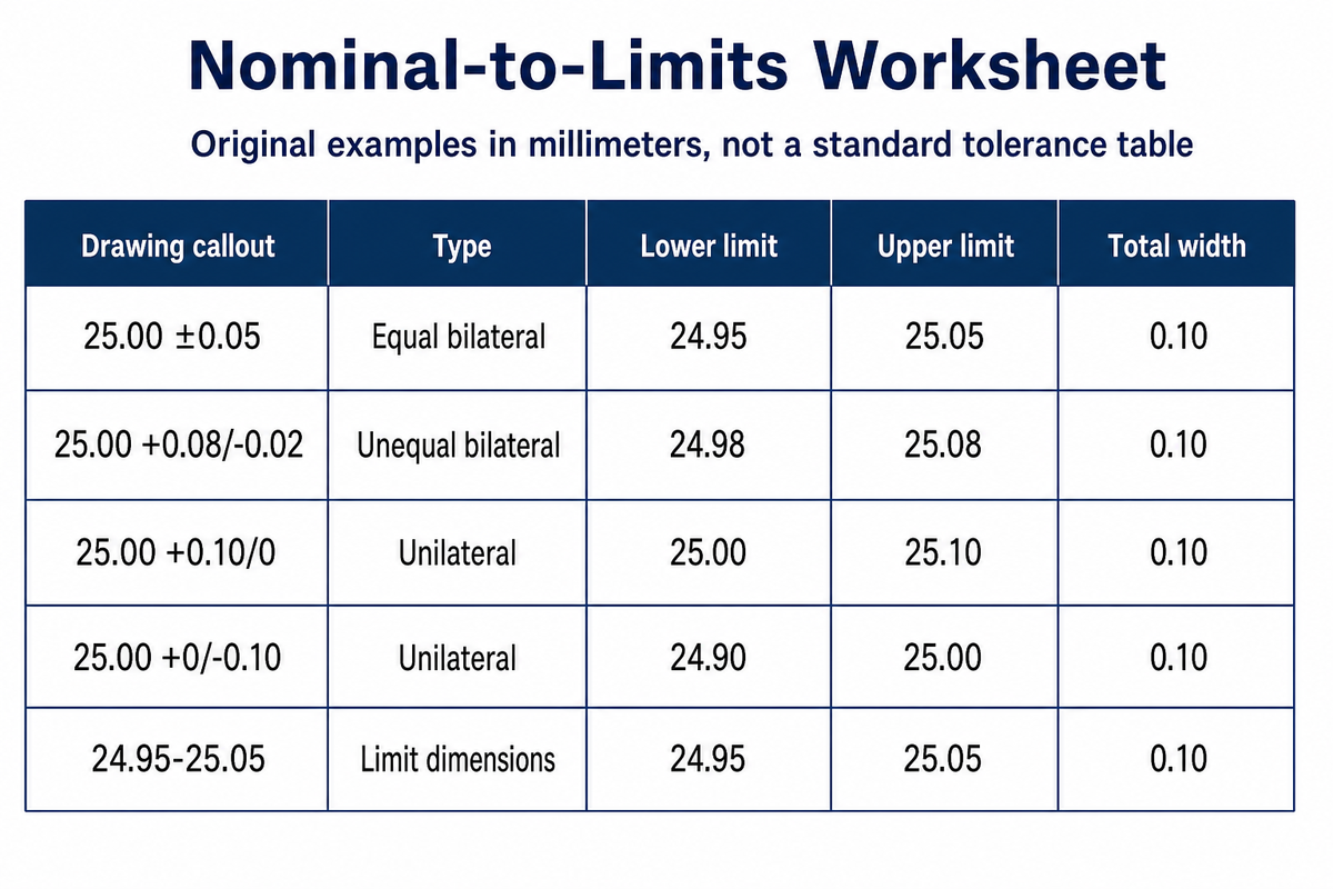
A bilateral tolerance allows variation on both sides of the stated value with equal or unequal deviations. A unilateral tolerance allows variation on only one side. Limit dimensions define the two end points of an interval. The total width of an interval is the larger limit minus the smaller limit. This allows certain variations in the dimensions.
Nominal-to-Limits Worksheet
The Nominal-to-Limits Worksheet helps to convert a size callout to limits before inspection.
| Drawing callout | Type | Lower limit | Upper limit | Total width |
|---|---|---|---|---|
| 25.00 ±0.05 | Equal bilateral | 24.95 | 25.05 | 0.10 |
| 25.00 +0.08/−0.02 | Unequal bilateral | 24.98 | 25.08 | 0.10 |
| 25.00 +0.10/0 | Unilateral | 25.00 | 25.10 | 0.10 |
| 25.00 +0/−0.10 | Unilateral | 24.90 | 25.00 | 0.10 |
| 24.95–25.05 | Limit dimensions | 24.95 | 25.05 | 0.10 |
For the first row, subtract 0.05 from 25.00 to get 24.95, then add 0.05 to 25.00 to get 25.05. Subtract these two limits to get 0.10. Notice that in the second row, the interval is shifted. It would be incorrect to say this is a unilateral case, as the limits cross the nominal value. Replacing this case with ±0.05 would shift both acceptance limits.
Imagine a quality engineer gets a “mock-up” drawing with the size of 25.00 ± 0.05 mm and a report with 25.04 mm. The size reported is within the stated interval. This is one check and not the end of the inspection. The engineer needs to have the correct feature, the drawing revision, the state of processing and the measurement definition. If the report measured a diameter before the specified surface treatment, it cannot simply be compared with a requirement intended for the finished feature. If the reported size is close to a limit, then the decision rule and uncertainty must also be considered. The worksheet will capture limits, and the inspection plan will describe how conformity is evaluated.
The NIST discussion of dimensional tolerances and uncertainty identifies a tolerance band and treats conformity judgment separately. Keep the inch or millimeter unit with the callout. A permissible deviation of ±0.05 isn’t a total band of 0.05, and it isn’t necessarily a 0.05 geometric tolerance zone.
Check limits and fits at both extremes
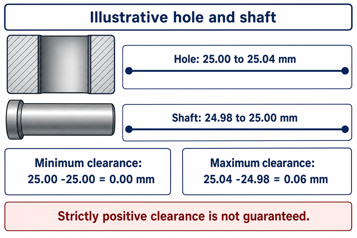
Evaluate two mating parts at the combinations that yield minimum and maximum clearance. For a hole and shaft, subtract the smallest shaft from the largest hole to get maximum clearance; for minimum clearance, subtract the largest shaft from the smallest hole. Checking a given mating relationship, termed as fit, helps ensure the limits selected support function. The calculations don’t verify the fulfillment of all geometric and surface requirements.
What is h6 and H7 tolerance?
H7 and h6 are classifications of holes and shafts in the ISO tolerance series. The letter denotes the position of tolerance zone relative to the basic size; the number denotes its grade. Their limits change with nominal size: for a 25 mm hole, H7 means 25.000 mm to 25.021 mm. You need the nominal-size range and applicable ISO tables to determine the actual deviations and size limits.
There is a published ISO 286-1 scope for the linear sizes of two parallel opposite surfaces and of cylinders. It uses terminology to describe fits without constraints of orientation or position. For fits, the scope of application of the standard must be consulted, and the limits for the specified tolerance class should be looked up using the nominal-size range and applicable edition. Do not read “h6” as ±0.006 mm, for example.
Consider an illustrative hole specified from 25.00 to 25.04 mm and a shaft from 24.98 to 25.00 mm. Minimum clearance is 25.00 −25.00 = 0.00 mm. Maximum clearance is 25.04 −24.98 = 0.06 mm. Both sizes may satisfy their individual limits, yet the drawing hasn’t guaranteed strictly positive clearance. If the design needs running clearance, the designer must choose a positive minimum margin and account for the relevant operating conditions. The purchaser can’t fix this by requesting “more accurate machining” while leaving the same size limits. Nor does the calculation address misalignment between the two features.
Depending upon the fit, the functional concern may be sliding, retention or alignment. A bearing and housing need their own specified mating requirements. Don’t assign a general allowance from an unrelated chart just because the nominal diameter matches.
Use general tolerance notes within their scope
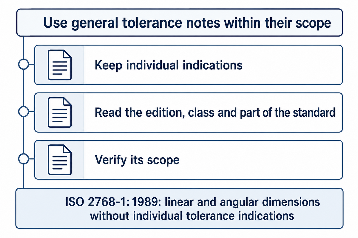
A general tolerance note applies if its referenced rules cover the feature and no individual indication gives the relevant requirement. Read the edition, class and part of the standard, and verify its scope. A local dimensional tolerance should not be replaced by a broad default, and the note, “ISO tolerance,” leaves too many unresolved interpretations.
ISO 2768-1:1989 addresses general tolerances for linear and angular dimensions without individual tolerance indications. Its abstract describes four classes and states that it is applicable to workpieces produced by metal removal or by forming from sheet metal. These scope statements do not make it a universal answer for casting, every fabrication process or every geometric requirement.
In an Eng-Tips discussion about drawing defaults, one participant cites a shop document problem, and readers discuss whether the drawing should stand on its own. A lesson here is to make invoked requirements accessible and stable. It’s an old discussion, and not an interpretation of current standards.
During the last review prior to release, verify which dimensions refer to the general note and which have specific limits. Parts within drawing tolerances still require the other applicable checks. Determine whether every dimension that needs an acceptance requirement has one via the rules of the drawing. Don’t default to a decimal place just because another customer’s title block says so. When a critical interface requires something different, assign tolerances explicitly, and have the designer approve the change.
Read size and geometry under the stated standard
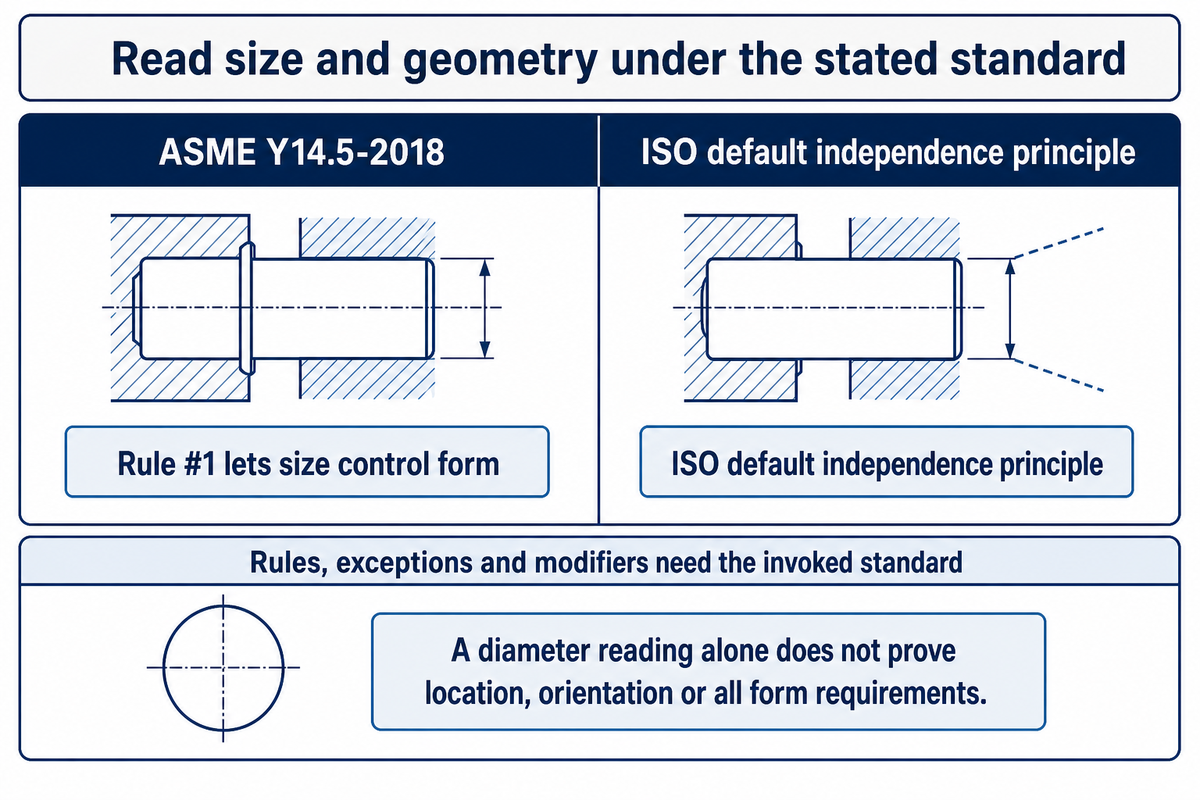
Read size and limiting dimensions and geometric controls as part of the same specification, and apply relationships of the governing standard to them. A diameter reading alone does not prove location, orientation or all form requirements. However, it is also wrong to say that size and form are always independent across ISO and ASME drawing systems.
The ASME course on Y14.5-2018 explains that Rule #1 lets size control form and contrasts this with the ISO default independence principle. The applied rules, exceptions and modifiers need the invoked standard. Do not use a short cut from one dimensioning system to another.
Geometric dimensioning and tolerancing uses a feature control frame to state the control, tolerance zone and relevant references. Position may relate a feature to datums; flatness controls a surface’s form. Passing a two-point diameter check doesn’t replace these evaluations. Our GD&T symbols and basics covers these symbols and the reading sequence.
Common mistake: adding the title-block size tolerance to a boxed basic dimension. Goodwin University’s teaching article states that a basic dimension defines the geometry of which the permitted variation is controlled by the associated geometric specification. It also distinguishes the linear width of a geometric angularity zone from an angular dimension’s deviation in degrees. It suggests reading the symbol and units before doing calculations.
If a datum feature is hard to access after assembly, raise that issue before manufacture. Raising this after manufacture may result in a different fixture reference that is not necessarily an equivalent datum scheme.
Choose tolerances from fit and function

Select the required quality using the interface’s function, then confirm the manufacturing process and inspection route can support the requirement. Tighter tolerances can change tooling, setup, measurement and rework needs. These should solve a particular problem rather than act as a general signal that a drawing is precise.
A surface that allows assembly movement may require a different limit than that of a locating interface. The ISO 286 fit-system scope addresses sizes of mating features and not every performance requirement. Analyze the required degree of accuracy feature by feature. This supports a cost effective manner of specifying parts without weakening a functional requirement.
Suppose a design engineer asks for an extremely tight requirement on an exposed cosmetic edge of a bracket because the mating bore requires tight tolerances. The procurement team gets quotes with different inspection assumptions. A manufacturing engineer asks which surfaces of the bracket locate it, and the design engineer confirms the exposed edge has no effect on assembly position. The discussion is now specific. Functional requirements of the bore and datum must be retained. The edge may be unnecessarily tight, and it may be changed only with design approval. The finance team can now compare quotes against the same requirements. There’s no need to guarantee a certain percent savings to remove a requirement with no identified function.
This makes cost and performance a feature level decision. Ask the supplier to identify doubtful features prior to an order, and ask quality control to explain how those features will be evaluated. A claimed machine positioning accuracy doesn’t mean all features will be within limits. Confirm the machine tools, workholding and inspection route for the work piece.
Agree how inspection will judge the result
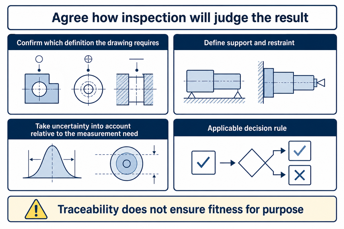
Inspecting features requires more information than an upper and lower size. Provide definitions for the measured characteristic, part condition, datum setup, measurement method, reporting scope and applicable conformity decision rules. Comply with the requirements of the invoked standard and the contract prior to accepting any additional agreement. A readable display or a calibration certificate alone won’t settle conformity for measurement results near specification limits.
“Neither organizations nor laboratories can be traceable. Only measurement results can be traceable.”
NIST states that traceability does not ensure fitness for purpose. Take uncertainty into account relative to the measurement need. The current public ISO 14253-1:2017 scope covers conformity verification for relevant geometrical product specifications, including results near limits and the effect of measurement uncertainty. This does not mean a free pass to use whatever acceptance rule that gives a go/no go outcome.
Define “diameter” carefully. NIST’s size-tolerancing research distinguishes two-point and associated size definitions. A two-point result and a least-squares fitted diameter do not necessarily represent the same characteristic. ISO 14405-1:2025 provides linear-size specification operators; confirm which definition the drawing requires before comparing reports.
Common mistake: A very common mistake is measuring the length or diameter in a convenient, clamped state when the requirement concerns another state. For a flexible feature, define support and restraint instead of allowing the fixture to hide distortion. See free-state versus constrained inspection for that.
When results are at boundary limits, use the established rule and the associated uncertainty. Our measurement uncertainty near a tolerance limit guide presents this. Keep instrument resolution separate from measurement suitability; a higher number of displayed digits doesn’t mean a better measurement.
Send a drawing release packet for comparable quotes

The same released requirements should be sent to all suppliers and the same inspection deliverables requested. A low price per unit is difficult to compare when one quote includes a different revision, manufacturing state or report scope. The Drawing Release Packet below ties design decisions to evidence and an owner prior to production, thereby turning unresolved assumptions into questions.
Drawing Release Packet
The Drawing Release Packet captures controlled requirements, inspection evidence, and decision owners before a supplier quote is issued.
| Item | Example instruction | Owner and confirmation |
|---|---|---|
| Controlled documents | PDF drawing and STEP model, both revision C; resolve discrepancies before machining | Design engineer identifies governing definition |
| Quantity and scope | Quote 100 finished brackets against the same material and treatment specification | Procurement checks identical scope |
| Critical size | Identify the 25.00 ±0.05 mm feature; limits 24.95–25.05 mm | Design approves function; supplier confirms feasibility |
| General note | Record the exact invoked part, edition and class; keep individual callouts | Design resolves incomplete references |
| Inspection state | Confirm whether the requirement applies before or after treatment and under what support | Quality engineer records the agreed state |
| Geometric evaluation | Use the drawing’s datum scheme, modifiers and applicable size/form rules | Quality and manufacturing confirm access/setup |
| Report and release | Identify required measured results, sampling and release records; flag boundary results under the applicable rule | Quality defines evidence; procurement prices that scope |
| Exceptions | List proposed deviations separately; no silent substitution in the quote | Design approves changes before order release |
In this case, one supplier quotes a size check on the critical feature and the other includes the geometric evaluation and the requested report. The two prices aren’t comparable yet, because the deliverables differ. Procurement returns the same packet to both suppliers. Quality confirms the scope of the report, Manufacturing checks whether the datum features remain accessible, and Design closes the size-definition question. Finance then compares prices for the same accepted output. This also makes a rejected lot easier to investigate: the team is able to distinguish a deviation in manufacturing from an undocumented change in measurement or release requirements.
Quality’s measurement-reporting discussion distinguishes report formats, but reporting alone doesn’t establish a suitable measurement method. Specify both: NIST’s fitness-for-purpose boundary is about the measurement need. Also distinguish first article versus first piece inspection when requesting release records.
Zhenling Metal’s published drawing-based service information lists accepted model/drawing formats and an ISO 2768-m default unless the drawing states otherwise. Send the actual requirements for review; do not infer approval of a particular tight feature from that general statement.
Industry outlook: update standard notes without changing design intent
Practical issues arise during implementation regarding revision control. Withdrawal of a document or publication of a new edition may result in a drawn note being inherited with ambiguity. Revision of a reference should preserve the intended fit and function through an engineering review, as the same requirement may not be reflected in a more current number. Ensure the referenced standard is checked before releasing a new quote or a revised drawing.
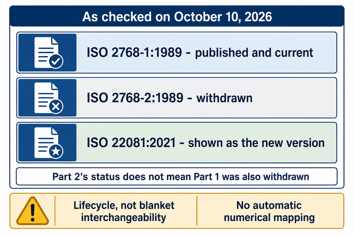
As checked on October 10, 2026, ISO’s catalogue still lists ISO 2768-1:1989 as published and current following its 2022 confirmation, while indicating a replacement is being developed. In contrast, ISO 2768-2:1989 is withdrawn, with ISO 22081:2021 shown as the new version. The latter was confirmed in 2026. Part 2’s status does not mean Part 1 was also withdrawn.
Do not convert a legacy K class into an ISO 22081 requirement simply by changing the label. The public ISO 22081 abstract expressly excludes links to general specifications defined in other standards; it supplies no automatic numerical mapping. Review the actual adopted documents and define the needed specifications on the drawing. A successor listing establishes lifecycle, not blanket interchangeability.
Another relevant change is ISO 14405-1:2025 for linear sizes. Its public scope distinguishes default and special specification operators, reinforcing why a size definition belongs in the interpretation review. For ASME drawings, the publisher lists Y14.5-2018 (R2024); customer drawings can still invoke an earlier edition, so use the edition the drawing or contract names.
If the order changes, have design identify the features that are changed, quality compare the evaluation requirements, and procurement send the same revision to each bidder. Keep the formerly approved revision with the change record to assist the team to explain the revision. If the review finds there’s no functional change, then note that conclusion. If there’s a functional change, then revise the callout and inspection plan. This is more effective than adding a current year to the title block while leaving the requirement uncertain.
Frequently asked questions
What are the four main types of tolerances in engineering?
For a machined-part drawing, four useful groups are size tolerances, limits and fits, general tolerance notes and geometric tolerances.
For reading a machined-part drawing, four useful groups are individual size tolerances, limits and fits, general tolerance specifications, and geometric tolerances. Bilateral and unilateral are ways to express size variation within the first group. They aren’t substitutes for form, orientation or position requirements. Use the drawing’s stated standard to interpret the actual controls. A local size callout must be read alongside any geometric controls and the invoked general note; each answers a different inspection question.
What are form tolerances?
Form tolerances control a feature’s shape, such as a surface’s flatness, rather than merely its size or position.
A flatness requirement concerns the specified surface itself; it differs from parallelism, which relates orientation to a datum. Read the feature control frame and the governing standard, including any applicable relationship between size and form. Don’t assume that several acceptable local size readings prove the entire shape requirement. The governing rules can also relate size to form, so identify the drawing system before deciding which separate checks are necessary.
What is the ASME standard for drawings?
For dimensioning and tolerancing, the ASME standard is Y14.5.
ASME’s public catalogue lists Y14.5-2018 (R2024) as remaining in effect after reaffirmation. The broader Y14 family covers other drawing and product-definition subjects, so Y14.5 alone isn’t a complete specification for every documentation task. Use the edition invoked by the drawing or contract and resolve missing or conflicting references before manufacture. Missing edition information is a document-control question for the designer and customer, rather than a decision for the machine operator alone.
What does “nominal” mean when discussing a tolerance on a technical drawing?
Nominal describes the stated reference or target size.
The permitted limits depend on the specified deviations. A nominal value isn’t automatically a boxed basic dimension, and it need not sit at the interval’s midpoint.
Can engineering drawing tolerances be adjusted?
Yes, through an approved design change that preserves the needed function and updates the controlled documents.
A supplier may propose a different limit because of feature geometry, tooling or inspection difficulty, but the proposal isn’t permission to manufacture to it.
Record the affected feature, proposed limits, reason and assembly consequence. Have design review the fit, quality confirm how it will be inspected, and procurement check the revised scope with each supplier. Update the drawing, model, purchase requirements and inspection plan together where applicable. For an existing order, identify which revision governs the parts already made and which governs subsequent production. A report showing a result outside the original limits can’t become a conforming result merely because the drawing was edited afterward; disposition of those parts needs its own authorized decision.
Can you explain the difference between tolerance and dimension in engineering drawing?
A dimension states a size, distance or other geometric value.
A tolerance states the permitted variation for the specified characteristic. In the illustrative 25.00 ±0.05 mm callout, 25.00 mm is the stated size and 24.95–25.05 mm is the permitted interval. Geometry, measurement definition and applicable acceptance rules still determine how the feature is evaluated.
Key takeaway
Convert the callout to limits, check assembly extremes, and release the same drawing and inspection requirements to every supplier.
Review dimensional inspection requirements on Zhenling Metal’s metrology service page before sending your controlled drawing and model for quotation.
References & Sources
- National Institute of Standards and Technology: uncertainty and dimensional measurements, NISTIR 5170 (1993)
- ISO 286-1:2010: public fit-system scope and lifecycle
- ISO 2768-1:1989: public general-tolerance scope and status
- ISO 2768-2:1989: withdrawn status and ISO 22081:2021: public scope and status
- ASME Y14.5 public catalogue and ASME size/form teaching outline
- Goodwin University: common drawing-interpretation mistakes
- NIST: metrological traceability and size-tolerancing research abstract
- ISO 14253-1:2017: public conformity-decision scope and ISO 14405-1:2025: public linear-size scope
- Quality: measurement data reporting
Standard references cited above relate to public publisher scopes and lifecycle information. Use the actual documents of standards applied on your drawing. Examples and release packets are to help explain and interpret the documents, not replacements for those documents.



