Design & Inspection Guide
Translate thermal, grounding, finish, fit, and cleanliness needs into a part package that a machine shop can quote, manufacture, and inspect.
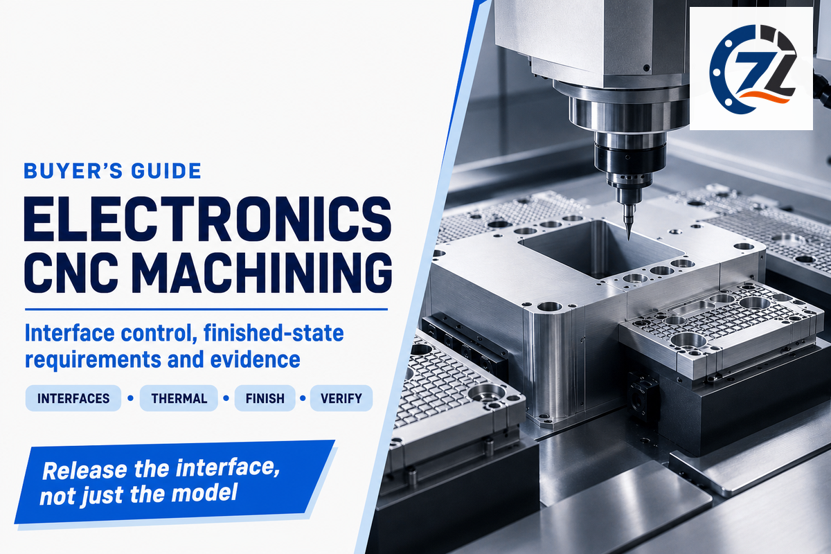
Electronics CNC machining isn’t difficult because every enclosure or heat sink needs an extreme tolerance. Electronics CNC machining is the computer-controlled removal of material to create drawing-defined hardware around electronic assemblies. It’s difficult because several interfaces must work at once. A housing can pass dimensional inspection and still disappoint after anodizing, assembly, thermal loading, or EMC testing.
This guide shows design, quality, and procurement teams how to define those interfaces without turning a drawing into a blanket list of tight dimensions. The emphasis is on machined housings, chassis, brackets, heat sinks, connector features, fixtures, and related electronic components. This document does not replace product-level thermal, ingress, safety, or EMC validation.
In electronics manufacturing, machining for electronics is one of several routes to hardware fabrication around printed circuit boards and other electronic devices. CNC machining for electronics is very applicable during prototype work and controlled design changes, while consumer electronics or other stable-volume programs may also compare forming, extrusion, casting, and additive manufacturing.
The key advantage of precision machining is not simply that a CNC milling machine can machine complex shapes. Precision CNC work becomes useful when the electronics industry converts assembly needs into inspectable features, and when the manufacturing process preserves repeatability from the first electronic part to later lots.
Start With Interfaces, Not a Generic “Precision Part” Brief
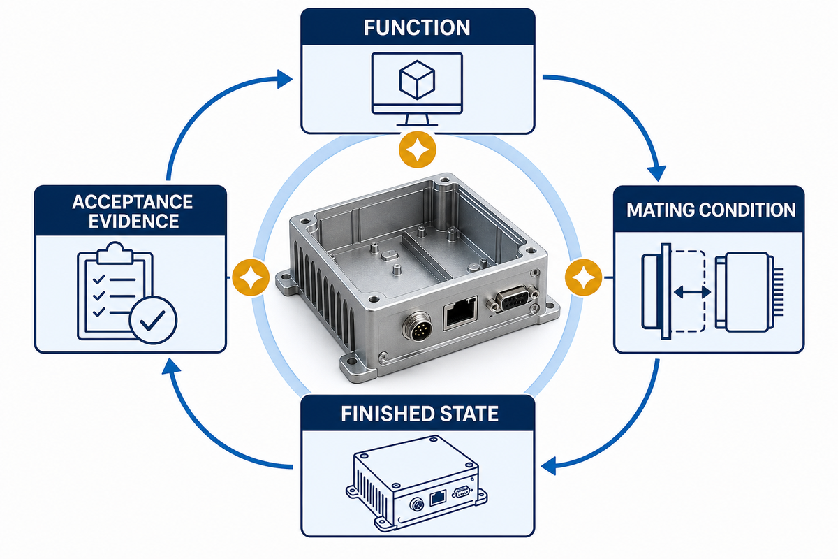
An example such as “aluminum electronics enclosure, high precision” leaves the supplier to guess what’s important. Identify where the part transfers heat, carries current, locates a circuit board, supports a connector, compresses a seal, or presents a visible surface.
Good electronics machining therefore connects design and manufacturing decisions. Modern electronics may require precise connector alignment, thermal contact and clean internal spaces, but the words high-precision CNC don’t tell which feature controls the function. The drawing needs to do that.
Then divide the evidence. A CNC machine and its inspection process can demonstrate material identity, geometry, edge condition, surface treatment zones, and specified characteristics. By themselves, they can’t prove the final device’s EMC, ingress protection, or thermal performance. Those outcomes depend on the complete configuration, including fasteners, gaskets, interface materials, openings, cable entries, and assembly load. For the part-level side of that evidence split, NIST’s metrological traceability guidance explains why a measurement result needs a documented chain to a stated reference.
Use the Five-Zone Interface Map
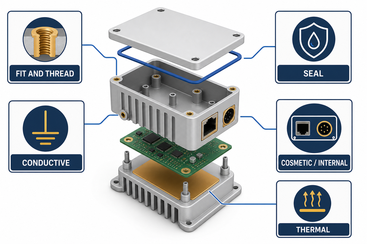
The Five-Zone Interface Map is an editorial design-review framework, not an industry standard. The table separates five functional zone families from four supporting release controls for thread, datum, edge, and packaging or cleanliness. Mark each zone on the drawing or a controlled supplemental sheet, then assign its finished-state requirement. Where a zone carries a measurable requirement, use NIST’s traceability framework to specify the reference and calibration chain behind the reported result.
| Interface category | Typical function | Define before RFQ |
|---|---|---|
| Thermal | Heat transfer to a device, plate, or sink | Contact area, flatness or profile control, texture, finish state, test stage |
| Conductive | Grounding, bonding, shielding continuity | Mask boundary, contact geometry, fastener path, continuity check |
| Fit and thread | Connector, PCB, cover, insert, or mating part | Datums, tolerance, gauge or method, before/after-finish state |
| Seal | Gasket support and compression path | Land geometry, edge condition, surface requirement, assembled test owner |
| Cosmetic/internal | Visible appearance or protected internal cavity | Finish class, visual limit, burr and cleanliness criteria, packaging |
| Thread | Fastener preload or insert retention | Thread class, coating state, gauge, depth, and insert requirement |
| Datum | Repeatable assembly and measurement setup | Datum feature, order, accessibility, and finished-state condition |
| Edge | Handling, wire protection, and mating clearance | Burr prohibition, edge break, protected sharp edge, and inspection method |
| Packaging | Protection of clean and cosmetic surfaces | Cleaning state, separators, plugs, wrap, label, and transport orientation |
This tool resolves a conflict that’s common in design and reviews. For example, a note on a drawing to apply a coating on an entire part may affect an electrical contact area. An unspecified masking line may lead to a dimensional and visual conflict.
Across the wider manufacturing industry, CNC machining in electronics can cover very different electronics applications. The five-zone view keeps complex electronic components from being treated as generic machine parts, and it gives electronics manufacturers a common language for engineering and supplier review.
Choose Material and Condition From Functional Requirements
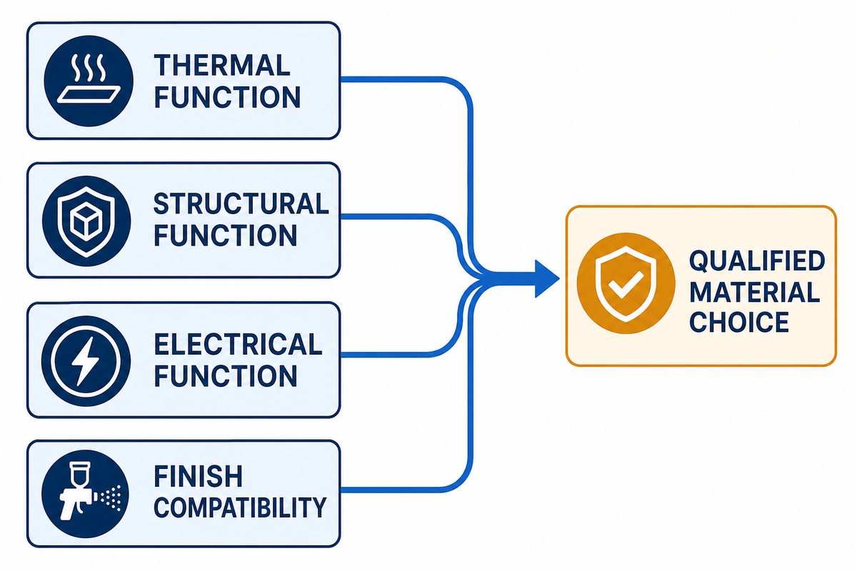
“Aluminum” isn’t a complete material specification. Identify the alloy and condition using an accepted designation, then connect that choice to thermal behavior, conductivity, strength, corrosion exposure, mass, machining response, finishing, and supply. The Aluminum Association publishes designation and product standards that can support this definition.
For steels, stainless steels, nickel alloys, and engineering plastic parts, use the same discipline: name the grade, condition, and any certificate or traceability requirement. Don’t blindly copy a material from the last design because it has similar geometry.
A broad range of materials is not the same as a qualified material choice. Different CNC machining processes and machining methods can expose different workholding, tool-access, heat, and finish constraints, so a machining partner should confirm the proposed route against the released specification.
Zhenling Metal’s public company scope includes drawing-defined non-standard parts in aluminum, steel, stainless steel, and nickel-alloy families. Copper machining should be confirmed in writing rather than assumed, and every project-specific material or process capability belongs in the quotation.
Design Thermal Faces and Heat-Sink Features for Measurable Contact
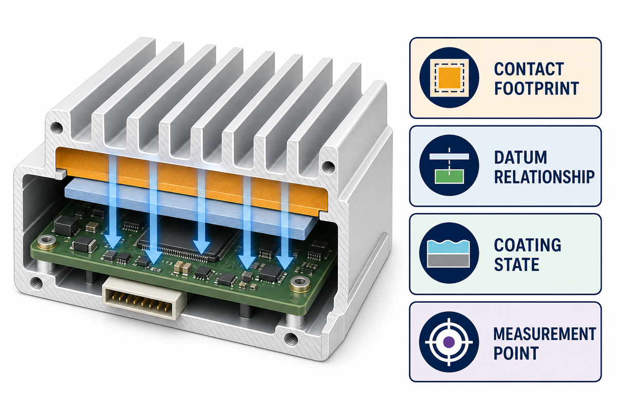
Thermal management begins at the real interface, not at a general surface-finish callout. Define the contact footprint, datum relationship, permitted shape error, texture parameter, state of coating or masking, and the point of surface measurement. Consider cutter access, fin aspect ratio, wall movement and the path of deburring for heat sinks.
Multi-axis machines and high-speed cutting may give better access in appropriate locations, but neither term provides evidence of the finished interface. Acceptance ultimately rests on the specified surface and evidence of measurement, even when advanced CNC and modern CNC controls support process execution.
Contact conductance is affected by the real area of contact and contact pressure. A small, uniformly loaded coupon can’t always be taken as representing a large perimeter-fastened enclosure because the bolt pattern, housing stiffness, interface material, and central gap can affect the load distribution, as NASA’s bounded electronics-box study illustrates.
Indicate whether acceptance applies only to the initial assembled condition or to a specified service exposure. If cycling or aging is applicable, document the interface condition and performance before and after such a test. Make sure the shop’s dimensional part evidence is distinguished from a buyer- or lab-owned assembled thermal test.
Protect EMI, Grounding, and Conductive Contact Paths
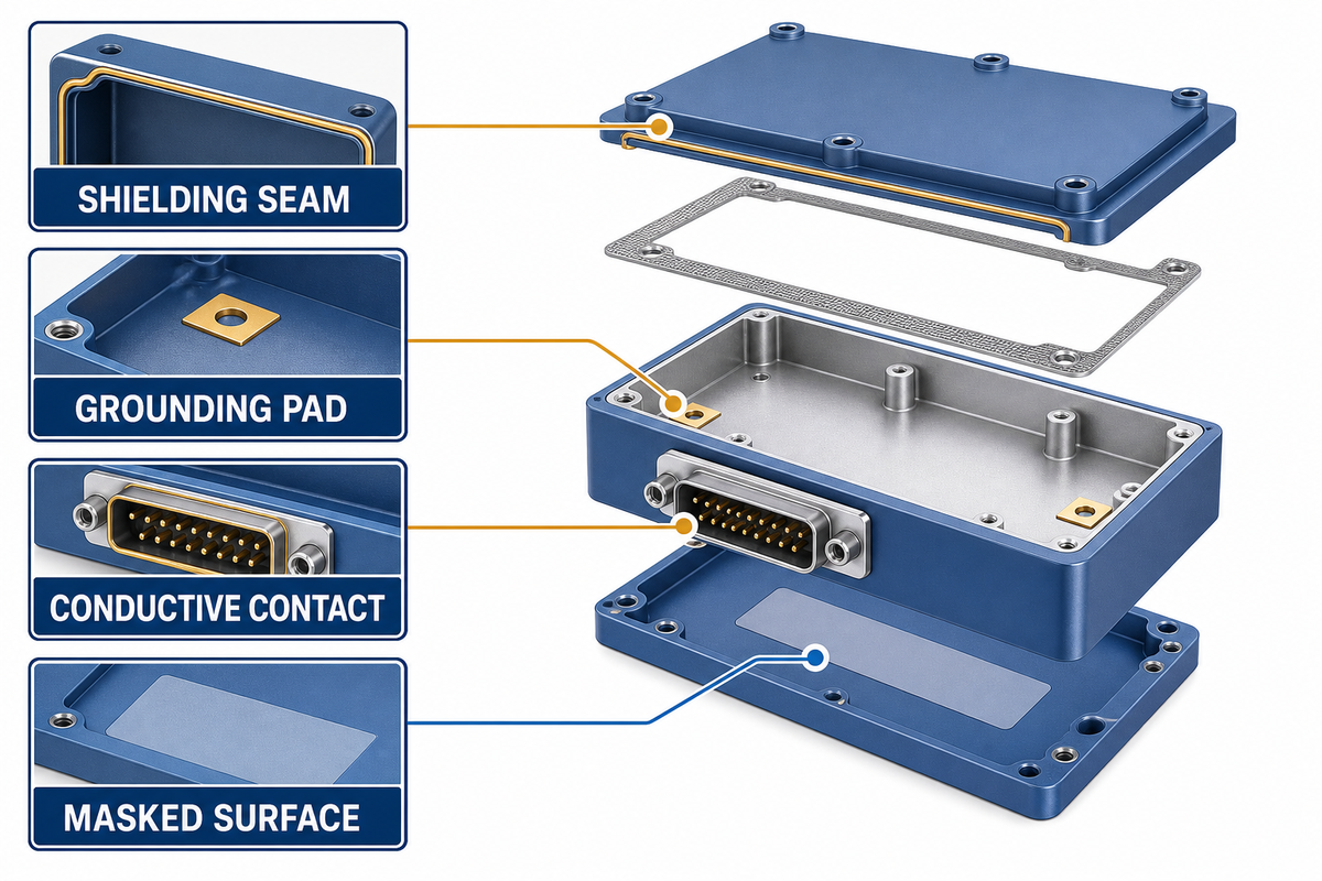
A metal box alone doesn’t establish a proven shield. Assembled results can depend on seams, apertures, joints, connectors, gaskets, and grounding paths, to name a few. The drawing should control the features to establish the intended design, and EMC validation is the responsibility of the relevant product team.
This distinction holds throughout the electronics sector: CNC technology creates the hardware, whereas the assembled product is the final result. CNC machining technology doesn’t constitute a component-level continuity test equivalent to a complete enclosure shielding test.
Map conductive contact zones before anodizing, paint, or plating. State whether the area is masked, selectively treated, or accepted by another defined method. Include the mask boundary and finished-state dimensions where coating buildup could affect a connector, thread, cover, or bonding surface. An anodized oxide layer shouldn’t be assumed to provide the same electrical contact as bare aluminum.
Map Finishes Before Releasing Dimensions
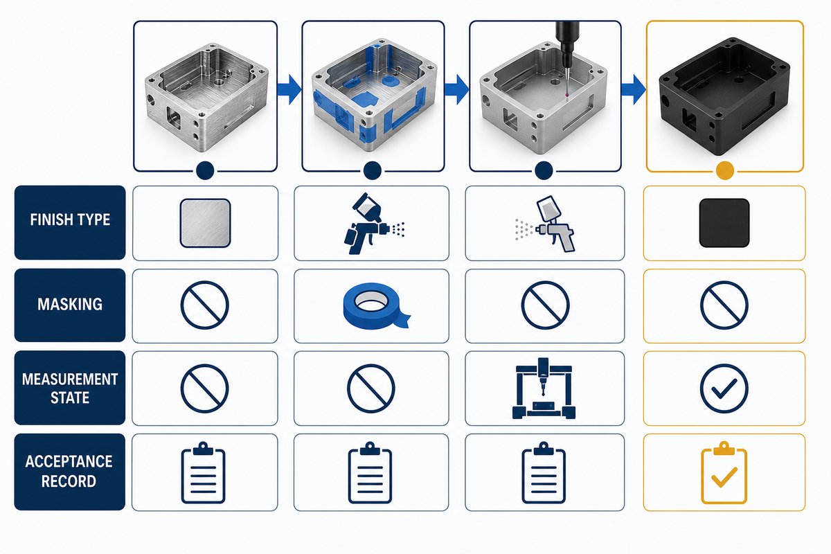
Finishes, tolerances and product specifications are determined at the time of product design. Finish requirements belong in the geometry review, not at the end of purchasing. For each controlled dimension, ask the following questions: is the dimension coated? Is the dimension required before or after coating? How will the dimension be evaluated? The evaluation record should also identify the measurement reference and calibration chain, consistent with NIST’s definition of metrological traceability.
- Specify the type of finish, the color and/or appearance class, and the controlling specification.
- Show masked and conductive zones with unambiguous boundaries.
- Define finished-state fits, threads, sealing lands, and connector openings.
- Agree to acceptable locations for racks, contacts, and witnesses, as appropriate.
- Use approved samples only when their status, revision, and acceptance role are controlled.
A process allowance shouldn’t be inserted in a generic manner. Buildup and dimensional effects depend on the selected process, alloy, geometry and other factors.
That is why electronic parts machining should coordinate machining, masking, finishing, and final inspection as one controlled fabrication sequence. A high-quality CNC result is judged in the required finished state. It isn’t judged when the bare metal leaves the mill.
Control Thin Walls, Fins, Burrs, and Contamination
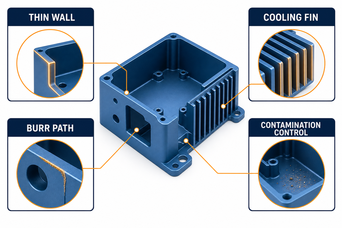
Thin walls and closely spaced fins can move during stock removal, clamping, heating and release from the fixture. Account for the feature with respect to the material, tool access, workholding and inspection. For complex features that need dimensional evidence, NIST’s dimensional-measurement publication explains that comparable results require traceability and an uncertainty statement; it does not require CT for every part. A prototype made slowly from one stock condition doesn’t, by itself, establish a stable mass production process.
The same applies when automation is introduced into electronics production. Automation can improve handling consistency, but it cannot correct an unstable machining process or an ambiguous edge requirement.
Edge requirements should be more descriptive than “deburr”. Define prohibited burrs, an edge break or radius where functionally required, and any other sharp-edge requirements. For internal features, define the cleanliness state and packaging required to keep chips or debris away from electronic hardware during assembly.
Apply Functional Tolerances and a Stable Datum Scheme
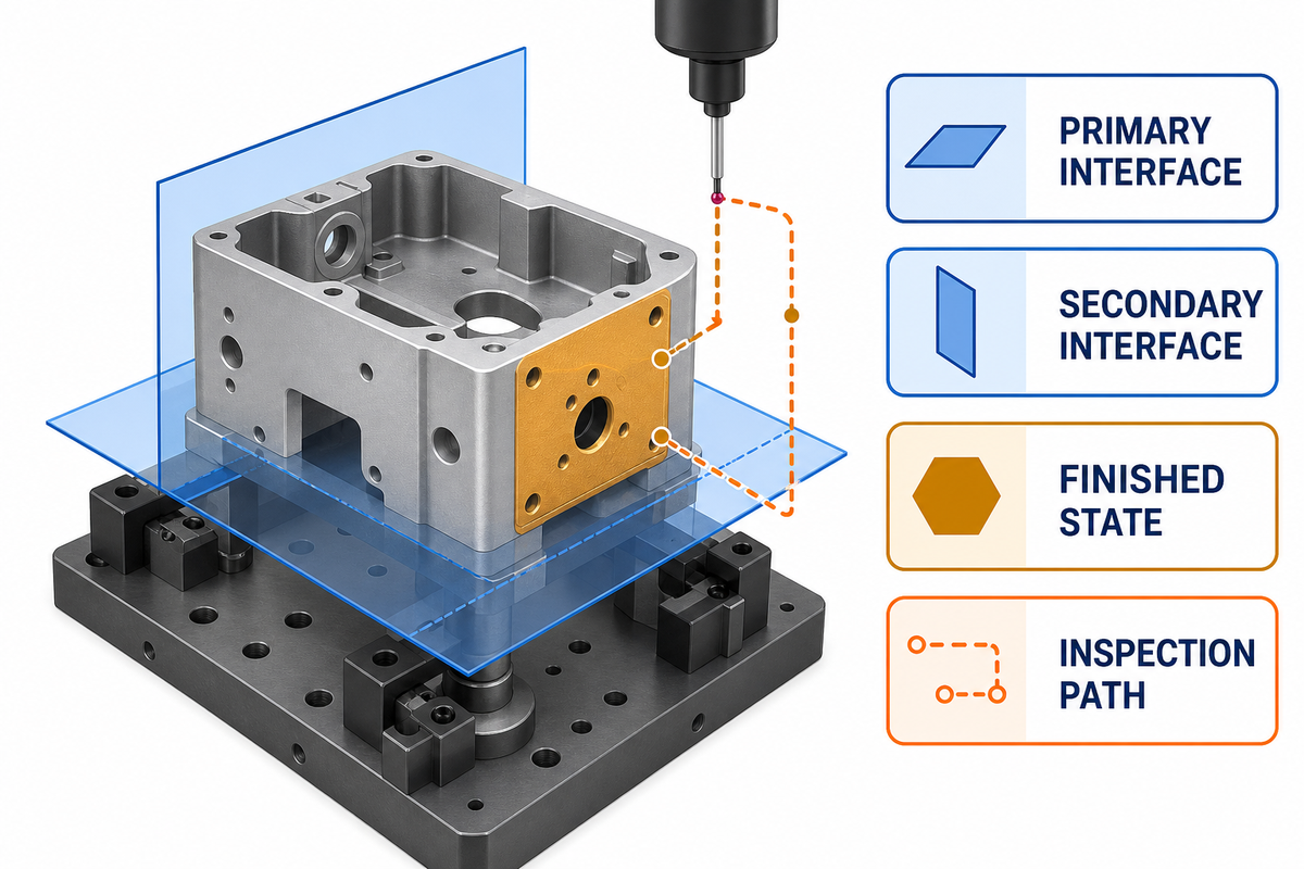
Restrict tight control where the assembly deserves it: at the connector position, board location, mating alignment, sealing lands, threaded interfaces, and thermal contact surfaces. A blanket tight tolerance increases inspection and manufacturing burden without guaranteeing better function.
Select datums that reproduce how the component is located in the real assembly. Provide the means of measurement, measurement stage, and acceptance criteria for each critical characteristic relative to these datums. Whether the method uses a gauge, optical system, CMM, or dimensional CT, the record should identify the part, revision, result, measurement stage, and method. If the measurement process isn’t direct and metrological traceability is required, note the stated reference and documented calibration chain in the record. The record should identify the measurement process and the equipment used. NIST describes metrological traceability as a documented, unbroken calibration chain, rather than simply owning calibrated devices.
Controls for selected datums illustrate one of the advantages of CNC machining: a released datum scheme ties manufacturing and inspection activities together. They also illustrate the rationale for “precision CNC machining” not being a full acceptance statement.
Choose Machining, Sheet Metal, Extrusion, or Casting
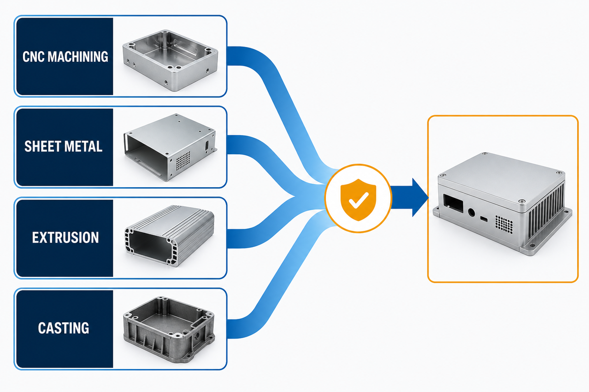
CNC milling lends itself well to low-tooling prototypes for design changes, complex pockets, and precise interfaces. It isn’t always the best route for every electronics housing. Sheet metal can suit bent thin-wall chassis; extrusion can suit repeatable linear heat-sink profiles; casting can become relevant when geometry and sustained volume justify tooling.
Expanded feasible geometry and process monitoring in the evolution of CNC machining are valuable, but the applications of CNC machining still require a functional and economical screen. In many projects, CNC machining plays its strongest role where revisions, integrated features, and measurable interfaces matter more than a universal volume claim.
CNC machining supports electronics development by shortening the path from controlled model to inspectable prototype. For established electronics production, however, CNC machining solutions should be compared to other routes, using the same requirements for the finished part.
Tooling cost and quantity should inform the choice, not serve as a universal break-even rule. Compare technical feasibility, material, tolerance, surface quality, secondary operations, schedule, change risk, supply resilience, and the supplier’s demonstrated process window. For a structured comparison, use the enclosure route comparator. A hybrid design may be stronger than forcing a process to achieve every feature.
Build the Finished-State Evidence Ladder
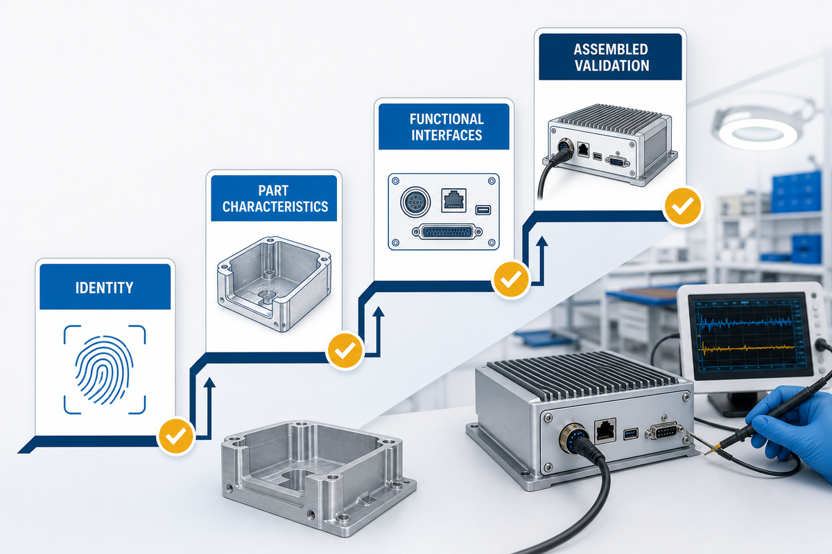
The Finished-State Evidence Ladder is this guide’s acceptance framework for preventing dimensional reports from being misused as proof of assembled outcomes.
- Identity: part number, revision, material, condition, quantity, and traceability.
- Part characteristics: Named dimensions, datum relationships, finish zones, edge condition, and cleanliness.
- Functional interfaces: Contact face, fit, thread, continuity and other drawing-defined checks.
- Assembled validation: Thermal, EMC and other environmental conditioning, ingress and load tests, and fatigue and durability (lifecycle) tests in a ‘representative configuration’.
Assign an owner and acceptance record at every level. The enclosure interface review can help expose missing ownership before release. For assembled tests, state whether the fixture represents the real load path and whether the evidence covers only the initial state or also specified cycling. First article inspection is useful for checking the first production realization against controlled requirements, but it isn’t a substitute for ongoing process controls or system validation.
Send an Interface-Controlled RFQ Package
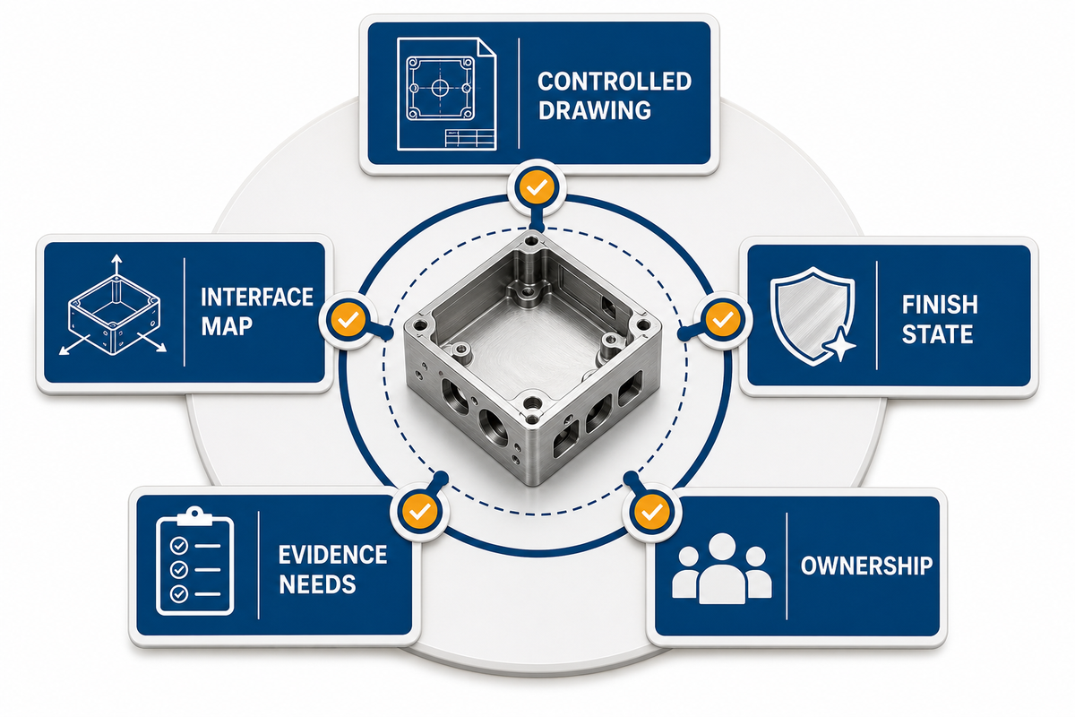
The Interface-Controlled RFQ pack is a tailoring checklist, not a universal legal requirement. Provide only required information related to quotation, manufacture or acceptance and distinguish a Request for Quotation (RFQ) from the final binding purchase and acceptance documents.
When teams are purchasing precision machining for electronics, the pack makes assumptions visible before price comparison. It also prevents “electronics CNC” or “complex electronic” from becoming vague substitutes for controlled models, drawings and acceptance plans.
- Hierarchy of controlled 3D models and drawings, with revision and part numbers.
- Material, condition, certificates, and traceability level
- Five-zone map with finish and mask boundaries
- Critical characteristics, datums, methods, stage, and sampling
- First-off or first-article expectations and deviation process
- Quantity, prototype-to-production plan, destination, and requested date
- Cleaning, preservation, packaging, labeling, and required records
For a project-specific assessment, please provide the controlled package rather than a screenshot or standalone model. The evidence record provided by the browser-based electronics RFQ is copy-ready. Review Zhenling Metal’s electronics CNC machining service, then request a drawing review and quotation.
Frequently Asked Questions
What is electronics CNC machining?
Electronics CNC machining is the computer-controlled removal of material to produce drawing-defined housings, heat sinks, brackets, connector features, fixtures, and other hardware used around electronic assemblies. Part inspection can verify specified material, geometry, and finish; system thermal, EMC, ingress, and fit outcomes require separately assigned validation.
Which material is best for a CNC-machined electronics enclosure?
The best material is the alloy or grade, in a stated condition, that meets the enclosure’s needs together. Consider thermal, electrical, corrosion, mass, strength, magnetic, finishing and supply needs, determine an alloy or grade and condition, confirm availability and process capability, and match that condition to the finish and inspection requirements together.
Does anodizing improve EMI shielding?
Not by itself. Anodizing protects and colors aluminum, but NASA gives the electrical resistivity of a typical anodized aluminum surface layer as 10^11 to 10^13 ohm-cm, so the oxide is not automatically suitable for every conductive contact. Define coated and conductive zones, finished-state geometry, and continuity checks. Shielding of the complete assembled configuration must be validated by the assigned product owner.
How should tight tolerances be assigned?
Initially, consider the interfaces for fit, alignment, sealing, connector position, threads and thermal contact. Use a stable datum scheme, specify the measurement stage where a finish changes geometry, and tie each controlled feature to an inspection method and acceptance record.
What inspection records should accompany an order?
For a controlled order, request material identity, named dimensional results, finish-zone confirmation, the sampling basis, approved deviations, and release records tied to the part, revision, and lot or material heat where required, while keeping assembled-system tests under their assigned owner.
References & Sources
Additional application sources: Eaton on contact thermal resistance; NASA on a representative electronics-box interface; and Maidatech on anodized aluminum contact.