
Free state vs constrained inspection is not a choice between a loose method and a strict method. The two states answer different questions, while validated virtual fixturing can provide a third evaluation path for some flexible parts. The drawing, approved inspection plan, measurement conditions, uncertainty, and decision rule must agree before any result controls acceptance.
Free state
The part is not forced into a target shape, but gravity, orientation, necessary support, temperature, residual stress, and probe interaction can still affect the measurement.
Constrained state
The part is held under a defined, authorized condition that should reproduce a stated design or functional requirement—not simply make the report pass.
Virtual fixturing
A validated computational method accounts for effects such as gravity or intended restraint when physical fixturing is impractical. It is not an automatic substitute for the governing method.
This guide is intended to assist design and manufacturing personnel, quality teams, and buyers in interpreting dimensional inspection requirements for thin-wall, sheet metal, plastic, seal, gasket, and other deformable parts. It does not provide a universal clamping force, torque, support pattern, temperature limit, or pass/fail formula.
The controlling principle
A repeatable setup can repeat the wrong state. Validate the state first; then evaluate repeatability, uncertainty, and conformity.
A repeatable setup can repeat the wrong state. Validate the state first; then evaluate repeatability, uncertainty, and conformity.
Free State vs Constrained Inspection: The Short Answer
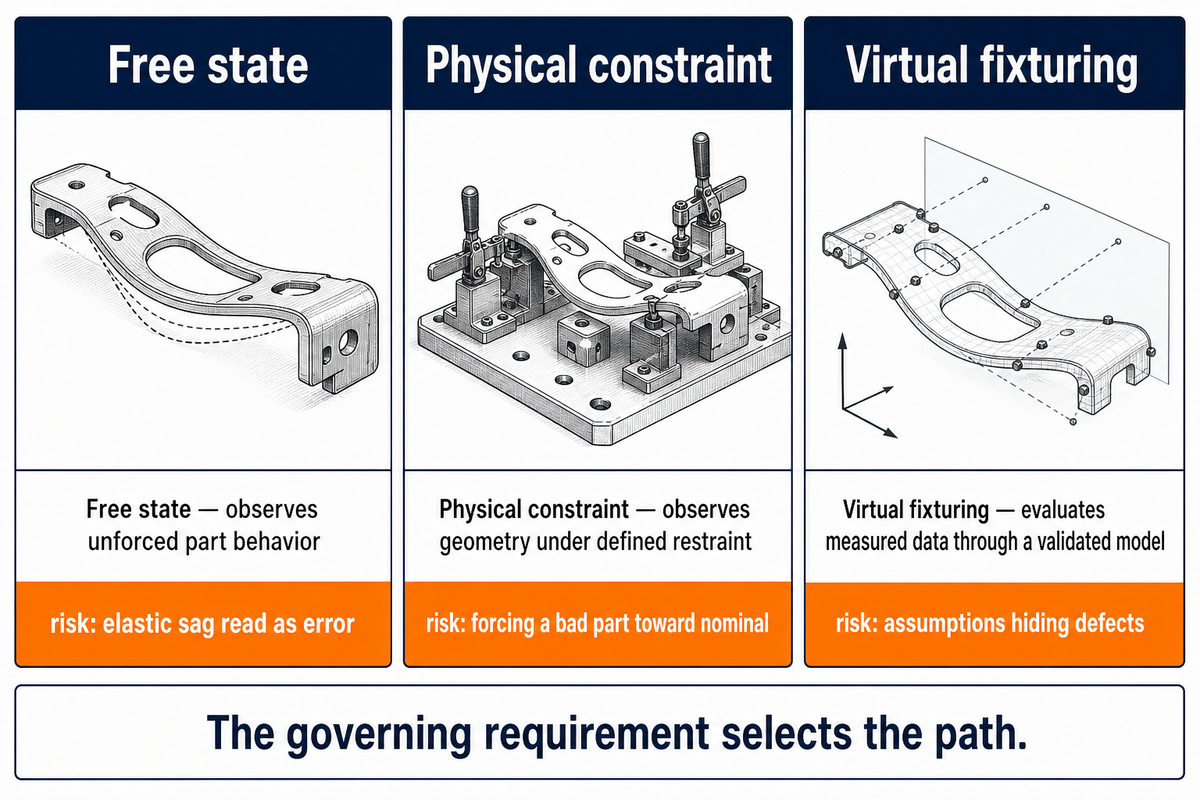
Required dimensions and features should be inspected in free state when the governing requirement calls for no external restraint. Use constrained inspection only when the drawing, specification, or approved functional method defines how the part is held. If the required design feature is not represented by either physical route, an approved and validated virtual-fixturing method may be used to evaluate the part.
| Question | Free state | Physical constraint | Virtual fixturing |
|---|---|---|---|
| What is observed? | Unforced part behavior under stated support and environment | Geometry under a defined restraint | Measured data evaluated through a validated deformation model |
| Primary authority | Drawing or default requirement | Drawing note or approved plan | Approved method plus validation evidence |
| Main risk | Mistaking elastic sag for manufacturing deviation | Forcing a bad part into compliance | Model assumptions hiding real defects |
The current ASME Y14.5 public listing identifies Y14.5-2018 (R2024) as the reaffirmed edition in effect. That page establishes the standard’s role in dimensioning and tolerancing, but this article does not reproduce protected clauses or drawings.
Answer in one lineThe valid state is the one authorized by the governing requirement and executed under controlled, reproducible conditions—not the state that returns the most favorable number.
What Free-State Inspection Actually Measures
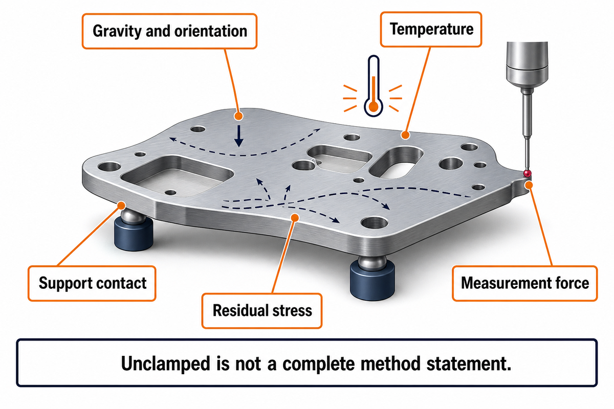
When free state is applied, the feature under consideration is interpreted without considering any forces that are intended to cause conformality of the part. Support, thermal expansion, residual stress, and measurement force remain part of the measurand; the method statement should define them rather than treat the part as floating without gravity or contact.
Gravity and orientation
A thin panel can show different sag when horizontal, vertical, or supported at different points.
A thin panel can show different sag when horizontal, vertical, or supported at different points.
Residual stress
Machining, forming, welding, or heat history can leave springback or distortion after the part is released.
Machining, forming, welding, or heat history can leave springback or distortion after the part is released.
Necessary support
Support prevents movement during measurement, but its location and contact area must not quietly become a shaping fixture.
Support prevents movement during measurement, but its location and contact area must not quietly become a shaping fixture.
Environment and probing
Temperature, stabilization, stylus force, optical setup, and surface condition can alter or bias the result.
Temperature, stabilization, stylus force, optical setup, and surface condition can alter or bias the result.
A 2019 peer-reviewed flexible-part inspection study describes free-state differences caused by gravity and residual stress. Therefore, “unclamped” is an inadequate method description, since the orientation of the part and its support state still affect the measurement condition rather than define part function.
Free-state record
Record orientation, support locations, contact materials, stabilization, measurement force or optical method, alignment, datum realization, and the time between release and measurement.
Record orientation, support locations, contact materials, stabilization, measurement force or optical method, alignment, datum realization, and the time between release and measurement.
Temperature is included in the definition. The official ISO 1:2022 catalogue page defines reference-temperature concepts for geometrical and dimensional properties and the measurand; the older ISO 1:2016 page is withdrawn.
When Constrained or Restrained Inspection Is Legitimate
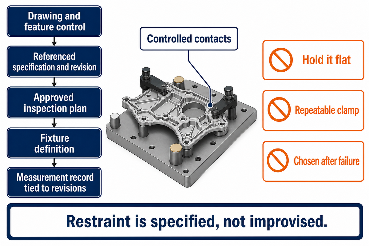
In this guide, a constrained result is treated as eligible for acceptance only when the controlling drawing, specification, contract, or approved inspection plan defines a restrained condition relevant to design intent. The method must state how the part is located and restrained, not merely label the result “constrained.”
Authority chain
- Drawing and feature control frame
- Referenced specification and revision
- Customer-approved inspection or quality plan
- Controlled work instruction and fixture definition
- Measurement record tied to those revisions
The current ASME Y14.5 listing identifies the applicable dimensioning-and-tolerancing standard; it does not define a part-specific restraint. For this guide’s decision framework, governing documentation must identify the external state and enough setup variables to reproduce it. Resemblance to final assembly is not adequate if the fixture adds unsupported contact, preload, or torque.
Legitimate evidence
- Named datum simulators and contact points
- Controlled load, torque, displacement, or fastener sequence
- Approved fixture drawing and revision
- Functional justification tied to the requirement
Not enough
- “Hold it flat” in an email
- A repeatable but undocumented clamp
- A torque chosen after a failed result
- A fixture made only to match nominal CAD
It’s the responsibility of qualified personnel in engineering and quality to resolve any gaps in the controlling documentation prior to commercial production. Blind acceptance due to the absence of controlling documents isn’t acceptable.
Terminology check before verification
In GD&T basics, a GD&T symbol, datum feature, geometric tolerance, or restrained condition note has meaning only within the applicable drawing and standard. Search language such as “free state inspection,” “GD&T free state,” and “restrained condition GD&T” points to the same document-control question. Searches for “fixture distortion inspection” or “inspect parts in free state” still require the same controlled method. Don’t assume that “unless otherwise specified” lets a shop override the default “free state” interpretation, or that all dimensions and tolerances apply in a free condition regardless of the controlling documents.
Phrases such as “restrained to datum,” “apply in a free state,” or “final assembly state” aren’t complete setup instructions by themselves. State whether the part is to be inspected in its free state, free and restrained under two requirements, or assessed through another approved path.
| Common wording | Clarify before inspection |
|---|---|
| Sheet metal parts, plastic parts, or rubber parts | Material behavior, orientation, springback, and how easily the feature can deform |
| Flatness checked with a gage or CMM | Support, datum realization, point strategy, and whether the restrained part is forced toward the desired shape |
| Fixture clamping force | Magnitude, direction, contact, sequence, displacement, and calibration evidence |
| Manufacturing process or assembly condition | Whether the goal is to inspect, assemble, assess function, or reproduce the final assembly state |
How Restraint and Support Create a False Pass, or a False Fail
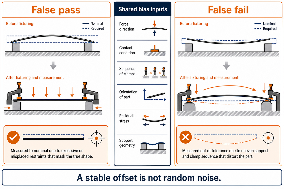
A part can be erroneously approved if a restraint forces it toward nominal. Conversely, a part can be erroneously rejected if a restraint bends an acceptable part away from its required state. Force magnitude is only one variable; direction, sequence, contact, orientation, residual stress, and workholding and support geometry can produce systematic bias.
| Mechanism | Possible distortion | Evidence to retain |
|---|---|---|
| Over-constraint | Part is forced onto too many locators | Contact map and locator sequence |
| Clamp load or torque | Local flattening, bowing, or twist | Load value, tool, calibration, sequence |
| Gravity and orientation | Sag changes between setups | Coordinate orientation and support diagram |
| Residual stress or springback | Shape changes after release or over time | Release timing and repeat observations |
| Soft contact or vacuum | Distributed pressure reshapes thin material | Contact material, area, and pressure |
One open-access 2023 experiment comparing optical scanning and CMM measurement on thin-wall Ti-6Al-4V parts reported a maximum discrepancy of about 8% under its tested conditions. The study is evidence that method choice and part flexibility can matter; it isn’t an 8% correction factor for other parts.
Repeatability trap
Ten similar readings prove that the setup repeats under those conditions. They do not prove that the setup represents the drawing requirement or that it is free from a stable fixture-induced bias.
Ten similar readings prove that the setup repeats under those conditions. They do not prove that the setup represents the drawing requirement or that it is free from a stable fixture-induced bias.
If the outcome of a measurement is affected by support, load, sequence or orientation, the difference must not be considered random. It is evidence that the inspection state needs to be defined and validated.
The State-of-Inspection Decision Ladder: Seven Checks
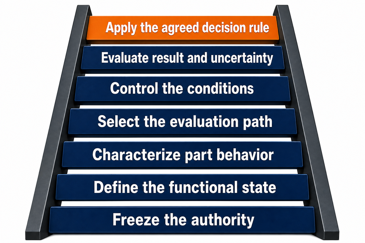
The State-of-Inspection Decision Ladder moves from authority to decision. Uncertainty and conformity should be addressed only after the inspection state is defined and validated. Reversing this sequence leads to the setup being chosen only after a determination has been made.
- 1. Freeze the authority. Record the drawing, specification, revision, feature, datum references, and any free-state modifier or restrained-condition note.
- 2. Define the functional state. Describe what the part experiences in service or assembly without assuming that every assembly force belongs in inspection.
- 3. Characterize part behavior. Check gravity, orientation, support sensitivity, residual stress, springback, material stiffness, and time-dependent change.
- 4. Select the evaluation path. Choose free state, authorized physical restraint, or validated virtual fixturing and document why it matches the authority.
- 5. Control the conditions. Fix supports, contacts, sequence, load or displacement, alignment, temperature, stabilization, equipment, and program.
- 6. Evaluate the result and uncertainty. Distinguish repeatability from systematic effects and confirm that traceability and the uncertainty chain are relevant to this measurand.
- 7. Apply the agreed decision rule. Keep the measured result distinct from the acceptance decision and record who owns false-accept and false-reject risk.
NIST explains that metrological traceability is a property of a specific result and doesn’t, by itself, guarantee fitness for purpose. The NIST guidance therefore supports an important boundary: calibrated equipment is necessary evidence, not proof that the chosen inspection state is valid.
NIST boundary
Metrological traceability does not by itself establish that a measurement is fit for a particular purpose.
Metrological traceability does not by itself establish that a measurement is fit for a particular purpose.
3-Path Inspection-State Framework for Flexible Parts
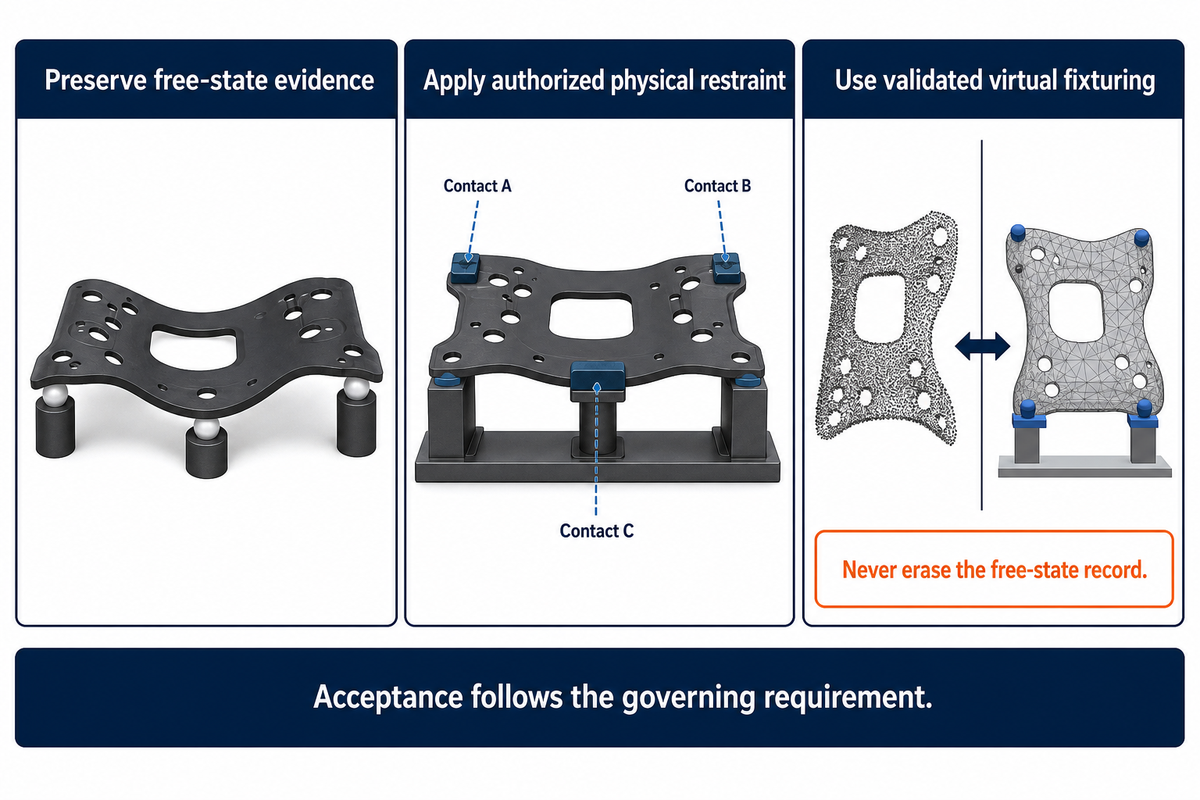
For this guide’s comparison workflow, preserve a free-state record before adding an authorized physical or validated virtual evaluation when that record is relevant to the feature. This keeps a fixture or model from erasing useful comparison information without claiming that free state always controls acceptance. The acceptance path still comes from the governing requirement, not from the sequence itself.
Path A: free-state record
Measure the unforced part under controlled orientation and support. Retain shape, alignment, conditions, and repeat observations.
Path B: physical restraint
Apply only the specified or approved fixture method. Record contacts, sequence, load, torque, displacement, and fixture revision.
Path C: virtual fixturing
Use a validated computational transformation with defined boundary conditions, material assumptions, residual-error checks, and approval.
A 2019 CIRP Annals paper proposes a fixtureless method that superposes gravity and fixturing-restraint effects before profile deviation is evaluated. This shows that physical clamping isn’t the only technical pathway, but the paper doesn’t turn every point-cloud transformation into an approved production method.
An earlier peer-reviewed ASME journal study evaluated a fixtureless method with simulated manufactured-part models. That is method-development evidence, not universal validation for every geometry, material, or production program.
Virtual-fixturing validation file
Retain the software and version, nominal CAD revision, material model, boundary conditions, assumed support or assembly points, gravity vector, validation part or simulation evidence, residual map, method uncertainty, and approval authority.
Retain the software and version, nominal CAD revision, material model, boundary conditions, assumed support or assembly points, gravity vector, validation part or simulation evidence, residual map, method uncertainty, and approval authority.
The three-path map supports analysis as well as decisions. A large difference between paths can reveal springback, local forcing, alignment sensitivity, or a model that is absorbing genuine manufacturing deviation.
What the Drawing and Inspection Plan Must Say
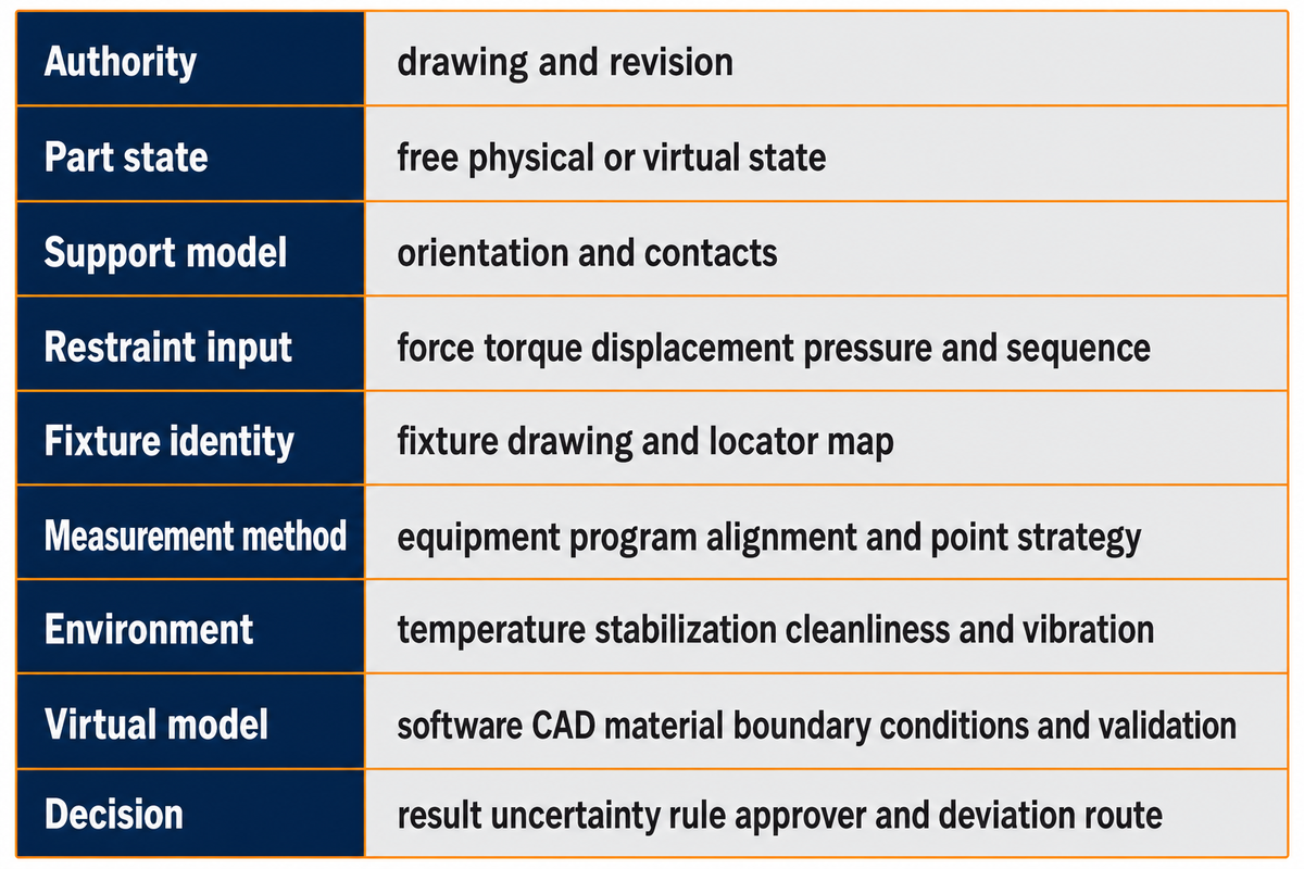
The controlled documents must make the inspection state reproducible. A reviewer should be able to identify the authority, rebuild the support or restraint, repeat the sequence, reconstruct the result, and see which decision rule converted that result into a disposition.
| Evidence category | Minimum fields | Why it matters |
|---|---|---|
| Authority | Drawing, revision, feature, tolerance, datum scheme, referenced standard | Stops requirement drift |
| Part state | Free, physically restrained, or virtually fixtured; release and measurement timing | Names the evaluated condition |
| Support model | Orientation, gravity vector, support coordinates, contact area and material | Exposes non-clamp deformation |
| Restraint input | Force in N, torque in N·m, displacement in mm, pressure in kPa, sequence and device | Quantifies shaping inputs |
| Fixture identity | Drawing, revision, locator map, fasteners and calibration status | Makes physical restraint reproducible |
| Measurement method | Equipment, program, probe or optical system, alignment, point strategy, filtering | Makes the result repeatable |
| Environment | Temperature in °C, stabilization in min, correction, cleanliness and vibration | Defines measurement conditions |
| Virtual model | Software, CAD revision, material assumptions, boundary conditions and validation | Makes computational effects reviewable |
| Decision | Result, uncertainty, decision rule, acceptance limits, approver, deviation route | Keeps data and disposition distinct |
For a drawing-specific review, send the revision, critical features, expected inspection state, and reporting requirements through Zhenling Metal’s metrology and inspection resource. The page is a project-review route, not independent proof of a part-specific uncertainty or acceptance result.
Do not leave this to the inspection report
The report should record an agreed method. It should not be the first document that reveals how a flexible part was constrained or which result was treated as authoritative.
The report should record an agreed method. It should not be the first document that reveals how a flexible part was constrained or which result was treated as authoritative.
Reading Conflicting Free-State and Constrained Results
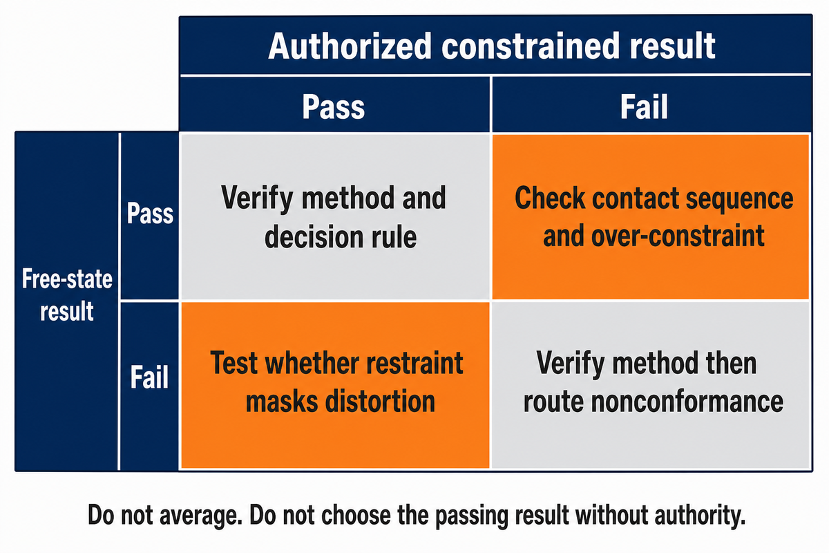
In the case of contradictory results, don’t take the mean. Don’t take the passing result unless justified. Verify the authority, both setups, systematic effects, uncertainty, and decision rule. Take the method permitted by the governing requirement.
| Free-state result | Authorized constrained result | Next defensible action |
|---|---|---|
| Pass | Pass | Release only after method and decision-rule checks are complete |
| Fail | Pass | Confirm which state governs and test whether the fixture is masking process distortion |
| Pass | Fail | Check restraint relevance, contact, sequence, over-constraint, and assembly simulation |
| Fail | Fail | Verify the method, then route through the controlled nonconformance process |
The result and the conformity decision are different artifacts. A NIST publication on decision rules and risk analysis explains that uncertainty evaluation is technical, while choosing the decision rule also involves cost and the balance between accepting a bad product and rejecting a good one.
Two records, not oneMeasurement record: what was measured, how, under which state, and with what uncertainty.
Decision record: which rule and authority turned that result into pass, fail, review, or concession.
Decision record: which rule and authority turned that result into pass, fail, review, or concession.
If a disagreement exposes an unclear drawing or plan, engineering clarification should precede final acceptance. A supplier-side fixture change cannot silently repair a requirement gap.
Situations That Do Not Justify Constrained Inspection
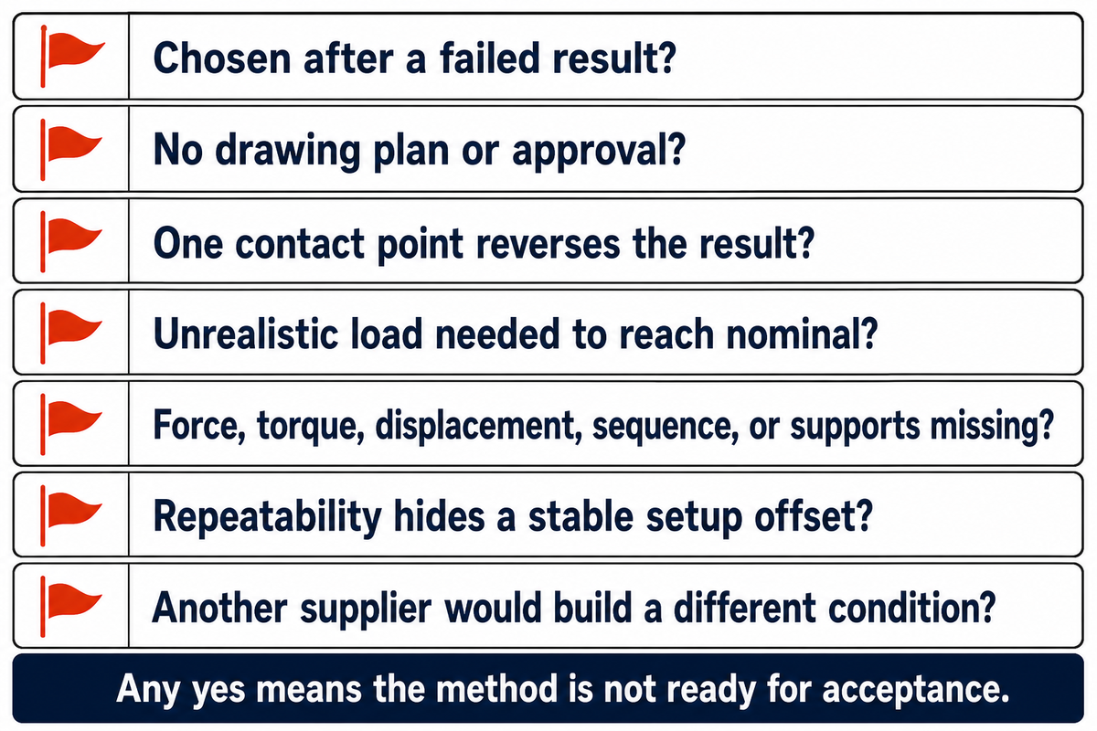
Constrained inspection is not justified merely because the part is flexible, the free-state result fails, or the fixture improves repeatability.
Invalid Restraint Test
- Was the fixture or force chosen after a failed result?
- Does the setup lack a drawing, plan, or approval reference?
- Can changing one contact point reverse the result?
- Does the restrained shape match nominal while requiring unrealistic load?
- Are torque, force, displacement, sequence, or support locations missing?
- Does repeatability hide a stable offset from the wrong setup?
- Would a different supplier reasonably build a different “constrained” condition from the same documents?
An affirmative answer to the Invalid Restraint Test does not automatically mean the part is nonconforming. A “yes” means the method is not yet ready to determine acceptance. The next step is to resolve the requirement or validate the method, not to adjust the clamp until the result changes; the NIST publication on conformity decision rules explains why the measurement result and the rule used to decide conformity must be treated separately.
Also invalid
Do not claim that virtual fixturing is objective simply because it is software-based. Boundary conditions, material assumptions, correspondence rules, filtering, and model validation can introduce their own systematic effects.
Do not claim that virtual fixturing is objective simply because it is software-based. Boundary conditions, material assumptions, correspondence rules, filtering, and model validation can introduce their own systematic effects.
Buyer Handoff Checklist Before Production
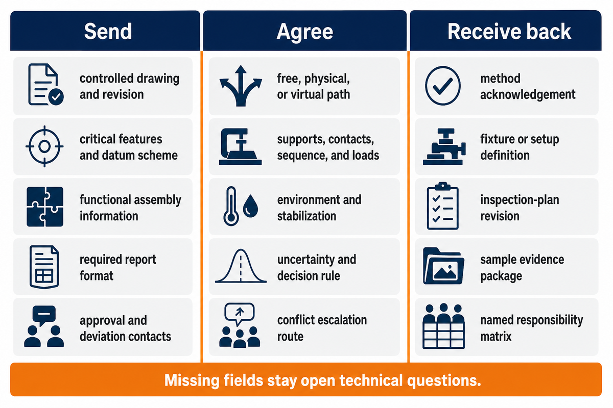
Prior to tooling and production, the buyer should transfer the required inspection state for the part or feature under consideration. The assignment should include the evidence to support the evaluation, the variables to control during the evaluation, and the type of evidence to be reported; any missing field should remain an open technical question, and no exemption should be assumed. Supplier discretion shouldn’t apply to an unevaluated or missing field.
| Send | Agree | Receive back |
|---|---|---|
| Controlled drawing and revision | Free, physical, or virtual path | Method acknowledgement |
| Critical features and datum scheme | Supports, contacts, sequence, loads | Fixture or setup definition |
| Functional assembly information | Environment and stabilization | Inspection-plan revision |
| Required report format | Uncertainty and decision rule | Sample evidence package |
| Approval and deviation contacts | Conflict escalation route | Named responsibility matrix |
Shanghai Zhenling Hardware Co., Ltd. manufactures non-standard machined components from customer drawings and samples. For a meaningful review, provide the part function and inspection-state requirements with the drawing rather than asking for a generic “CMM pass.” NIST metrological-traceability guidance treats traceability as a property of a specific measurement result, so the handoff should request the result, method, uncertainty, and traceability evidence together.
Define the state before the fixture is built
Share the controlled drawing, critical features, assembly condition, and required evidence package so the inspection method can be reviewed before production.
Frequently Asked Questions
What does free state mean in GD&T?
Free state means the specified requirement is evaluated without externally applied forces intended to shape the part, while gravity, necessary support, orientation, temperature, residual stress, and measurement interaction can still affect the result.
It does not eliminate gravity, necessary support, orientation, temperature, residual stress, or measurement interaction. The inspection record should state those conditions so another qualified reviewer can reproduce the result. If the drawing invokes a specific restrained condition, that controlled requirement can govern instead. A flexible part may also need a validated virtual-fixturing evaluation, but that method must be approved and must not hide real manufacturing deviation. Record the measurement result independently of the rule used to decide conformity.
What does the free-state symbol represent?
The free-state modifier identifies a geometrical requirement that applies with the part unrestrained, but it does not by itself define gravity, support, orientation, environment, measurement interaction, or the decision rule.
Its exact interpretation belongs to the applicable drawing and standards edition. Do not infer a complete support method, environment, or decision rule from the symbol alone. Those operating details still need to be controlled in the inspection plan and report. The same drawing can define another requirement for a restrained state, so the reviewer must connect each reported value to the correct feature control frame, state, and method revision.
When is constrained inspection required?
Constrained inspection is required when the governing documentation defines an authorized restrained condition for the feature being evaluated and identifies enough of the locating, support, load, or assembly state to make the method reproducible.
The documents should state enough about datums, supports, contacts, sequence, load, torque, displacement, or mating condition to reproduce the state. A shop preference or a fixture that makes the result pass is not sufficient authority. Resolve ambiguous requirements before final acceptance, and document the decision rule that converts the constrained measurement into a disposition.
What if a part fails in free state but passes when constrained?
Verify which state governs before assigning pass or fail.
Then confirm that the restraint matches the approved method and is not masking distortion. Preserve both results, the setup records, uncertainty, and the decision rule, and escalate an unclear drawing rather than choosing the favorable result.
How should fixture force be documented?
Document the value or controlled displacement, direction, application point, sequence, device, calibration status, and fixture revision so another qualified team can reproduce the restrained condition and verify that it matches the approved method.
Also record supports, contact materials, orientation, release timing, and any fastener torque because force alone does not define the state. Do not borrow a universal value from another geometry, material, or application.
Who decides which inspection result controls acceptance?
The authority named by the drawing, contract, specification, or approved quality plan decides which inspection result controls acceptance, while the measurement record remains separate from the rule and approval used to reach the disposition.
The laboratory or supplier reports the result, state, method, uncertainty, and any deviations; it should not create a new acceptance rule after seeing the data. Buyer and supplier should agree the decision rule and escalation owner before production.
Editorial boundary
The State-of-Inspection Map, Decision Ladder, Evidence Register, Conflict Disposition Matrix, Invalid Restraint Test, and Three-Path Method are editorial frameworks for this guide. They are not ASME, ISO, NIST, or Zhenling Metal acceptance rules.
The State-of-Inspection Map, Decision Ladder, Evidence Register, Conflict Disposition Matrix, Invalid Restraint Test, and Three-Path Method are editorial frameworks for this guide. They are not ASME, ISO, NIST, or Zhenling Metal acceptance rules.
References & Sources
- ASME Y14.5, Current Official Listing
- ISO 1:2022, Official Scope Record
- NIST, Metrological Traceability
- NIST, Conformity Decision Rules and Risk Analysis
- Materials, Thin-Wall Ti-6Al-4V Inspection Study
- ASME Journal, Inspection of Flexible Parts
- Precision Engineering, Semi-Geodesic Fixtureless Inspection
- CIRP Annals, Practical Conformance Evaluation of Flexible Parts
Sources accessed September 29, 2026.