ASME Y14.5 vs ISO 1101 is a comparison of different scopes: Y14.5 sets broad dimensioning rules, while ISO 1101 belongs to a larger GPS system. In both cases, go by the governing edition, and vet each of the affected requirements prior to converting a drawing.
Updated October 2026
- Matching symbols and numerical limits can still carry different geometric requirements.
- Size, form, datum construction and feature relationships require separate reviews.
- Comparison of historical examples illustrates the issue, and the invoked editions control the part.
- Conversion approval must address inspection evidence and the acceptance decision rule.
ASME Y14.5 vs ISO 1101 at a glance
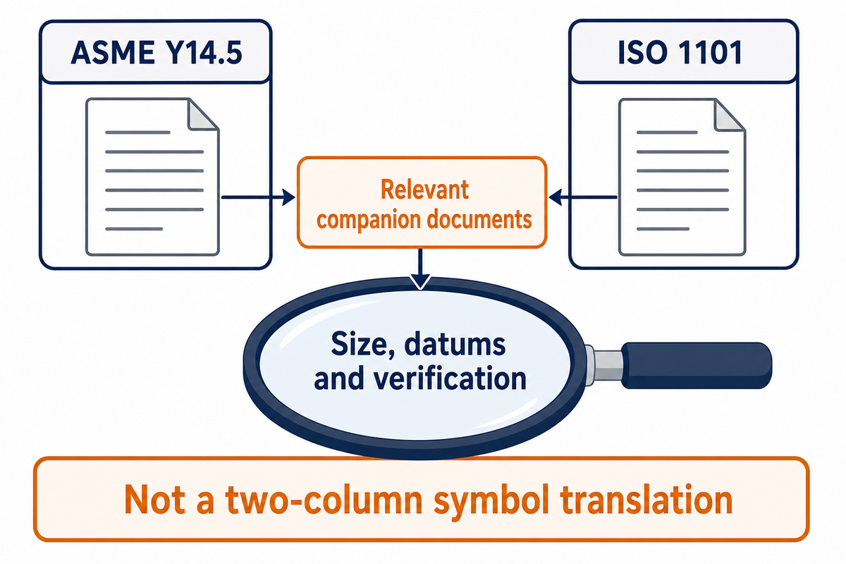
ASME Y14.5 covers symbols, definitions and defaults for dimensioning and tolerancing across drawings and digital models. ISO 1101 defines the geometrical specification language within ISO GPS. Comparing a complete drawing therefore requires the relevant companion documents, particularly those governing size, datums and verification, rather than a two-column symbol translation.
What is ISO 1101?
ISO 1101 is the International Organization for Standardization document for geometrical tolerancing of form, orientation, location and run-out. Its public scope describes the specification language and interpretation rules. Other geometrical product specifications cover related requirements. The standard number on a symbol chart cannot tell a supplier every rule governing the finished part.
The ISO 1101 public abstract and ASME Y14.5 description establish this scope difference. Use the table to identify which question belongs in which part of the drawing review.
Standard Scope Crosswalk
| Review question | Document scope to identify | Record in the drawing review | Limitations |
|---|---|---|---|
| Which geometric language? | Y14.5 or ISO 1101 within GPS | Governing system and edition | Organization names alone are insufficient |
| Which underlying defaults? | Y14.5 rules; ISO GPS fundamentals including ISO 8015 | Invoked principles and exceptions | A borrowed symbol does not import a complete system |
| What does size measure? | Applicable Y14.5 definitions; ISO 14405-1 linear sizes | Local or global size characteristic | Equal limits can describe different measurands |
| How is form related to size? | Applicable size/form rules and explicit controls | Required envelope or independent form limit | Size readings alone cannot settle every form requirement |
| How is the datum established? | Y14.5 datum rules; ISO 5459 | Feature, order and establishment rule | A fixture is not proof of correct datum construction |
| Which material requirement? | System-specific modifier rules; ISO 2692 where applicable | Feature requirement versus datum reference | Matching letters do not establish matching boundaries |
| Are features evaluated together? | Applicable pattern and combined-zone rules | Separate or related requirements | One shared numerical limit does not settle the relationship |
| How will the geometry be measured? | Measurement plan tied to the specified characteristic | Sampling, fitting and restraint conditions | Specification scope does not select every verification method |
| How will acceptance be decided? | Applicable decision rule; ISO 14253-1 or relevant ASME guidance | Uncertainty treatment and decision rule | Preserved geometry does not guarantee identical acceptance decisions |
The crosswalk is used to provide editorial guidance, and isn’t a required element. Public standard descriptions support its scope divisions; the released drawing still needs the applicable normative requirements. Keep the basic symbol learning in the GD&T Symbol Reference and return to the feature being cited.
If both suppliers can present GD&T the same way, the ambiguity isn’t resolved and a purchasing objection is valid. Before comparing, ask each supplier to identify the same drawing revision and standard edition.
Declare the governing GD&T standard and edition
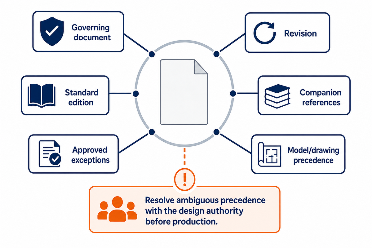
In cases where neither the controlled product definition nor its requirements clear up a conflict, supplier location, millimetre units and software defaults aren’t the final say. Record the edition, relevant companion references and any approved departures, then resolve ambiguous precedence with the design authority before production.
Consider a hypothetical order for a 20 mm shaft. The drawing invokes an ASME standard, while a supplier’s inspection template selects ISO by default because the dimensions are metric. The buyer then sends an old model with a different revision. Neither the 20 mm nominal size nor the supplier’s country resolves which file governs. Procurement should hold the conflicting interpretation, engineering should identify the controlling revision, and quality should check the evaluation settings against that decision. Once the files agree, the supplier can quote the specified work. This example contains no measured defect rate or claimed saving; it shows why unit choice and drawing authority need separate fields.
Use a short declaration record: governing document, revision, standard edition, companion references, approved exceptions, and model/drawing precedence. Detailed drawing tolerance interpretation belongs alongside this record. General limits in the general-tolerance title-block notes require their own scope check.
A supplier can price a stated exception. It can’t price two conflicting definitions reliably. Don’t remove an existing reference merely to make the title block look consistent.
Size and form: Rule 1 versus independency
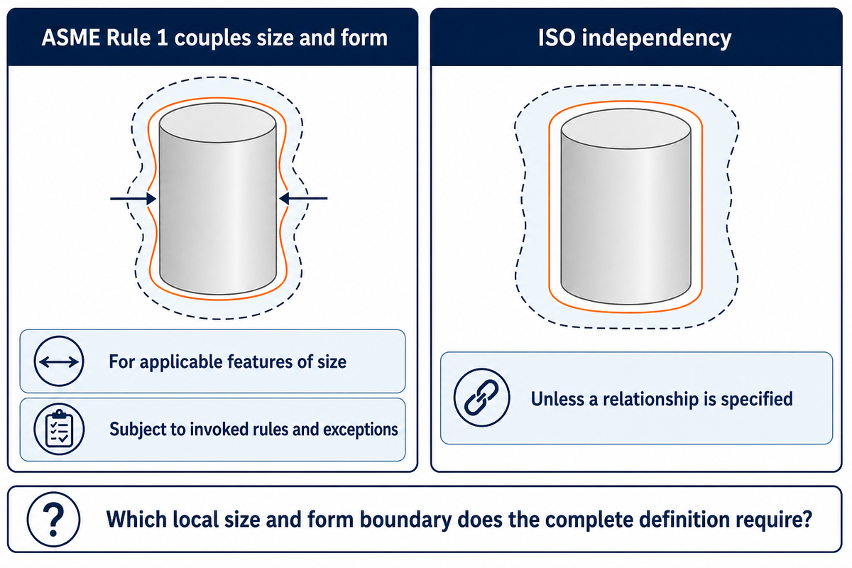
ASME Rule 1 couples size and form for applicable features of size, subject to the invoked rules and exceptions. ISO independency treats requirements independently unless a relationship is specified. Identical diameter limits therefore require a second question: which local size and form boundary does the complete definition require?
The ASME teaching outline makes the broad distinction explicit. For a regular external feature of size, maximum material condition (MMC) defines the largest size allowed and least material condition (LMC) the smallest size allowed. Those labels don’t replace the full form requirement.
Take a hypothetical cylindrical shaft with limits of 19.90 mm and 20.00 mm. Its size interval is 20.00 mm minus 19.90 mm, or 0.10 mm. Suppose a reported local reading is 19.95 mm. That number lies between the stated limits, yet a bent shaft with that reading can still fail the required full-length form boundary. Engineering must identify the specified size characteristic and any form control; quality must then select evidence that addresses both. A bent shaft cannot be declared acceptable under ISO merely because one reading is 19.95 mm. Equally, subtracting that reading from 20.00 mm does not by itself establish the complete permitted geometry.
Zbigniew Humienny’s 2021 comparative paper, Figures 1–2, uses a different published example: 20 mm maximum and 19.8 mm minimum. It distinguishes a global envelope from a local size defined by a sphere. The paper explains why adding an envelope requirement while retaining a different local-size definition isn’t fully equivalent.
That is a historical illustration under the editions examined in 2021. ISO 14405-1 has since reached its 2025 edition. This example does not authorize copying its modifiers to a new released drawing.
For a 19.90-20.00 mm shaft, the 0.10 mm interval is just a size interval. If a quotation assumes that it also settles straightness, the supplier has to state the supporting rule or separate control, and only then can it be accepted.
Datum features and material-condition modifiers
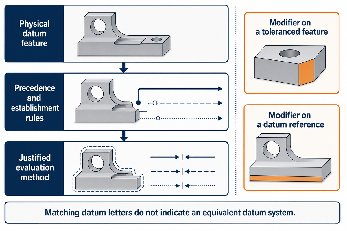
Matching datum letters don’t indicate an equivalent datum system. A conversion review has to identify the physical datum feature, its precedence and the applicable establishment rules. A modifier attached to a toleranced feature has a different answer from a modifier attached to a datum reference.
The ISO 5459:2024 abstract defines datum specification terminology and methodology, but excludes the verification operator from its subject. It directs detailed maximum and least material requirements for datums to ISO 2692. A standard reference therefore cannot substitute for a justified physical or mathematical evaluation method.
See the complete set of datum features. Review primary, secondary and tertiary precedence, datum targets, datum feature patterns and the remaining degrees of freedom. A datum reference frame establishes the reference for specified controls; fixturing must realize the intended relationship without introducing an unjustified constraint. Detailed CMM datum setup errors deserve a separate troubleshooting check.
Do
- Identify the physical feature behind each datum reference.
- Check establishment rules under the invoked edition.
- Explain how the evaluation realizes the reference.
Don’t
- Approve a setup solely because its letters match.
- Read every material modifier as the same instruction.
- Assume a fixture photograph proves the datum construction.
If a supplier says the existing setup is unchanged, ask for the reasoning at the feature level. Reusing hardware can be sensible; reusing an unexamined interpretation leaves the comparison unfinished.
Position and profile tolerance: look past the symbols
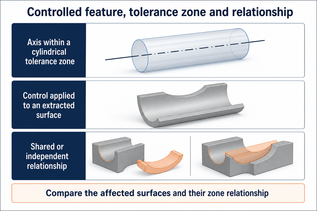
Position tolerance and profile tolerance must be evaluated with respect to the controlled feature, tolerance zone and relationship to other features. A familiar feature control frame does not prove equivalent meaning across systems. Compare what geometry is constrained, how the zone is located and whether several requirements apply separately or together.
In Humienny’s 2021 comparison, ISO position tolerancing can locate a nominally flat surface, whereas ASME position has a different feature scope. An ASME position callout associated with an axis or center cannot simply be copied onto every surface. A requirement relative to a datum reference also needs the correct reference construction.
For example, a condition requiring an axis to remain within a cylindrical tolerance zone differs from a control applied to an extracted surface. Profile of a line and profile of a surface on the other hand describe different extents of control. Consider the profile controls before comparing the figures.
Figures 7-8 of the same paper illustrate coplanar surfaces with a 0.06 mm requirement. The surfaces can be in a shared or independent relationship. Two separate 0.06 mm zones do not become one combined 0.06 mm zone merely because their widths match. The ISO notation illustrated in the paper is pertaining to the paper’s edition.
Common failure modes in a frame-only conversion
A frame-only conversion removes controlled geometry, and in the process, a symbol may be retained. An example illustrates the shared relationship of surfaces isn’t the same as evaluating surfaces independently. Compare the affected surfaces and their zone relationship before deciding whether the numerical limit can remain.
Another failure is treating a local size reading as complete evidence for an envelope. The paper’s 20 mm and 19.8 mm example separates those requirements. A report that names only “diameter” can hide the size characteristic used by the software. Require the report to identify what was evaluated rather than accepting an unexplained green result.
A third failure happens when a historical conversion is performed to a different edition without review. The 2025 linear-size catalog shows an update, but its abstract doesn’t prove all older instances are the same. If the supplier cannot resolve a feature’s interpretation, engineering should decide the requirement before quality approves the evaluation. Purchasing should evaluate the cost of the agreed-upon scope not an apparent saving based on differences in geometry.
Convert a drawing through controlled review
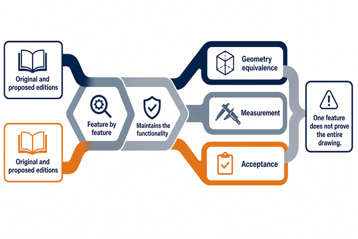
A “controlled conversion” compares the requirements feature by feature, recording why the proposed definition maintains the functionality. Keep the original and proposed editions visible. Then, separate evidence of geometry equivalence, measurement, and acceptance. A comparison of one feature doesn’t prove equivalence of the entire drawing.
Humienny examined twelve selected examples, demonstrating that useful conversions are possible with suitable changes. The result is bounded. The following filled record is an editorial method for ISO GPS and ASME reviews, not a standard-mandated form or an approved drawing.
Conversion Impact Register
| Review field | Example entry | Owner and required evidence | Limitation / disposition |
|---|---|---|---|
| Feature identity | Shaft diameter, 19.90–20.00 mm | Engineering: matching feature identifiers in both revisions | Scope identified; no acceptance decision |
| Existing rule | ASME Y14.5-2018 invoked in this hypothetical original | Engineering: complete original notes and exceptions | Do not infer rules from the nominal 20 mm size |
| Proposed rule | ISO GPS; relevant editions to be approved, including linear sizes | Engineering: proposed standard list | Hold until editions are fixed |
| Size interval | 20.00 mm − 19.90 mm = 0.10 mm | Engineering: intended local/global size characteristic | Arithmetic checked; measurand unresolved |
| Form boundary | Required full-length boundary to be identified | Engineering: functional requirement and rule comparison | A 19.95 mm reading alone is insufficient |
| Datum relationship | Review each affected reference and modifier | Quality: datum construction matched to the definition | Matching letters are insufficient |
| Measurement plan | Identify sampling, fitting and restraint or free state | Quality: justified method and evaluation settings | Do not infer form from sparse size readings |
| Acceptance rule | State uncertainty treatment and governing/agreed decision rule | Quality and customer: feature-specific decision basis | Equal geometry need not produce equal borderline decisions |
| Release decision | Hold this example pending unresolved technical entries | Engineering approves intent; procurement uses the approved scope | No production release from this illustrative register |
Quality can connect the record to the appropriate GD&T inspection methods. Engineering defines the functional requirements; the plant manager requires a manufacturable definition; procurement requires comparable scope. Tolerance analysis should rely on that definition, rather than assuming two standards would provide the same inputs.
For the example shaft, the difference between 19.90 mm and 20.00 mm remains 0.10 mm under either unit calculation. The unresolved issue is what those limits measure. That is the point at which an ASME vs ISO review needs engineering judgment, not another subtraction.
Align supplier quotations and inspection evidence

Comparable supplier quotations only exist if they’re based on the same functionally defined requirements and inspection evidence. When invited to provide a quotation, suppliers should be required to explain how they’ll interpret a critical design feature tied to the invoked rules, and how they’ll evaluate and accept that feature. A software name or training certificate cannot establish how that particular feature will be interpreted.
Take a copy of this short record for each quotation: supplier, controlling revision, model/drawing precedence, critical feature, measured characteristic, inspection evidence, acceptance rule, quoted deviations and their costs. Compare like for like, and only then, decide if a lower quotation price reflects the same work.
“Size controls form, too”
Suppose two suppliers evaluate the hypothetical shaft near its 20.00 mm upper limit. Both report 19.99 mm, but their uncertainty estimates and acceptance rules are not supplied. Different uncertainty treatment or decision rules can turn the same 19.99 mm reading into different acceptance decisions. Quality should verify the measurement basis and the acceptance rule before comparing results. An assumed 0.01 mm numerical margin is not a universal allowance for uncertainty. Engineering should also verify that the reported dimensions are for the same size characteristic and the same drawing revision. The purchasing task is then specific: price the agreed evidence and resolve any difference in scope. No acceptance rate or financial return can be determined from the given information.
ISO 14253-1:2017 covers uncertainty-aware conformity decisions, including measurements near limits. ASME B89.7.3.1 provides related decision-rule guidance. Keep detailed measurement uncertainty near a tolerance limit separate from the nominal geometry comparison.
For wider requirements, use the CNC machining service scope when writing an enquiry. Send the controlling files and identify unresolved standard interpretations with them.
Standards updates: revalidate before changing editions
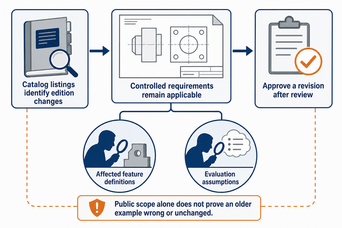
Changes to catalog listings identify edition changes, but don’t re-write a drawing released at an earlier date. Review the affected feature definitions and evaluation assumptions before approving a revision, especially when earlier technical examples used different companion editions. This is especially important when the companion editions of the standards being cited differ from earlier examples.
What is the latest version of the GD&T standard?
ASME and ISO each set their own latest edition. In October 2026, the checked catalogs list ASME Y14.5-2018, reaffirmed in 2024, and ISO 1101:2017, confirmed in 2022. Relevant companions include ISO 5459:2024 and ISO 14405-1:2025. The applicable version remains the one established by the controlled requirements.
| Document | Checked status | Review consequence |
|---|---|---|
| Y14.5 | 2018 (R2024) | Reaffirmation is not a newly numbered 2024 technical edition |
| ISO 1101 | 2017; confirmed 2022 | Keep the geometrical language edition explicit |
| ISO 5459 | 2024; previous 2011 withdrawn | Review datum requirements when changing editions |
| ISO 14405-1 | 2025; previous 2016 withdrawn | Recheck historical linear-size examples before adopting them |
The ISO 14405-1:2025 catalog confirms publication in August 2025 and describes default and special linear-size operators. Its abstract does not identify every technical difference from 2016. Recheck older linear-size examples against the 2025 edition before adopting them.
ASME Y14.5-2009 remains visible in older training and drawings. A supplier citing it has not necessarily made an error; first check what the order invokes. The Y14.5 standard, ASME GD&T teaching and ISO GD&T standards must be read with their editions. These are technical reference checks, not evidence of market adoption rates.
Key takeaway
Keep one controlled interpretation for each feature: governing edition, geometric requirement, measurement evidence and acceptance rule. A copied symbol or unchanged tolerance value cannot establish all four.
Frequently asked questions
What is the difference between ASME and ISO standards?
ASME and ISO standards differ in default rules: ASME Rule 1 couples size and form for applicable features of size; ISO treats them independently unless specified.
Both organizations publish many documents, so compare the requirements actually invoked. For geometric dimensioning and tolerancing, Y14.5 contains broad rules and defaults, while ISO 1101 belongs to a larger GPS system. A useful ISO vs ASME comparison also identifies relevant size, datum and verification documents. Matching symbols alone cannot establish that two definitions impose the same requirement.
What does ASME Y14.5 mean?
ASME Y14.5 is the American Society of Mechanical Engineers standard for dimensioning and tolerancing.
Its scope includes symbols, definitions and interpretation requirements for drawings and digital product models. The standard reference should be read with the applicable edition and approved exceptions. Knowing the number alone does not resolve a conflict between a drawing, a supplied model and purchase requirements. Those documents need an agreed controlling interpretation before a supplier prepares its inspection program.
Can ISO GPS position apply to a specific surface only?
Yes, in Humienny’s 2021 comparison ISO position locates a nominally flat surface; ASME position has a different feature scope.
Do not decide from the symbol alone. The toleranced feature, indicator placement, specification elements and applicable edition determine what is controlled. A surface-related requirement cannot simply be read as an ASME axis control. Ask engineering to identify the intended feature before programming inspection. The cited 2021 comparison explains this distinction; it is not a complete current-edition conversion instruction.
What does GD&T stand for?
GD&T stands for geometric dimensioning and tolerancing.
Engineers use GD&T to communicate allowable geometric variation. The symbols require interpretation under the invoked rules. Familiarity with geometric tolerancing does not remove the need to check the complete feature definition and governing edition.
Can I invoke ISO 8015 and ASME Y14.5 on the same drawing?
Yes, but only with an explicit, approved treatment of potentially conflicting rules.
Do not add both as a shortcut to compatibility. Different dimensioning and tolerancing principles can leave suppliers with competing assumptions. If a customer deliberately combines provisions, obtain an approved interpretation identifying affected features, editions and precedence. Record the decision in the controlled package before quotation or inspection. Removing an existing reference also needs engineering review; it is not merely title-block cleanup. A specific ISO standard reference cannot resolve every conflict with the rest of the drawing.
Does a GD&T certificate prove that a supplier interpreted my drawing correctly?
No. A certificate covers personal knowledge; a particular feature’s interpretation needs feature-specific evidence.
Request the feature-specific explanation, inspection method and resulting evidence. Keep each tied to the controlling revision and standard edition. Personal knowledge certification and evidence about an individual part answer different questions.
Can I reuse a CMM program after converting a drawing to another standard?
Reuse needs a review of the requirements and evaluation assumptions affected by the conversion.
Check the controlled feature, datum construction, material-condition treatment, geometric tolerances, point strategy and result calculation. An unchanged numerical limit does not prove the program remains appropriate. Keep old and new revisions identifiable, document the review and validate affected results before acceptance. Include measurement uncertainty and the applicable decision rule where relevant. When the intended function cannot be preserved by direct conversion, return the decision to engineering rather than adjusting the program to produce a passing result.
References & Sources
Why Zhenling separates these drawing rules
Zhenling Metal publishes this comparison to support clearer drawing-led CNC enquiries. The standard scopes and edition dates come from public original sources; the conversion examples are either attributed historical research or explicitly hypothetical. The crosswalk and register organize engineering questions rather than certify a part or replace the invoked standard. No customer measurements or company qualifications are implied.