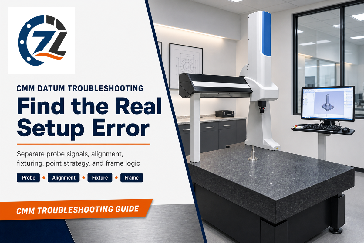
CMM datum setup errors are hardware-signal, alignment, fixturing, probing, part-condition, or software problems that prevent a trustworthy datum-based measurement. A controller or probe-head “Datum Error” can be a device- or product-specific signal. Measurements, on the other hand, can be affected by the CMM datum reference frame, fixture, point strategy, part condition, machine state, environment, context, or software alignment. Always consider both initial tracks because the effects can coexist.
Track 1: machine signalA controller LED, head-indexing failure, collision, or product-specific message starts with a safe stop and the OEM troubleshooting route.
Track 2: measurement resultA routine that completes but shifts, disagrees, or changes after re-fixturing starts with the drawing, alignment, fixture, probe, points, and program.
Always maintain a record of the state of the system. That includes the software revision, alignment results, raw measurements, state of the fixture, configuration of the stylus, state of the environment, and the temperature history. It’s always better to document the state of the system when a defect occurs rather than replace it with an unknown state.
Scope boundary
This guide is a vendor-neutral troubleshooting sequence. It does not set a universal point count, clamp force, thermal band, acceptance threshold, or calibration interval, and it does not claim a particular CMM model or laboratory accreditation for Shanghai Zhenling Hardware.
This guide is a vendor-neutral troubleshooting sequence. It does not set a universal point count, clamp force, thermal band, acceptance threshold, or calibration interval, and it does not claim a particular CMM model or laboratory accreditation for Shanghai Zhenling Hardware.
1. First Identify Which “Datum Error” You Have
In CMM troubleshooting, the signal location and event order should dictate the next check. For example, a controller condition and a questionable coordinate from a completed alignment prompt different CMM checks. However, the alignment process may itself introduce errors, and a probing-system fault can also influence the same result. Therefore, all evidence should be carefully documented.
2-Track Initial Triage Framework
| Observable condition | First track | Preserve | Next owner |
|---|---|---|---|
| Controller LED or head-indexing Datum Error | Hardware/OEM | Exact message, position, stylus, event sequence | Machine or probe-head service |
| Alignment completes but result shifts | Metrology setup | Program, fit, fixture, raw points | Metrology owner |
| Change appears after re-fixturing | Physical/coupled effect | Contact map, clamp sequence, probe state | Fixture and process owners |
Renishaw’s example of a ‘Datum Error’ is found in their official PH10 knowledge-base to describe a named non-repeatable locking condition and is product specific. This example of a Datum Error definition is valid only for the product family described and doesn’t constitute a general definition for the broader class of CMM error conditions.
Do not collapse the tracks
A cable or head fault can alter probing, while a fixture or program problem can appear without a hardware alarm. Triage selects the first safe check; it does not prove root cause.
A cable or head fault can alter probing, while a fixture or program problem can appear without a hardware alarm. Triage selects the first safe check; it does not prove root cause.
2. Rebuild the Datum Chain From the Drawing

Trace the setup as four different things: the physical datum feature on the part, the contact or simulator that interacts with it, the derived datum established from that interaction, and the datum reference frame used for coordinates. Treating these as synonyms is a common way to align to the wrong surface.
1. Datum feature
The real feature identified on the controlled drawing.
The real feature identified on the controlled drawing.
→
2. Contact or simulator
The physical or mathematical interaction used by the plan.
The physical or mathematical interaction used by the plan.
→
3. Derived datum
The ideal reference established from the feature.
The ideal reference established from the feature.
→
4. Reference frame
The ordered axes and origin used to evaluate requirements.
The ordered axes and origin used to evaluate requirements.
The ISO 5459:2024 official record covers datums and datum systems in geometrical product specifications. Use the governing drawing and specification rather than copying a generic alignment from another part, and record any modifier, precedence rule, basic dimension, or interpretation decision that changes construction. The datum feature symbol identifies the referenced feature on the drawing; it does not automatically make the machine table a datum simulator.
Do you probe the feature or the simulator?
A CMM commonly samples the physical datum feature and mathematically constructs the derived datum. A physical simulator can be appropriate in a functional-gaging or fixture strategy, but the drawing, feature, governing specification, and approved inspection plan decide the route; the machine table is not an automatic substitute for datum A.
A CMM commonly samples the physical datum feature and mathematically constructs the derived datum. A physical simulator can be appropriate in a functional-gaging or fixture strategy, but the drawing, feature, governing specification, and approved inspection plan decide the route; the machine table is not an automatic substitute for datum A.
3. Check the Degrees of Freedom Before Adding More Points

A 3-2-1 alignment indicates what datums govern translational and/or rotational degrees of freedom and what motion (if any) is left unconstrained.
| Datum step | Constructed feature | Intended constraint | Observed issue | Next test |
|---|---|---|---|---|
| Primary | Plane, axis, or other specified feature | Record named motions | Rocking, tilt, weak construction | Review contacts and spatial coverage |
| Secondary | Specified second feature | Record remaining motions | Conflict or redundancy | Check precedence and feature direction |
| Tertiary | Specified final feature | Complete remaining constraint | Residual translation/rotation | Check origin, modifier, and sequence |
Adding extra points can be justified if they’re sampled to represent a stable feature and can aid in defending a construction. Extra points can’t correct an erroneous datum, feature type, precedence, or constraint; a dense cluster can still repeat the same local high or low area.
Useful review questionIf the point count doubled but every point stayed in the same small patch, would the constructed feature become more representative? If not, change the spatial strategy before changing the count.
4. Check Support, Location, Clamping, and Probe Interaction

With the degrees of freedom mapped, determine the function of each contact. Contact may be defined by support or by a locator. The clamp maintains contact; however, tightening the part doesn’t prove that it is stable or undistorted.
Locate
Identify where position is established and whether chips, burrs, wear, or damaged contacts shift it.
Identify where position is established and whether chips, burrs, wear, or damaged contacts shift it.
Support
Find rocking, unsupported spans, compliance, orientation effects, and contacts that engage inconsistently.
Find rocking, unsupported spans, compliance, orientation effects, and contacts that engage inconsistently.
Clamp
Record sequence and controlled force method where one exists; watch for over-constraint and deformation.
Record sequence and controlled force method where one exists; watch for over-constraint and deformation.
Probe
Review tip geometry, approach, location, force behavior, head position, and interaction with part compliance.
Review tip geometry, approach, location, force behavior, head position, and interaction with part compliance.
The fixture, probe, part, machine, software, environment, and thermal state comprise a coupled measurement system. The applicable method defines any thermal band or clamp force for the coupled system, rather than this article. Check cleanliness, contact marks, orientation, gradients, and vibration where they are relevant to the task. Stabilization history and vibration may be reported, if it may impact the evaluation of the system. When using a CMM for part setup, stabilize the real part in the inspection room, record humidity around the part being measured, map contact points, and qualify the probe; these controls protect precision, keep CMM measurements reliable, and do not hinder troubleshooting.
Controlled reseat
Photograph or map the original contacts, remove and reseat the same part under the same documented sequence, then compare the result vector. Review CNC workholding for broader fixture context, while keeping the inspection alignment decision inside the metrology plan.
Photograph or map the original contacts, remove and reseat the same part under the same documented sequence, then compare the result vector. Review CNC workholding for broader fixture context, while keeping the inspection alignment decision inside the metrology plan.
5. Test the Probe and Point Strategy

After documenting fixture contacts, compare the current probe and point map with a known-good qualification state and the actual geometry used to construct the datum. Document probe and stylus IDs, head positions, approach vectors, rejected points, surface condition, and point coordinates before changing anything. Capture point coordinates. Do not adjust the qualification state or revise the approach routine until the original probe evidence is saved.
| Check | Why it matters | Evidence to save |
|---|---|---|
| Qualification and stylus state | A stale or mismatched state can affect corrected contact coordinates | IDs, time, sphere, head positions, status |
| Approach and clearance | Direction and access can create deflection, collision risk, or unintended contact | Vectors, speeds, clearance moves |
| Point distribution | Local clusters can bias a fitted plane or axis | Coordinates, map, rejected points |
| Fit and feature definition | The same points can support different mathematical constructions | Feature type, fit, filters, settings |
Programming errors can affect a CMM result without proving that machine calibration is out of adjustment. Feature definition, point rejection, probe position, fit, and CMM programming can all affect a measurement result. Double-check measurement routines when a CMM setup evaluates parallelism, perpendicularity, position tolerance, or a projected tolerance zone. Skew in the reference surface, an incorrect tolerance, or a routine that fails to constrain the intended motion can simulate significant errors.
Point-count boundary
There is no universal number beyond the geometric minimum. Size, form, risk, coverage, construction, fit method, and the governing procedure determine whether more points add useful information.
There is no universal number beyond the geometric minimum. Size, form, risk, coverage, construction, fit method, and the governing procedure determine whether more points add useful information.
6. Separate Part Form From Datum Construction
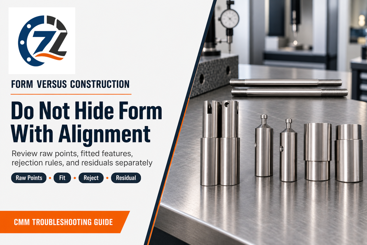
Anomalous features can result from a combination of raw-point irregularities, residues, surface conditions, part form, or a datum formed in an unusual or unexpected position; inspect the raw coordinates before moving the system.
Evidence of real form
- Structured raw deviations across the feature
- Repeatable local highs, lows, lobing, or interruption effects
- Changes linked to spatial sampling or surface condition
Evidence of construction sensitivity
- Result changes with fit or feature definition
- Different point maps move the derived axis or plane
- Datum order or modifier changes the reference frame
Coordinates and features should not be shifted merely to make a best-fit or datum evaluation appear closer to the intended relationship. If conflicting information exists in the drawing, evidence may be frozen and the drawing owner consulted.
Red lineAn unexplained coordinate adjustment changes the measurement model. It is not a corrective action until the controlled drawing, governing specification, and authorized reviewer support it.
7. Trace Coordinate and Software Mismatches

Routines can be executed without verifying the correctness of CAD revisions, nominal vectors, datum orders, modifiers, feature definitions, and alignment. When routines fail, compare them to a known good, controlled version instead of relying on memory.
Alignment diff checklist
- Drawing and CAD revision
- Units and scale
- CAD origin versus drawing datum system
- Positive axis directions
- Selected features and nominal vectors
- Datum order and modifiers
- Feature fit and filtering
- Manual/pre-alignment transition
- Program and software revision
- Changed defaults or saved settings
PC-DMIS, Calypso, and Hexagon may differ in command names and functions. Define command functions in vendor manuals and state the command settings. Zeiss, Mitutoyo, and other platform documentation help teams interpret commands. One pitfall is assuming labels transfer between systems; hands-on review, regular calibration, and ongoing education can prevent that avoidable misunderstanding when using a datum simulator.
Coordinate-frame context
The broader CNC coordinate system concept can help cross-functional teams discuss origins and axes. The inspection program still needs its own drawing-controlled datum reference frame and alignment evidence.
The broader CNC coordinate system concept can help cross-functional teams discuss origins and axes. The inspection program still needs its own drawing-controlled datum reference frame and alignment evidence.
8. Use Controlled Repeats to Narrow the Next Check

After software settings are verified, the “Repeatability Triangle” is an editorial screen for process variation; it narrows the next investigation but does not prove root cause, accuracy, or conformity.
1. Repeat without disturbance
Same part, program, stylus, setup, and recorded conditions
Same part, program, stylus, setup, and recorded conditions
2. Re-fixture the same part
Record contact, support, clamp sequence, and orientation
Record contact, support, clamp sequence, and orientation
3. Test another representative part
Only after the first two comparisons are understood
Only after the first two comparisons are understood
If process variation occurs materially in an undisturbed repeat under the applicable decision rule, investigate software state, probe behavior, environment, and machine behavior; do not infer a specification failure or datum-order problem from repeatability alone. If the undisturbed repeat is stable but a same-part re-fixture moves, investigate probe interaction and coupled support, including clamping sequence, fixture contact, and relative orientation. If process variation occurs materially among representative parts after both same-part checks remain stable, evaluate variation in the process and the parts sampled before changing the datum setup.
Repeatability is not accuracy
A stable sequence can retain systematic CMM, probing, compensation, thermal, software, or interpretation error. Compare any “material” change with the applicable tolerance, task-specific uncertainty, control plan, and responsible engineer’s decision rule, never a universal threshold invented for this article.
A stable sequence can retain systematic CMM, probing, compensation, thermal, software, or interpretation error. Compare any “material” change with the applicable tolerance, task-specific uncertainty, control plan, and responsible engineer’s decision rule, never a universal threshold invented for this article.
One University of Michigan application study offers a bounded illustration: pooled repeatability for the compared alignment methods was around 0.08 mm to 0.10 mm, while average mean differences were around 0.54 mm to 0.56 mm. Those numbers belong to that study, not to your tolerance; their value is showing that similar repeatability doesn’t guarantee agreement.
Write down the invariants
For every repeat, label the program, stylus, head position, environmental record, thermal history, disturbance status, part identity, fixture sequence, and result vector. Without that record, “we ran it again” is not a controlled comparison.
For every repeat, label the program, stylus, head position, environmental record, thermal history, disturbance status, part identity, fixture sequence, and result vector. Without that record, “we ran it again” is not a controlled comparison.
9. Search Data Shows Why Teams Describe the Same Failure Differently

DataForSEO couldn’t retrieve any numeric record for the exact phrase “cmm datum setup errors.” Therefore, the data is unavailable; it doesn’t show that demand or the problem is equal to zero.
590/month
CMM inspection
CMM inspection
210/month
datum reference frame
datum reference frame
210/month
CMM fixturing
CMM fixturing
10/month
CMM alignment
CMM alignment
These United States snapshot values show fragmented vocabulary around inspection, datum frames, fixturing, and alignment. First-party failure records should be captured in consistent fields and not treated as market or competition data.
Suggested record fields
Signal source, hardware state, drawing revision, datum construction, fixture state, probe state, point map, program revision, environment, thermal history, repeat pattern, disposition, and escalation owner.
Signal source, hardware state, drawing revision, datum construction, fixture state, probe state, point map, program revision, environment, thermal history, repeat pattern, disposition, and escalation owner.
10. Prevent Recurrence With a Datum Setup Evidence Pack
One CMM alignment result isn’t sufficient for another party to challenge or replicate setup conditions. Align the controlled drawing and CAD revision with the datum construction, fit, point map, probe state, fixture state, and recorded conditions. Include repeat results, deviations, probe state, and the person authorized to determine the next action in the same evidence package.
| Error category / signal | Candidate cause | Isolating check | Corrective route | Owner |
|---|---|---|---|---|
| Controller/head message | Product-specific hardware state | OEM-safe check with exact message preserved | Authorized service or documented remedy | Machine/probe service |
| Unstable undisturbed repeat | Probe, program, environment, machine state | One-variable controlled repeat | Restore and validate controlled state | Metrology owner |
| Shift after re-fixturing | Contact, support, clamp, deformation, coupling | Mapped reseat under same sequence | Fixture/process correction and revalidation | Fixture/process owner |
| Stable but disputed result | Drawing, construction, fit, form, uncertainty | Alignment diff and raw-point review | Controlled interpretation decision | Design/quality authority |
| Wrong precedence | Drawing/program mismatch | Constraint ledger | Correct alignment | Metrology/design |
| Biased point map | Local sampling | Spatial review | Redistribute points | Programmer |
| Fit-dependent shift | Form/construction | Raw-point comparison | Approved fit | Metrology owner |
| Version mismatch | CAD/program drift | Revision diff | Restore controls | Quality/program owner |
Stop adjusting the program when there’s a hardware fault, damaged stylus or head, uncontrolled environment, ambiguous drawing, inadequate datum feature, fixture distortion, missing uncertainty basis, or an acceptance dispute outside the programmer’s authority. The CNC metrology reference provides the requested internal handoff, with related routes for GD&T symbols, dimensional inspection, and the inspection method selector.
Discuss your drawing and inspection requirements
Share the controlled drawing, critical features, material, expected evidence package, and unresolved measurement questions for a project-specific manufacturing review.
Frequently Asked Questions
What are the most common CMM datum setup errors?
They include both vendor-specific machine signals and measurement-setup problems.
Typical setup causes include the wrong datum feature or precedence, incomplete or conflicting constraints, unstable support, clamp distortion, poor point distribution, stale probe qualification, feature-form sensitivity, and coordinate or software mismatches. A controller or probe-head Datum Error starts a conditional OEM track, but hardware, fixture, probe, part, software, environment, and thermal effects can coexist.
Can a CMM be calibrated and still produce a bad datum alignment?
Yes. Calibration verifies the machine under defined conditions, but it does not validate every drawing interpretation, fixture state, datum construction, probing strategy, software sequence, fit method, or task-specific decision rule.
Machine verification under defined conditions does not prove that a particular drawing interpretation, fixture, datum construction, probing strategy, fit method, software sequence, or acceptance rule is correct. Equipment control and task-specific validation are separate obligations, and stable repeats can still contain systematic error that requires its own investigation and documented disposition.
Should a CMM use the datum feature or a physical datum simulator?
Follow the drawing, governing specification, and approved inspection plan.
A CMM may sample the physical datum feature and mathematically establish a derived datum. A physical simulator can be appropriate in a functional-gaging or fixture strategy, but it should not be substituted by habit, and the machine table is not automatically the specified datum simulator. Record which route was authorized and how it realizes the intended reference.
How many points should be taken on a primary datum?
There is no universal number beyond the geometric minimum.
Point count, spatial distribution, feature form, fit method, risk, and procedure all matter. A dense cluster is not good coverage.
Why does a CMM result change after re-fixturing the same part?
The contact, support, clamp, orientation, contamination, deformation, or probe interaction may have changed, so the same part can establish a different coupled measurement state after it is removed and reseated.
Use the second leg of the Repeatability Triangle and record the reseat. The pattern narrows the next check but does not prove one cause, because fixture, probe, part, machine, environment, and software effects can interact.
When should a datum setup problem go back to design engineering?
Escalate when the controlled requirement cannot support an authorized measurement decision, including an ambiguous datum scheme, an inadequate datum feature, conflicting requirements, or a coordinate shift that lacks drawing or design authority.
Examples include an ambiguous or incomplete datum scheme, an inadequate datum feature, conflicting requirements, a proposed coordinate shift that lacks authority, or an acceptance dispute the inspection team cannot resolve from the drawing, specification, uncertainty basis, and approved plan.
Editorial boundary
Two-Track Initial Triage, the Constraint Ledger, the Repeatability Triangle, and the Datum Setup Evidence Pack are editorial frameworks created for this guide. They are not ISO, ASME, NIST, Renishaw, or Shanghai Zhenling Hardware standards, acceptance rules, or validated root-cause methods.
Two-Track Initial Triage, the Constraint Ledger, the Repeatability Triangle, and the Datum Setup Evidence Pack are editorial frameworks created for this guide. They are not ISO, ASME, NIST, Renishaw, or Shanghai Zhenling Hardware standards, acceptance rules, or validated root-cause methods.
References & Sources
- ISO 5459:2024, Geometrical Product Specifications: Datums and Datum Systems
- ASME, Geometric Dimensioning and Tolerancing Professional Certification Handbook
- NISTIR 5170, Coordinate Measuring Machine Task-Specific Error and Uncertainty Context
- University of Michigan, CMM Alignment Method Application Study
- Peer-Reviewed CMM Error Compensation Model, PubMed Central
Sources accessed September 29, 2026. NIST material was used only where the verified English sections supported the stated point.