
Quick specs
- Control: three-dimensional surface geometry.
- Specified value: total tolerance-zone width.
- Nominal reference: theoretically exact geometry defined by the drawing or authoritative model.
- Inspection inputs: surface extent, datum constraints, sampling and evaluation method.
A profile of a surface can reject a smoothly machined contour because the contour is in the wrong place. Reading the number alone can’t make this distinction. The zone, its relationship to the datums, and the extent of the inspected surface must be in agreement for a measurement result to support acceptance.
Profile of a surface defines a three-dimensional tolerance zone around a true profile. An equally disposed 0.20 mm zone extends 0.10 mm to each side. Datum references determine how the zone relates to other features.
Key points
- Two surfaces can have the same deviation range and different acceptance results.
- Datum-free profile is valid; its permitted movement depends on the specified geometry and requirement.
- Section measurements alone don’t demonstrate conformity of the entire surface.
- A report needs an identified evaluation convention, coverage and acceptance rule.
Profile of a surface defines a three-dimensional zone
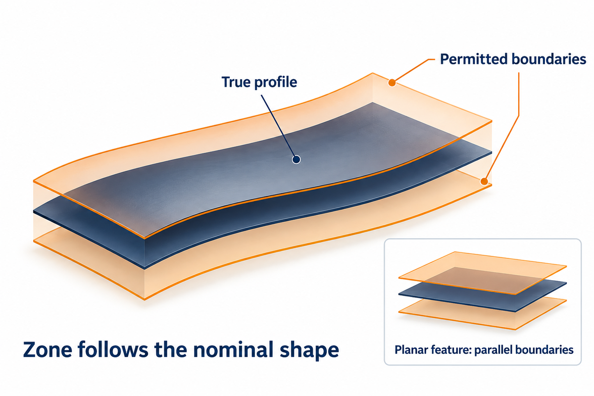
Profile of a surface controls conformity to the theoretically exact shape of a specified surface. The profile tolerance zone follows that shape, whether it’s flat, cylindrical, or free form. The actual surface must be within the permitted limits. Datums, basic dimensions and modifiers determine which relationships the requirement also controls.
The profile of a surface symbol is an arc closed by a straight line at its base. It’s different from the open arc used for profile of a line. The GD&T symbol is in the first compartment of the feature control frame; the tolerance value and applicable datum references follow. The leader and extent indicators of the frame must be read with the requirement.
A curved surface requires boundaries that follow its true profile. This 3-dimensional tolerance zone around a surface changes direction with the nominal geometry. Treating every surface profile tolerance zone as two flat planes would discard the freeform geometry. The picture of parallel planes is applicable to a planar surface feature and not to every profile surface.
ASME Y14.5 and ISO 1101 belong to different specification systems. Identify the standard and edition invoked by the drawing. Similar symbols do not necessarily indicate that all interpretation rules are interchangeable.
Total tolerance is not the deviation on each side
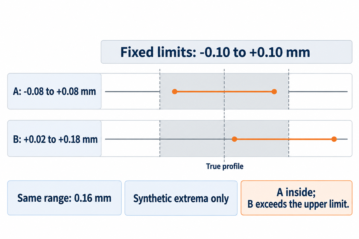
A number in a surface callout gives a total tolerance width, as illustrated in Hexagon’s equal-bilateral example. When the zone is equally disposed about the true profile, half is on either side of the nominal surface. A 0.20 mm surface tolerance therefore gives nominal limits of −0.10 mm and +0.10 mm. It doesn’t allow ±0.20 mm.
How to calculate the profile of a surface?
Define the zone boundaries, establish the permitted alignment and evaluate the measured surface against those boundaries. For a fixed, equally disposed zone, compare signed deviations with minus and plus half the stated tolerance. A reported profile result may use a different numerical convention; identify that convention before comparing it with the drawing.
Signed-Limit Acceptance Demonstration
The Signed-Limit Acceptance Demonstration reveals deviations concealed by the peak-to-valley value by comparing signed extrema to fixed limits.
| Set | Minimum, mm | Maximum, mm | Range, mm | Geometric comparison |
|---|---|---|---|---|
| A | −0.08 | +0.08 | 0.16 | Inside |
| B | +0.02 | +0.18 | 0.16 | Outside upper limit |
| C | −0.18 | −0.02 | 0.16 | Outside lower limit |
| D | −0.05 | +0.05 | 0.10 | Inside |
| E | −0.11 | +0.01 | 0.12 | Outside lower limit |
| F | −0.01 | +0.11 | 0.12 | Outside upper limit |
| G | −0.09 | +0.09 | 0.18 | Inside |
| H | −0.10 | +0.10 | 0.20 | On both boundaries |
| I | +0.03 | +0.07 | 0.04 | Inside |
Consider a hypothetical contoured cover located by an established datum reference frame. The inspection program retains that alignment. Set A spans 0.16 mm and stays inside the zone. Set B also spans 0.16 mm, but its upper extreme exceeds the boundary by 0.08 mm. Recentring B could make its variation appear acceptable, yet that movement is unavailable under this fixed requirement. A quality engineer should retain the signed extrema and investigate the offset before approving the cover. The example isolates geometry; sampling and measurement uncertainty still have to be settled before a final conformity decision.
Datums determine how the profile zone is constrained
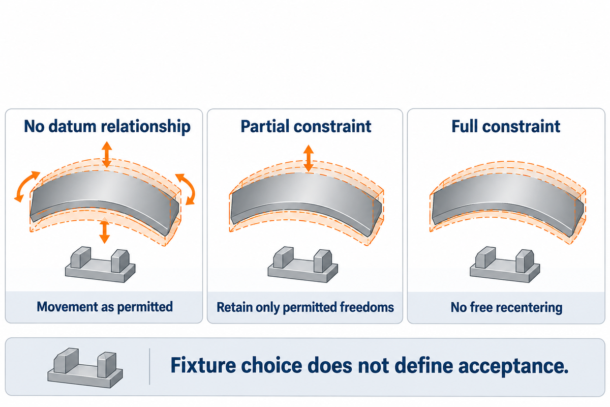
Datum references position the profile zone in relation to other features and restrict its permitted movement. Partially constrained conditions allow some degree of freedom; completely constrained conditions don’t. Read the profile of a surface callout as a complete requirement; the number of datum letters alone won’t indicate all remaining translations and rotations.
Can profile of a surface be used without a datum?
Yes. Profile control without any datums is a valid specification when the required surface geometry doesn’t require a datum relationship. The nominal geometry defines the zone. Depending on the surface and extent, the requirement can constrain size and form; “no datums means form only” isn’t always the case.
Alignment-to-Acceptance Comparison
The Alignment-to-Acceptance Comparison separates permitted zone movement from measurement set-up so teams agree on what the measurement result actually evaluates.
| Inspection question | No datum relationship | Partial constraint | Full constraint |
|---|---|---|---|
| What defines shape? | True profile | True profile | True profile |
| What defines location? | No external datum relationship | Specified datum constraints | Established datum frame and basic geometry |
| Can the zone translate? | As permitted by the requirement | Only in remaining freedoms | No free recentering |
| Can the zone rotate? | As permitted by the requirement | Only in remaining freedoms | No free rotation |
| Does a fixture define acceptance? | No | No | No |
| What must the programmer document? | Fit method and controlled extent | Datums, order and retained freedoms | Datum establishment and fixed evaluation |
| What should quality compare? | Result against the permitted zone | Result after constrained fitting | Result in the specified frame |
| What must purchasing request? | Declared evaluation convention | Evidence of the specified alignment | Reproducible datum-based report |
| What resolves disagreement? | Drawing interpretation and fit settings | Review of missing or added constraints | Review of datum establishment and offsets |
A curved housing seats against a mounting face and locates on two other features. The designer specifies a datum sequence because the mating assembly requires that relationship. An inspector first aligns the part for safe probe travel, then evaluates the profile using the drawing’s datum constraints. These are two separate activities. Best fitting only the curved part may give the wrong mount relationship if the fit ignores the datum constraints defining the mount relationship. When evaluating the fit of a part, a manufacturing engineer should determine if the part is being evaluated as it was intended to be assembled; if movement of the part is allowed, don’t give up that freedom for the sake of convenience.
Actual datum features also contain form error. Research by Craig Shakarji and Vijay Srinivasan of NIST on how definitions of datum-fitting behave on imperfect cylindrical features relates to this. That research isn’t a replacement of the standard being invoked, but it explains why the software instruction is incomplete: “use datum A.” If the part contains a form error, record how the software establishes the datum instead of recording that error in the part feature control frame. Diagnose CMM datum errors before going through the inconvenience of modifying the drawing.
Basic dimensions and CAD define the true profile
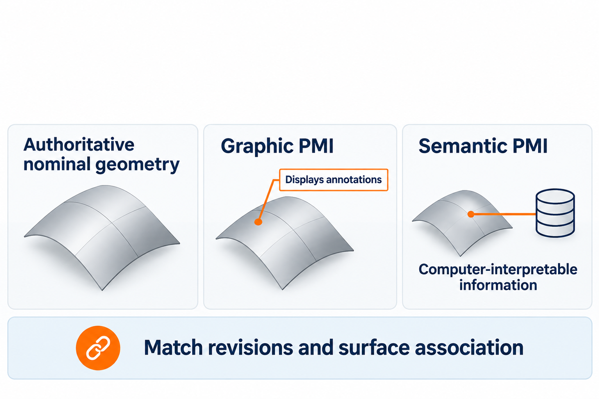
Theoretically exact geometry has exact dimensions. Variation is allowed. The profile control defines how much. A model can specify the nominal profile of the surface when the product definition makes that model authoritative. The drawing and model revision must agree, and the inspection program must contain enough information to identify the indicated surface and its limitations.
Don’t add a separate tolerance to a basic dimension for the contour description alone. Use the profile requirement to identify permitted variation around features described by basic dimensions. Check the drawing tolerance boundaries, including which general notes apply. A basic dimension and a toleranced size dimension describe different things.
NIST recognizes that semantic PMI in a STEP file is computer-interpretable, while graphic PMI displays in STEP files only show the annotations. A visible GD&T callout in a viewer therefore does not prove that an inspection application has imported its meaning. Check the profile of surface callout, datum identifiers and surface association after transfer.
Surface profile versus line profile and flatness
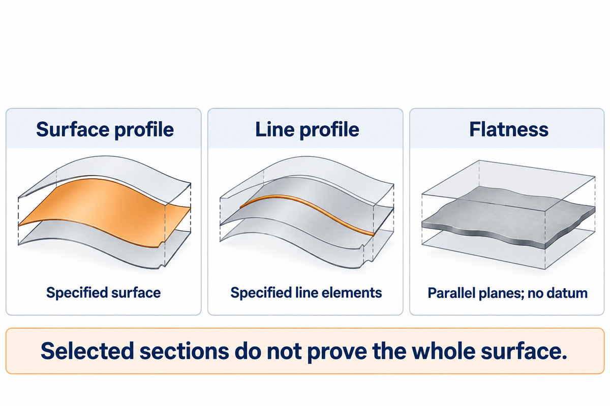
Flatness is for surfaces between two parallel planes without a datum reference. Line profile is for defined line elements in sections. These GD&T controls answer different geometric questions, even when the inspected part looks similar.
What is the difference between a surface profile and a line profile?
Surface profile applies a three-dimensional tolerance zone to the specified surface, while a line profile tolerance applies two-dimensional zones to the applicable line elements. A line profile control therefore requires attention to section direction and extent. A surface-profile requirement also applies between the sections, so those regions need coverage too.
| Need | Control to consider | Interpretation to resolve |
|---|---|---|
| Freeform skin relative to mounting features | Surface profile with relevant datums | Nominal model, extent and alignment |
| Specified section contours | Line profile | Section direction and applicable elements |
| Flat face independent of other features | Flatness | Surface extent and form evaluation |
| Flat face at a defined basic location | Surface profile with suitable constraints | Location, orientation and zone definition |
Coverage of Line and surface requirements also differs. Either of the profile controls describes a nominal contour. For a line or profile inspection requirement, identify whether the drawing controls a surface or line before programming measurements. A surface control can’t be fulfilled by selected sections without resolving the coverage deficit. A separate guide to flatness and straightness zones covers this in more detail.
Unequal and composite profile callouts need separate interpretation
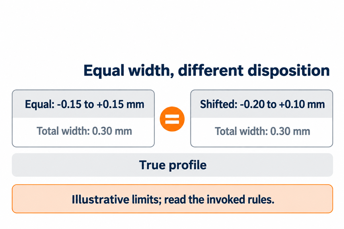
An unequally disposed profile zone shifts the permitted boundaries relative to true profile, without changing its stated total width. A composite profile requirement incorporates related levels of control. Neither should be treated as an ordinary plus/minus pair of dimensions, or defaulted to an equal-zone calculation.
For example, limits of −0.20 mm and +0.10 mm enclose a 0.30 mm total zone. They aren’t equivalent to ±0.15 mm, although the total width is identical. Determine which side is positive from the defined surface direction and the specification. A single tolerance range cannot show where the zone is shifted.
In a 2021 comparison of ISO GPS and ASME tolerancing, Zbigniew Humienny examined differences including profile-zone disposition and composite requirements. The ASME unequally disposed profile symbol and ISO UZ notation should not be translated by appearance alone. Likewise, a composite frame and a stack of individual frames require interpretation. Resolve the invoked rules before trying to refine the surface requirement in inspection software.
CMM measurement starts with the specified alignment

A coordinate measuring machine inspects measured surface data against nominal geometry using required alignment and mathematical method. Outcome depends on access to probing points, point distribution, and settings. Arrange measurements along the surface to cover as many process and geometric risks as possible. A cluster of points in a region doesn’t establish the condition of an adjacent or unmeasured region.
How to check the surface profile?
Establish the nominal definition, controlled extent and datum constraints, measure representative surface data, evaluate the data using the declared method, and report the outcome with its bounds and coverage. The acceptance decision must also follow the applicable treatment of measurement uncertainty, especially near a tolerance boundary.
- Confirm the product definition. Match drawing, model and standard revisions.
- Mark the surface extent. Identify boundaries, exclusions and inaccessible regions.
- Establish the alignment. Apply datum precedence and retain only permitted freedoms.
- Evaluate the measured data. Record sampling, fit method and any filtering.
- Apply the acceptance rule. Compare the reported characteristic with its limits and document uncertainty treatment.
NPL’s CMM Measurement Strategies guide identifies point selection, alignment, temperature, cleanliness and surface condition as measurement-strategy considerations. Use the factors while planning geometric inspection evidence. Set the point count from these factors and from where the contour changes, not from a fixed minimum.
Consider a machined blend between a broad curved wall and a narrow transition. A sparse grid on the broad surface may overlook a local ridge in the blend. Adding points to the same broad area doesn’t resolve that. The programmer should place more measured values in areas where there’s a change in the geometry or where the machining process can leave a local error. If the probe doesn’t reach the transition, note the gap and agree on other means. The quality lead then knows which part of surface profile control has evidence and which part is still open. A smooth interpolated colour map should not fill that evidential gap.
Inspection reports need limits as well as colour maps
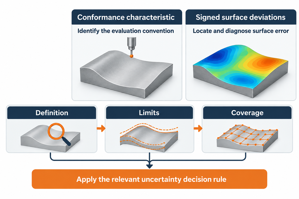
The GD&T profile tolerance report identifies the characteristic, the evaluation scheme, and the limit. Signed deviations help locate surface error; a scalar profile result can also be valid. The two cases shouldn’t be interchanged. Provide enough information to decipher whether a result is conformity or variation.
The publisher’s introduction to ASME Y14.5.1-2019 describes a zone-based actual-value definition for direct comparison with the specified tolerance. Don’t assume every program reports twice the largest absolute deviation, or that maximum minus minimum is always the acceptance value. Ask which mathematical definition produced the number.
In his discussion of measurement reporting, Dean Watts, chair of ASME Y14.45, distinguishes conformance data from supplemental surface-deviation information. Both have a role, but they answer different questions.
Dean Watts, Quality Magazine, April 2024; paraphrased.
Record the positive and negative extrema when they assist in diagnosing the surface, along with the model revision, alignment and measured extent. Leave the scale limits of the color maps visible. A display automatically rescaled for each part can make unequal deviations look similar.
ISO 14253-1:2017 addresses decision rules for proving conformity or nonconformity while accounting for measurement uncertainty near specification limits. Apply the rule invoked by the contract and specification system; do not silently impose an ISO rule on every ASME drawing. A result on a geometric boundary needs that decision context before release. The guide to uncertainty at a tolerance limit develops this distinction.
Drawing and inspection handoff before a machining quote
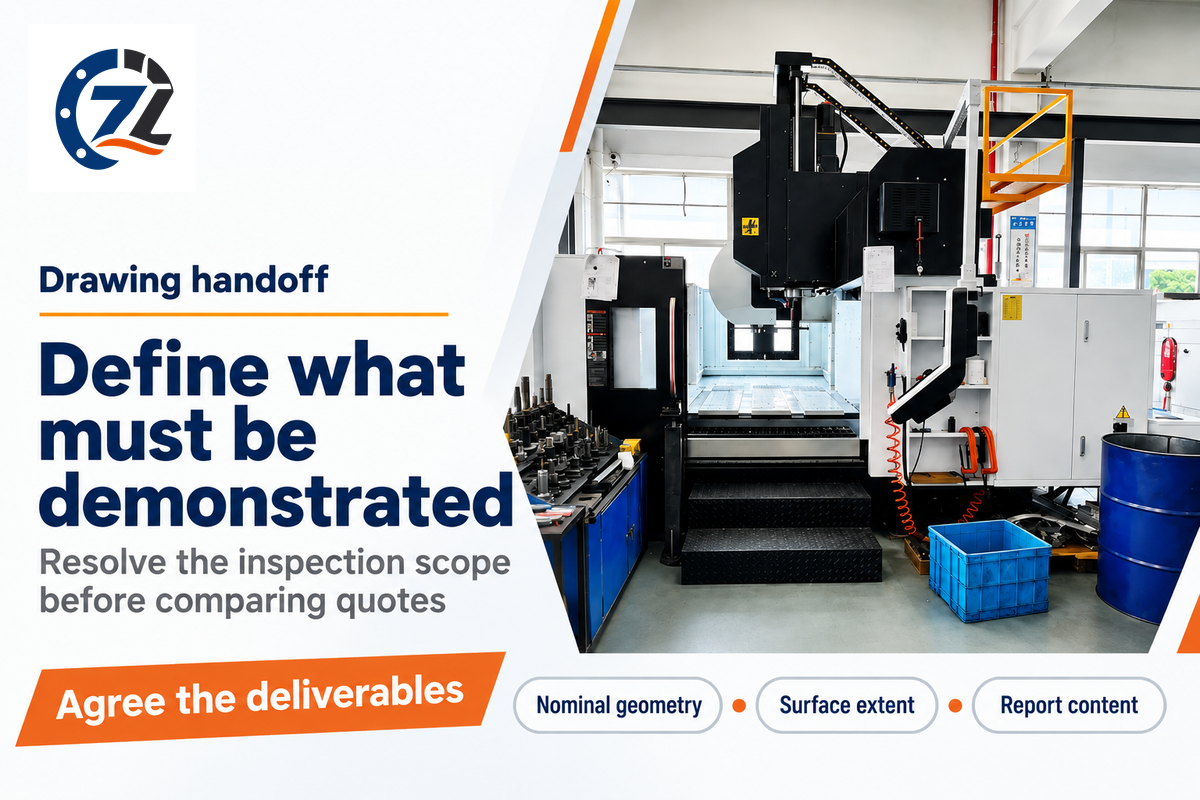
Reach agreement on nominal geometry, controlled surface and inspection deliverables prior to requesting a machining quote. They’ll define what the supplier must machine and demonstrate. A profile of a surface tolerance without a usable model, clear extent or reproducible datum interpretation leaves quoted work open to differences in interpretation. Confirm the tolerance applied to each controlled region.
| Open issue | Decision owner | Required handoff |
|---|---|---|
| Drawing and model conflict | Design authority | Authoritative revision and corrected definition |
| Datum interpretation differs | Design and quality | Agreed constraints and evaluation setup |
| Region cannot be probed | Quality and manufacturing | Alternative method or explicitly unresolved coverage |
| Finishing changes geometry | Design and manufacturing | Required inspection stage |
| Report formats differ | Quality and procurement | Characteristic definition, limits and deliverables |
| Result approaches a limit | Quality and customer | Applicable conformity decision rule |
Key takeaway
A 0.20 mm equally disposed profile zone allows 0.10 mm on each side; acceptance still depends on the specified alignment, measured coverage and decision rule.
Use the drawing checklist to prepare the drawing for quotation including inspection information that goes with the finished part.
Frequently asked questions
Is a 1.0 mm profile zone a sphere or a cube?
A profile zone follows the nominal surface; it is not a general cube-shaped allowance.
For an equally disposed 1.0 mm profile requirement, the boundaries lie 0.5 mm to either side of the true profile. A sphere-envelope construction helps explain the zone around a curved nominal surface, but the resulting boundaries follow that surface. Don’t apply an independent 1.0 mm coordinate allowance along each axis. The defined geometry and zone disposition govern the permitted variation.
How many points do I need to measure for a surface profile?
Plan enough points to cover the whole controlled extent, and add more where the geometry changes or machining can leave a local error.
Select coverage around the nominal geometry, expected manufacturing errors, accessible regions and required confidence in the result. A local tool mark can fall between discrete points, while repeated points in one area leave another area unexamined. Document the sampling strategy and unresolved regions. Increasing point density can improve evidence, but it doesn’t turn an incomplete measurement into proof of the full surface.
How does surface profile interact with surface roughness?
Profile and roughness address different characteristics and may both require specification.
A surface can remain within its profile zone while having unsuitable texture for sealing, friction or appearance. Conversely, a smooth finish can still sit outside the profile zone. Specify the relevant texture requirement separately, and define the inspection stage if coating or finishing changes the geometry. The surface finish result shouldn’t be substituted for the profile result in an acceptance report.
Does a profile callout cover every face of a baseplate?
Not by default; the callout controls only the face or extent the drawing indicates.
Read the leader, surface boundaries and applicable extent notation. A profile of surface tolerance on one indicated face doesn’t automatically apply to the entire part. Resolve ambiguous coverage before inspection.
Can a CAD model define the nominal profile?
Yes, when the product definition identifies the authoritative model and its applicable requirements.
The model must provide the intended geometry, while the drawing or model-based definition supplies the tolerance and datum relationships. Match revisions and check the surface association after import. Confirm the receiving software imported the callout’s meaning, not just its visible annotation. If the model and drawing disagree, obtain a corrected authoritative definition rather than selecting whichever geometry gives a better measurement result. Keep the resolved revision with the inspection program and report.
Can profile tolerance control location?
Yes, when the specification constrains the zone’s location relative to the relevant datums.
Read the basic geometry and datum references together. A datum-free callout doesn’t establish that external location relationship. A positional tolerance and a surface profile requirement shouldn’t be exchanged without reviewing their different targets and zones.
Is profile of a surface required on every machined contour?
No; the control should express the functional requirement of the part.
The use of a profile tolerance is appropriate when a complex contour or its relationship to other features needs a defined zone. Other features can require size, form, orientation or location controls of their own. Adding a profile symbol without defining the nominal surface and extent doesn’t resolve an incomplete drawing. Choose the requirement around fit and function, then ensure that manufacturing and inspection can interpret the same product definition.
Technical basis: Numerical sets in the Signed-Limit Acceptance Demonstration are synthetic teaching examples, not Zhenling production measurements or capability claims. Standard references use publicly accessible scope and publisher descriptions; the invoked drawing standard and edition govern individual parts.
References and sources
- ASME Y14.5: Dimensioning and Tolerancing.
- ISO 1101:2017, geometrical tolerancing scope.
- ASME Y14.5.1-2019, mathematical definition introduction.
- NIST: A Conceptual Data Model of Datum Systems.
- NIST: computational investigations of datum definitions.
- NIST STEP File Analyzer and Viewer: semantic and graphic PMI.
- Humienny, 2021: Can ISO GPS and ASME Tolerancing Systems Define the Same Functional Requirements?
- NPL: CMM Measurement Strategies.
- Watts, 2024: Better Measurement Data Reporting to Improve GD&T Effectiveness.
- ISO 14253-1:2017, conformity decision rules.