Flatness vs Straightness: Tolerance Zones, Features and Inspection Choices


The practical difference between flatness and straightness is the feature being controlled. Identify a line, derived axis, or full face for a flatness vs straightness decision. A plate may pass a straight-line check in two directions and still be twisted. Start with the mating function and evaluate the feature on the drawing, then choose an inspection that reflects the zone of interest.
Key takeaway
Surface straightness gives each specified line its own two-line zone; surface flatness puts the whole face in one two-plane zone. Axis straightness addresses a different feature. A 0.02 mm callout cannot be interpreted correctly until its attachment and zone shape are clear.
Flatness vs straightness at a glance
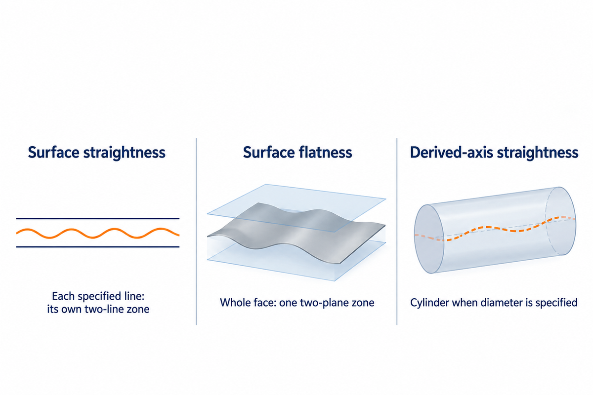
Straightness and flatness are two form controls that restrict deviations from ideal geometry; surface straightness focuses on controlling individual line elements. Surface straightness addresses a line, whereas flatness addresses the entire surface within a two-plane tolerance zone rather than a cylindrical tolerance zone. As for the difference between straightness and flatness, that concern is taken care of through attachment before any instrument is chosen.
As Gyula Hermann’s 2007 paper on form-tolerance assessment notes, geometry is described through parallel bounding lines and planes. That mathematical distinction is useful; the paper’s historical standard reference isn’t to be read as a current modifier rule. Our GD&T symbols guide places these two GD&T symbols among the wider controls of geometric dimensioning and tolerancing.
Feature, Zone, Evidence Comparison
| Decision | Surface straightness | Surface flatness | Derived-axis straightness |
|---|---|---|---|
| Controlled feature | Individual line element | Indicated face | Derived line of a size feature |
| Typical zone | Two parallel lines | Two parallel planes | Cylinder when diameter is specified |
| Shared evaluation | Within each specified section | Across the complete face | Along the derived feature |
| Useful function | Directional contact path | Broad mating contact | Shaft or bore form along length |
| Drawing attachment | Surface and direction | Surface identification | Feature-of-size identification |
| Sampling layout | Traces in required direction | Points or scans across area | Sections needed to derive the line |
| Datum relationship | No datum reference for this form control | No datum reference for this form control | Separate from location or orientation control |
| Reporting requirement | Trace locations and line evaluation | Area coverage and plane evaluation | Extraction and cylindrical evaluation |
| Common confusion | Passing two directions treated as whole-face acceptance | Height sweep treated as flatness automatically | Surface readings substituted for derived-axis data |
To interpret a requirement stating “0.02 mm” identify whether 0.02 mm separates two lines, two planes or defines a zone diameter. Buying an indicator with higher resolution wouldn’t answer that question. Keep zone description next to requirement to enable comparing to the same requirement during purchasing and quality inspection.
Surface straightness controls individual line elements
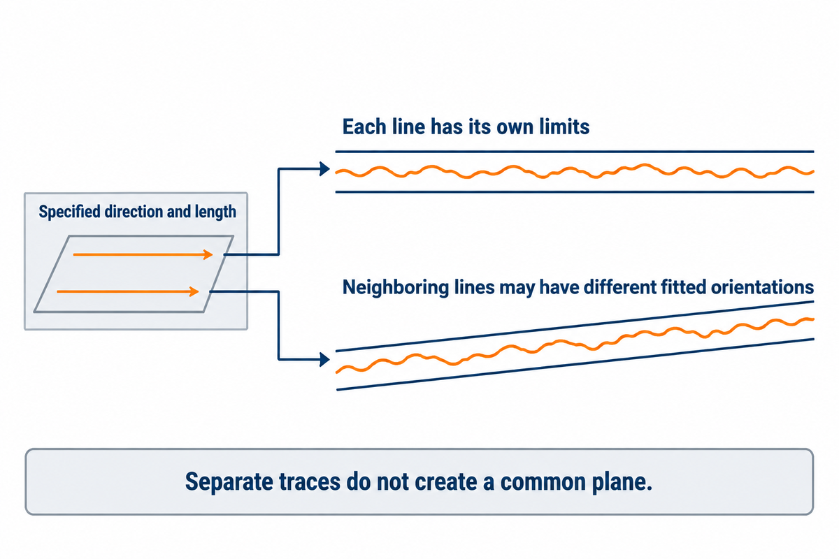
A surface callout is used to control the straightness of a surface line within a specified tolerance. Conforming straightness ensures that a line is sandwiched between its adjacent parallel boundaries. Each evaluated element of the surface must lie within those limits. The straightness tolerance zone doesn’t automatically merge separate traces into a single common plane; therefore, other checks such as broad-face seating may be required.
The public preview of ISO 12780-1:2011, clauses 3.2.1 and 3.3.1.1, distinguishes an extracted line from minimum-zone reference lines. Those reference lines enclose the profile with the least separation. Its scope covers complete profiles of integral features, and does not license treating a shaft’s derived axis as a common surface trace.
When should we specify straightness control on a surface?
Use straightness when the functional requirement will follow a particular direction or contact path. Straightness is applicable to a longitudinal element of the surface along a guide, which may need a separate line requirement even when a broader face requirement also exists. Define the controlled direction and length. Straightness applied without any clear attachment leaves the inspector to guess which traces are of concern. A straightness tolerance value specifies how much the surface line may depart from straight geometry. The specified extent tells the inspector where to evaluate it.
For a 100 mm guide path with an illustrative 0.02 mm straightness tolerance, the extracted line has to lie within the tolerance zone specified along that path. A neighboring line may have a different fitted orientation. If the purchase requirement instead is for seating across a 100 mm face, the whole-face control also needs to be defined.
Axis straightness changes the feature and tolerance zone
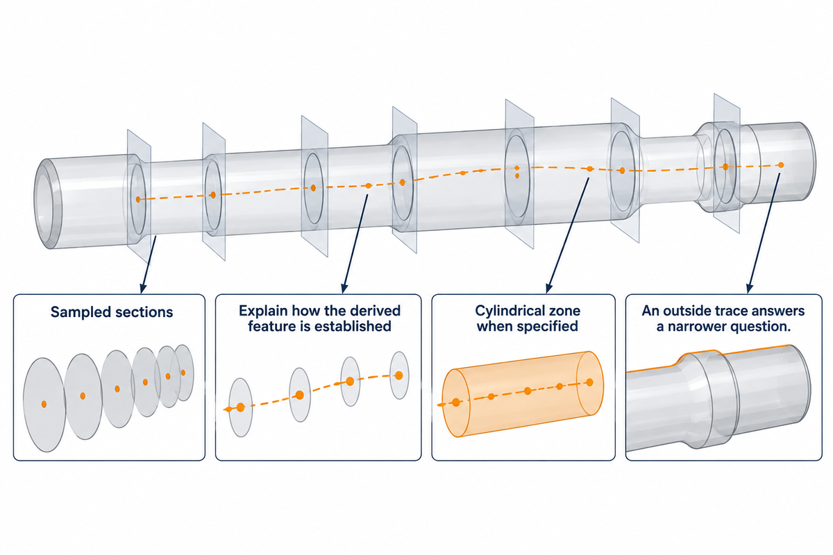
Straightness can apply to a derived axis rather than a visible line scratched along a shaft. Where the callout specifies a diametrical zone, the derived axis must lie in that cylinder. Surface straightness control is not a substitute for derived-axis straightness, because surface irregularities and the method used to derive the axis affect different quantities.
Check if straightness is applied to a surface or axis before interpreting a diameter sign or material modifier. For a derived-axis straightness measurement, the inspection plan must explain the sections sampled and how their centers or other specified derived features are established. One indicator trace along the outside of a round part answers a more restricted question.
Scope is also important for material-condition rules. The ISO 2692:2021 catalogue limits its material requirements to relevant linear features of size, including cylinders and opposed parallel planes. Hence a size tolerance and a geometric requirement must be read together when the invoked system demands it. Our ASME Y14.5 vs ISO 1101 comparison explains why rule sets should remain separate.
A 0.02 mm cylindrical zone describes a diameter, while a 0.02 mm surface-line zone describes separation of parallel lines. Quoting either value as a “straightness accuracy” generic term hides the feature that’s being assessed. Request the feature definition and evaluation method prior to evaluating inspection costs or accepting a substitute measurement.
Flatness controls the complete surface form
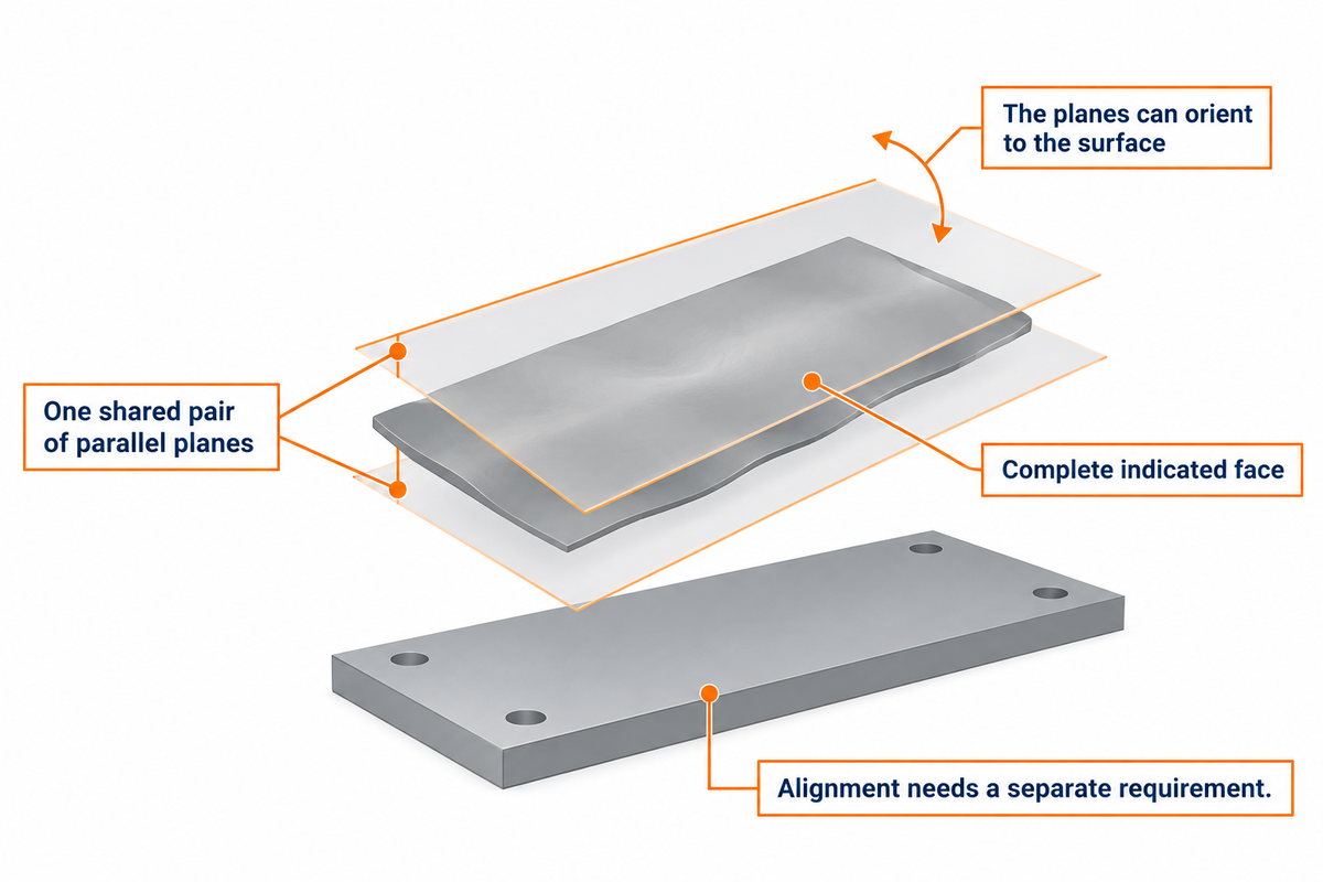
Flatness control states that the indicated surface has to fit within two parallel planes separated by the limit. Every part of that face belongs to the same flatness tolerance zone. The planes can orient to the surface; their orientation to another part feature needs a suitable separate requirement, such as parallelism.
The planar shape of a surface determines its own flatness regardless of how far it’s above a machine table. Evaluate the flatness of a surface over the indicated extent. Flatness is related to the form of a surface: a flat surface may still be tilted relative to its mount. Hermann’s section 3 explanation of plane-zone geometry clarifies the boundary. Straightness and flatness in GD&T need report definitions. Straightness tolerancing can assess multiple individual traces, but those independent fits do not ensure that the entire surface fits one pair of planes.
How to show flatness on a drawing?
Attach the flatness symbol and tolerance value to the appropriate face using the drawing conventions of the declared standard. Show the surface extent and specify any restrained condition. Ordinary surface flatness is typically shown without a datum reference; orientation control must be shown when the face must align with another feature.
When a face has a 0.02 mm flatness callout, the surface must lie within a 0.02 mm plane zone. A face may be sufficiently planar to satisfy the requirement. When the assembly also requires alignment to a mounting face, use the appropriate relationship control; reducing the flatness tolerance value doesn’t ensure that alignment.
Why passing line checks can miss a twisted surface
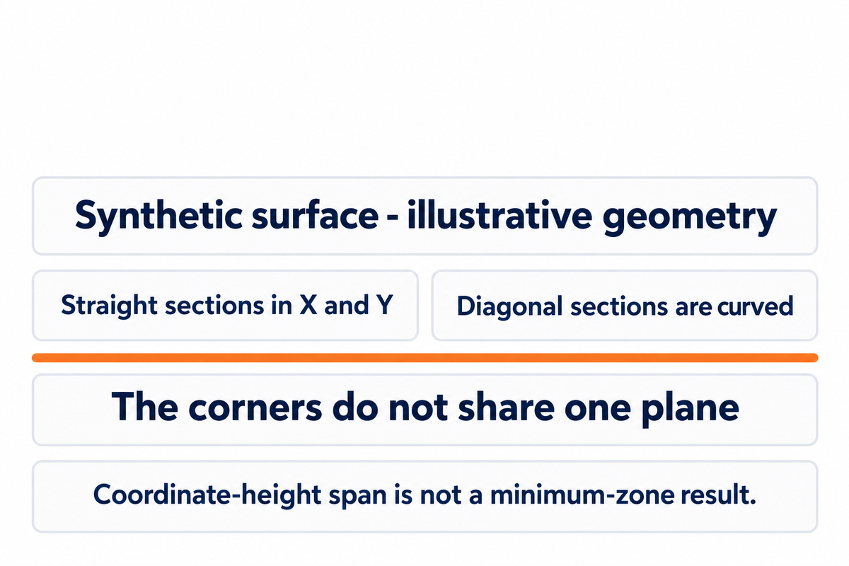
Twist can be present even if orthogonal straightness checks show zero displacement. Each trace can occupy its own straight line zone. A face with a saddle shape provides an example of a whole face check. In this case, straight sections are present in both the X- and Y-directions; the heights at the corners can’t be in the same plane.
Shared-Zone Twist Demonstration
Consider a synthetic 100 mm by 100 mm surface centered at the origin, with coordinates from −50 mm to +50 mm. Define its height by z = 0.000012 × x × y, using millimeters for all coordinates. At x = 50 mm and y = 50 mm, z = 0.000012 × 50 × 50 = 0.03 mm. Changing either coordinate’s sign changes the height’s sign.
| Point class | X (mm) | Y (mm) | Z (mm) | Interpretation |
|---|---|---|---|---|
| Positive corner | −50 | −50 | +0.03 | One end of a rising row |
| Edge midpoint | 0 | −50 | 0 | Midpoint lies on that row |
| Negative corner | +50 | −50 | −0.03 | Opposite row endpoint |
| Edge midpoint | −50 | 0 | 0 | Central row remains level |
| Center | 0 | 0 | 0 | Zero crossing of both central traces |
| Edge midpoint | +50 | 0 | 0 | Central row remains level |
| Negative corner | −50 | +50 | −0.03 | One end of the reversed row |
| Edge midpoint | 0 | +50 | 0 | Midpoint lies on that row |
| Positive corner | +50 | +50 | +0.03 | Opposite row endpoint |
If x is held constant, then z is a linear function of y. If y is held constant, then z is a linear function of x. The diagonal sections are different. Along y = x, the equation becomes z = 0.000012 × x², a curve. “Straight in x and y” shouldn’t become “straight in all directions.”
Looking at some other examples of surface shapes reveals the missing shared plane. For a plane written as z = ax + by + c, the sums of the heights at opposite corners of the rectangle must be equal. Here, one pair sums to +0.06 mm and the other to −0.06 mm. Therefore, the four corners aren’t in the same plane.
The difference between the maximum and minimum listed heights is 0.03 − (−0.03) = 0.06 mm. This is a coordinate-height span, not a claimed minimum-zone result. To assess a flatness tolerance, evaluate a common pair of planes using the specified method. The 1989 minimum zone study of Traband and others offers insight into why the assessment algorithm is important after the points have been measured.
How to measure straightness and flatness
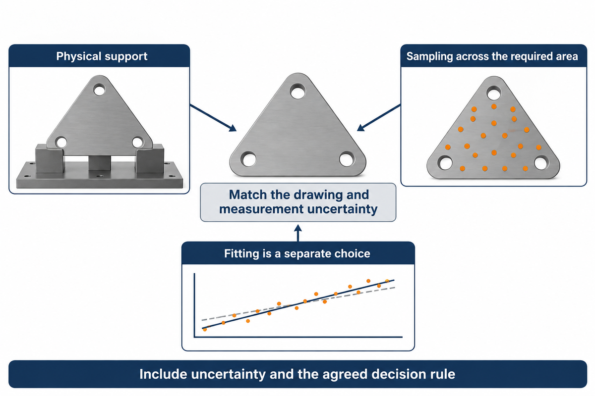
Measure straightness along the specified traces or derived features and measure flatness over the specified area, with common evaluation and physical support. In both cases, document physical support, sampling and fitting. A numerical result becomes meaningful only when those choices match the drawing and the measurement uncertainty supports the intended conformity decision.
How do you measure flatness?
When measuring the flatness of a face, acquire points on the surface with a suitable instrument, distribute them across the required area, and compare them with the defined criterion of a plane-zone. Data of an area can be collected and evaluated by a coordinate measuring machine. An indicator can also help to define a method. Placing the part on a surface plate and sweeping its upper face, however, can combine form with orientation to the support, so that sweep alone is not a flatness result.
George Schuetz, in his 2013 metrology column, illustrated placing the measured face down on the surface plate and contacting that surface through a hole. That arrangement is different from resting the opposite face on the plate and scanning the top. The latter can combine form with orientation relative to the support.
“some areas might be missed”
Support deserves its own entry in the report. A thin component can change shape under gravity, clamping or probe force; deformation caused by measurement pressure can alter the reading. ISO 10579’s published scope specifically concerns non-rigid parts requiring restraint during verification. Use the agreed condition and record it; our guide to specifying support and restraint during measurement develops that decision.
Sampling and fitting are separate functions. The 2013 NIST paper on least-squares fitting points out that representative sampling is different from selecting the appropriate fitted geometry. More points on the same narrow track can miss other regions. Conversely, broad coverage doesn’t correct a software setting that’s evaluating other features.
Near the acceptance boundary, include measurement uncertainty and the agreed decision rule. ISO 14253-1:2017 addresses that problem in its public scope. For an illustrative 0.02 mm limit and a measured result close to 0.02 mm, comparing the two displayed numbers alone can leave conformity unresolved. Report the uncertainty basis rather than inventing a universal margin.
For a 100 mm by 100 mm face, record the length and width of the surface sampled, plus the trace spacing in millimeters. Keep raw points where the reporting contract requires them, together with alignment and filtering settings. The wider inspection planning for the controlled feature guide assists with relating the tasks to tools available.
Choose the control and agree the inspection handoff

Select a straightness or flatness tolerance from the functional contact requirement. Indicate how the supplier should demonstrate this. Use straightness for a narrow directional path. Use flatness for broad seating that requires a shared plane zone. Behavior along the shaft-axis requires a derived-feature interpretation. The quotation package should capture these differences during inspection and delivery.
A buyer may ask if reduction in traces would also lead to a decrease in inspection cost. Meaningful negotiation should focus on coverage and function of callouts and not alter their spirit and intent. For the synthetic 100 mm face, to check only the central 100 mm row would miss all the other nonzero corner heights. The plane zone around the ideal surface can be defined by boundaries equidistant from the ideal surface, chosen midway between them. A faster inspection needs a justified sampling plan for the actual part.
Complete the checklist, indicating values specific to the drawing, and provide with a quote request. The “Recommended range” column indicates required input and units; it doesn’t define permissive limits of machining.
| Parameter | Recommended range | Why it matters | How to verify |
|---|---|---|---|
| Feature and extent | Drawing length and width in mm | Separates line, area and derived feature | Marked drawing and feature identifier |
| Form limit | Specified limit in mm or µm | Defines zone separation or diameter | Callout copied with its attachment |
| Part condition | Agreed support positions in mm; restraint if specified | Controls deformation during inspection | Fixture sketch and setup record |
| Sampling | Agreed trace lengths and point spacing in mm | Determines area and feature coverage | Measurement program or point map |
| Evaluation | Declared fitting/filter settings and units | Connects measured points to the requirement | Software configuration and result definition |
| Acceptance | Reported uncertainty in mm or µm and agreed rule | Resolves decisions near the limit | Measurement report and decision-rule reference |
In conjunction with the standard edition and revision of drawing, have this checklist ready. Our engineering drawing tolerances guide provides a broader perspective on engineering drawings. Before requesting a machining quote from Zhenling Metal, mark the mating face or path and provide the required inspection condition so that the quotation is responsive to the function.
Industry Outlook: keep standards and digital inspection definitions attached
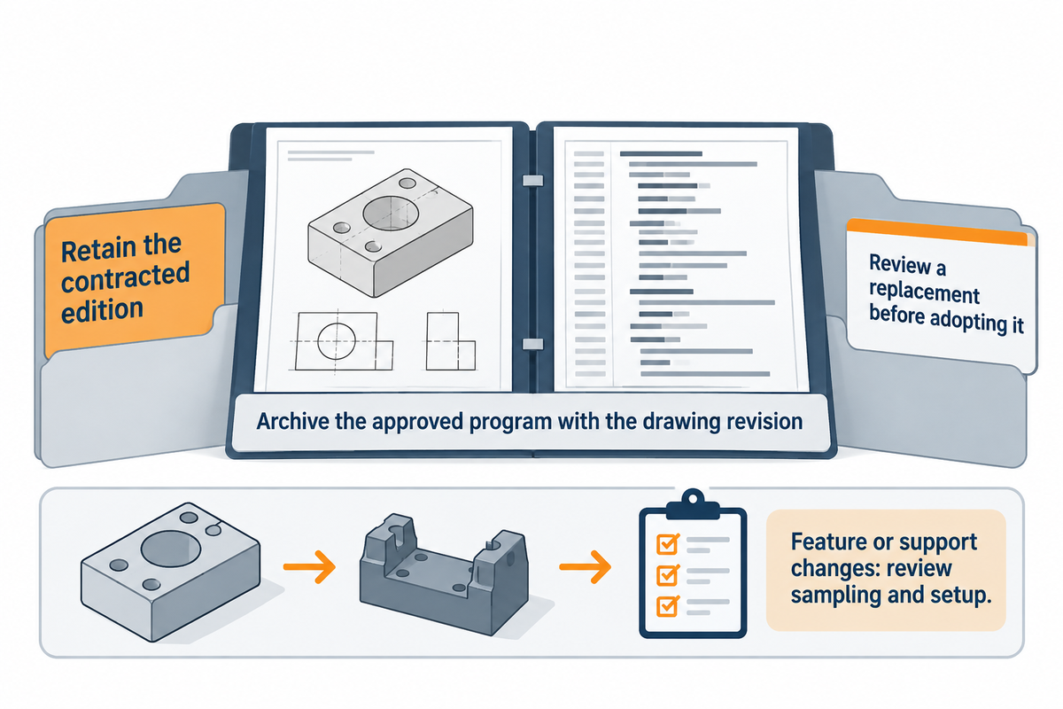
Standards development makes revision control a practical inspection issue: retain the contracted edition and review a replacement before adopting it. ISO’s published catalogue still identifies ISO 10579:2010 while listing ISO/DIS 25935 as a successor under development. A draft listing should trigger monitoring and technical review, rather than an automatic change to acceptance requirements.
At the October 2026 research check, the ISO 10579 catalogue marked the existing document for revision and showed the developing successor. For non-rigid parts, the useful purchasing action is to keep the specified restraint and inspection condition explicit now. When a replacement is published, compare its scope and requirements against the drawing contract before changing fixture instructions.
Digital inspection does not alleviate the responsibility to provide sufficient detail in the callout. The ISO 1101:2017 catalogue describes the language for geometrical specification and refers to attaching specifications to three-dimensional models under ISO 16792. A model-based callout still requires a defined feature and a readable requirement. Exporting a model without the associated context can leave the receiving party with a geometry model and an incomplete callout.
Digital reports and representations should capture the same distinction between points captured and forms assessed. The 2021 Quality article by Malburg, Mennuti and Zecchino illustrates how finer surface-detail expectations can greatly increase sampling demands. Its numerical examples describe the authors’ chosen assumptions; they are not a universal point-spacing prescription. Agree the relevant detail, measurement coverage and evaluation before treating a denser point cloud as an improvement.
For projects using ASME Y14.5-2018, reaffirmed in 2024, retain that edition identification through purchasing and inspection. Archive the approved program with the drawing revision. If a nominal 100 mm feature changes length or its support condition changes, review the sampling and setup instead of simply reusing the previous report template. This ensures the measured characteristic is connected to the feature which was intended by the designer.
Frequently asked questions
Does flatness include straightness?
Surface flatness constrains line elements within a common plane zone, but the drawing may also require a tighter directional straightness limit.
A line on a surface within this tolerance zone, extracted in an appropriate section, is bounded by the corresponding intersection. Separate control of individual line elements can still satisfy a more specific local requirement. Consider the function and scope of each requirement rather than eliminating one symbol because another is on the same face.
Do you need a datum for flatness?
Ordinary surface flatness does not reference a datum; its bounding planes are free to orient around the controlled face.
To state that a face is parallel, perpendicular, or located relative to a feature, a different control is required. Physical support is important during measurement, particularly for flexible parts. Contact between a fixture and feature does not become a drawing datum simply because the inspector used it to hold the part.
Can flatness and straightness be specified on the same face?
Flatness and straightness can address different functional requirements on one face when their directions, extents and limits are clearly specified.
For example, broad seating may require overall form control while a narrow travel path needs a tighter directional limit. Identify both requirements in the inspection plan and confirm the standard’s treatment of local and overall requirements. Duplicate callouts without a distinct functional reason can add inspection work while leaving the actual assembly concern unresolved.
What is a good flatness tolerance?
When a drawing invokes the general ISO geometrical tolerances, flatness over 30 to 100 mm is 0.1 mm for class H, 0.2 mm for K and 0.4 mm for L; a specified flatness limit follows the mating function, face size, material and assembly condition.
First consider the permitted functional gap, then assess process and measurement capability for the required geometry. A catalog tolerance for a short, stiff component may not be achievable on a wide, thin face, which can change shape under gravity, clamping or probe force.
What is flatness at maximum material condition?
Flatness at maximum material condition concerns an applicable feature-of-size requirement, which differs from ordinary flatness applied directly to one surface.
A flatness callout with MMC needs its feature attachment and governing rules checked prior to interpretation. Flatness with an MMC modifier should not be copied to any face, because the symbol looks similar. ISO 2692 limits its material requirements to relevant linear features of size, including opposed parallel planes. The practical inspection question is which derived feature must be evaluated and how its size-related requirements interact, rather than whether a simple top-surface scan looks flat against its supporting fixture.
Is flatness the same as coplanarity?
Flatness controls the form of an indicated surface; coplanarity concerns multiple features sharing a plane.
Separate flatness requirements on disconnected pads do not mandate a common height and orientation. To seat the pads together, a designer must use a combination specification. Review the form of each pad and their relationship to one another as depicted on the drawing.
How do you calculate straightness in GD&T?
Calculate straightness by evaluating the specified extracted or derived feature against its required zone and association rules.
For a surface line, the relevant two-line evaluation addresses the measured profile in the specified section. A diametrical derived-line requirement, on the other hand, mandates a cylindrical evaluation and any applicable material conditions. Maximum-minus-minimum readings from a random setup are not necessarily the required results. Record extraction, filtering and alignment, then confirm that the software’s reported characteristic matches the callout. A result without that method description can conceal a different measurement, even when its displayed units are correct and its arithmetic has been checked.
References & Sources
- Form-tolerance assessment, section 3 Gyula Hermann, Acta Polytechnica Hungarica, 2007.
- ISO 12780-1:2011 public preview extracted-line and minimum-zone terminology.
- Evaluation of straightness and flatness tolerances using the minimum zone Traband et al., 1989, public abstract.
- The Enduring Appeal of Least-Squares Fitting in Computational Coordinate Metrology NIST, 2013.
- Measuring for Flatness, Thickness and Parallelism George Schuetz, Modern Machine Shop, 2013.
- GD&T’s New Rule and What it Means for Measurement Malburg, Mennuti and Zecchino, Quality, 2021.
- ISO 2692:2021 material-requirement scope, official catalogue.
- ISO 14253-1:2017 conformity decision rules, official catalogue.
- ISO 10579:2010 non-rigid-part scope and development status, official catalogue.
- ISO 1101:2017 geometrical-specification scope, official catalogue.
- ASME Y14.5-2018 (R2024) edition and reaffirmation status, official catalogue.
ABOUT ZHENLING
Custom machining from drawings and samples
Shanghai Zhenling Hardware Co., Ltd. was established in 2006. Its Jiashan, Zhejiang factory covers an 8,000 m² site with a 6,000 m² workshop for custom machined metal parts.
The team works from drawings and samples for applications including pressure vessels, oil-gas separation, and fluid control. Material experience includes carbon, alloy, and stainless steels as well as special alloys.
- 3-, 4-, and 5-axis CNC machining
- Grinding, wire cutting, and welding
- Domestic and export divisions
CONTACT PROFILE
Company details
- NAME
- Shanghai Zhenling Hardware Co., Ltd.
- ESTABLISHED
- 2006
- LOCATION
- Jiashan, Zhejiang, China
- FOCUS
- Custom machined metal parts from drawings and samples
- CAPABILITIES
- 3/4/5-axis CNC machining, grinding, wire cutting, and welding
- CONTACT
- Share the drawing, material, quantity, and critical requirements.