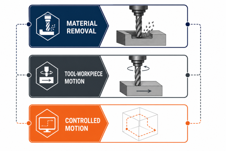
Turning is a type of machining process whereby a workpiece rotates while a cutting tool removes material along a defined path. A lathe uses this motion to make round diameters, shoulders and tapers as well as other features. The workpiece provides the rotational motion; the tool moves into or along the workpiece to provide the required shape.
A shaft that has a bore and an external thread and a cross hole would require several types of cuts. Outside turning creates the shaft diameter, a boring operation sizes the hole and threading forms the screw thread profile. The cross hole would require a drilling operation with suitable access. These differences would require different tools, setups and inspection work to be accounted for in a finished-part quote.
Turning at a glance
- Main motion: a rotating workpiece and a feeding, non-rotating cutting edge.
- Typical features: cylindrical surfaces, end faces, bores, tapers, grooves and threads.
- Planning inputs: material condition, drawing dimensions, surface requirements and order quantity.
Turning process: how the workpiece and tool move
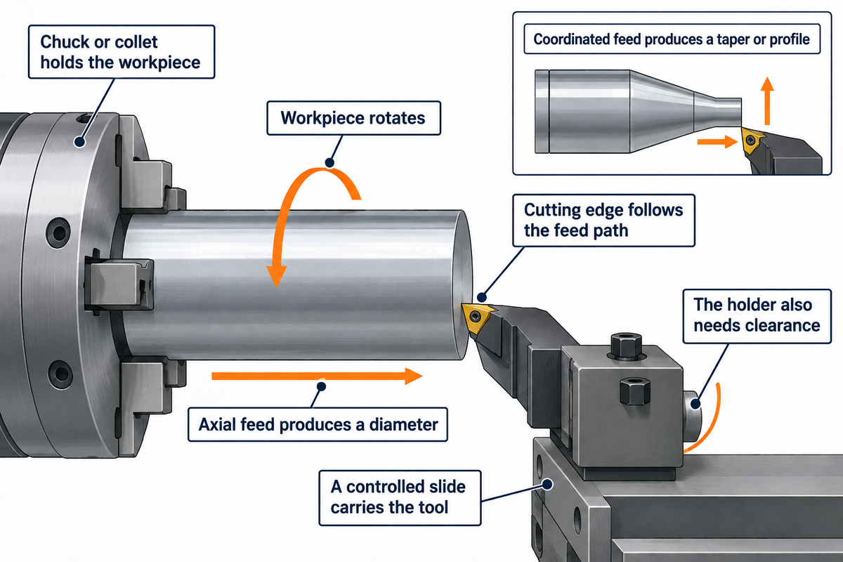
In traditional turning, a tool removes material as the workpiece surface passes the edge of the tool. Feed adjustment changes the tool position with respect to the surface. A diameter is produced by moving the tool along the spindle axis. A taper or curved profile is produced by moving the tool in a coordinated fashion across and along the axis. The cutting edge moves along the feed path and doesn’t spin with the workpiece.
The headstock drives the spindle and holds the workpiece in a chuck, collet or other fixture. A controlled slide or carriage carries the tool. In between the headstock and tailstock, a long shaft can be supported at its free end. The University of Arkansas turning Chapter outlines how these elements support the cutting motion.
The turning definition describes a process, and “lathe” names a machine tool. Woodturning implements a rotating workpiece principle, and metal machining implements different tooling and workholding. A rectangular blank can be held for machining, even though its corners initially create interrupted contact. Round stock usually avoids that extra interruption when the desired shape is a shaft or sleeve.
What is a turning tool used for?
A turning tool removes the excess material to create the outer shape, size or end face of a rotating part. The tool holder and the cutting edge must reach the feature to be cut without interference with the chuck, a shoulder, or an adjacent surface. Unlike a milling cutter with several teeth, a single-point tool has only one active cutting edge.
For a stepped pin, an external tool cuts the main diameter and a shoulder. A narrow tool reaches the retaining ring groove, and a threading insert follows the thread pitch. Using a material-compatible insert isn’t sufficient if the holder can’t reach the feature. The drawing must leave room for the tool body as well as its edge.
Turning operations matched to part features
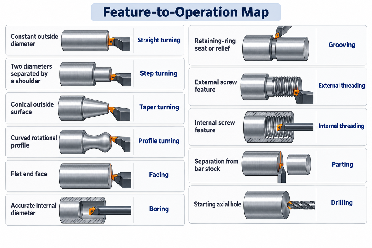
Match each feature with the cutting action that produces it before determining the number of setups required for the part. Straight turning produces an outside diameter, and facing produces an end face. Boring sizes an existing hole. Access to those surfaces determines which operations can be performed in the same setup and which require the part to be transferred or reversed.
Purdue’s lathe toolpath guide differentiates outside roughing and finishing from facing and internal machining. During facing, the tool moves across the end of the workpiece, perpendicular to its rotation axis. Outside turning cuts the outer surface of the workpiece. Boring begins on an existing opening, and the boring bar and cutting edge must fit inside it.
Feature-to-Operation Map
| Part feature | Operation | Planning or inspection point |
|---|---|---|
| Constant outside diameter | Straight turning | Measure diameter along the cut length to detect taper. |
| Two diameters separated by a shoulder | Step turning | Define both diameters and the shoulder position. |
| Conical outside surface | Taper turning | Specify the taper by angle or controlled diameters and length. |
| Curved rotational profile | Profile turning | Check the complete contour and tool-nose compensation. |
| Flat end face | Facing | Control axial length and the face relationship to the datum axis. |
| Accurate internal diameter | Boring | Provide a starting hole and clearance for the bar. |
| Retaining-ring seat or relief | Grooving | Specify groove width, depth and position. |
| External screw feature | External threading | Define thread form, pitch, fit and runout space. |
| Internal screw feature | Internal threading | Allow the threading tool to enter and exit the bore. |
| Separation from bar stock | Parting | Account for cut width, part support and the remaining end condition. |
| Starting axial hole | Drilling | Leave the required stock if boring or reaming follows. |
On a lathe, drilling and reaming are related operations rather than alternative names for outside turning. Form knurling presses a grip pattern into the surface instead of shaving the material away. Some knurling tools cut the grip pattern, so the specified method matters when material displacement or finished diameter affects the design.
Consider a sleeve with an outside bearing seat, a through-bore and a shoulder on the back face. The front face gives an axial reference. Roughing removes the majority of the outside material and drilling gives a path for the boring bar. Finishing the bore and bearing seat in a suitable common setup can help control their relationship. The shoulder still needs access for the tool. If the chuck covers that shoulder surface, the route needs a transfer or second setup, with a defined locating surface. A quote that includes only “turn diameter” misses part of the job. The buyer needs the complete sleeve geometry and its inspection requirements priced together.
CNC turning vs manual turning
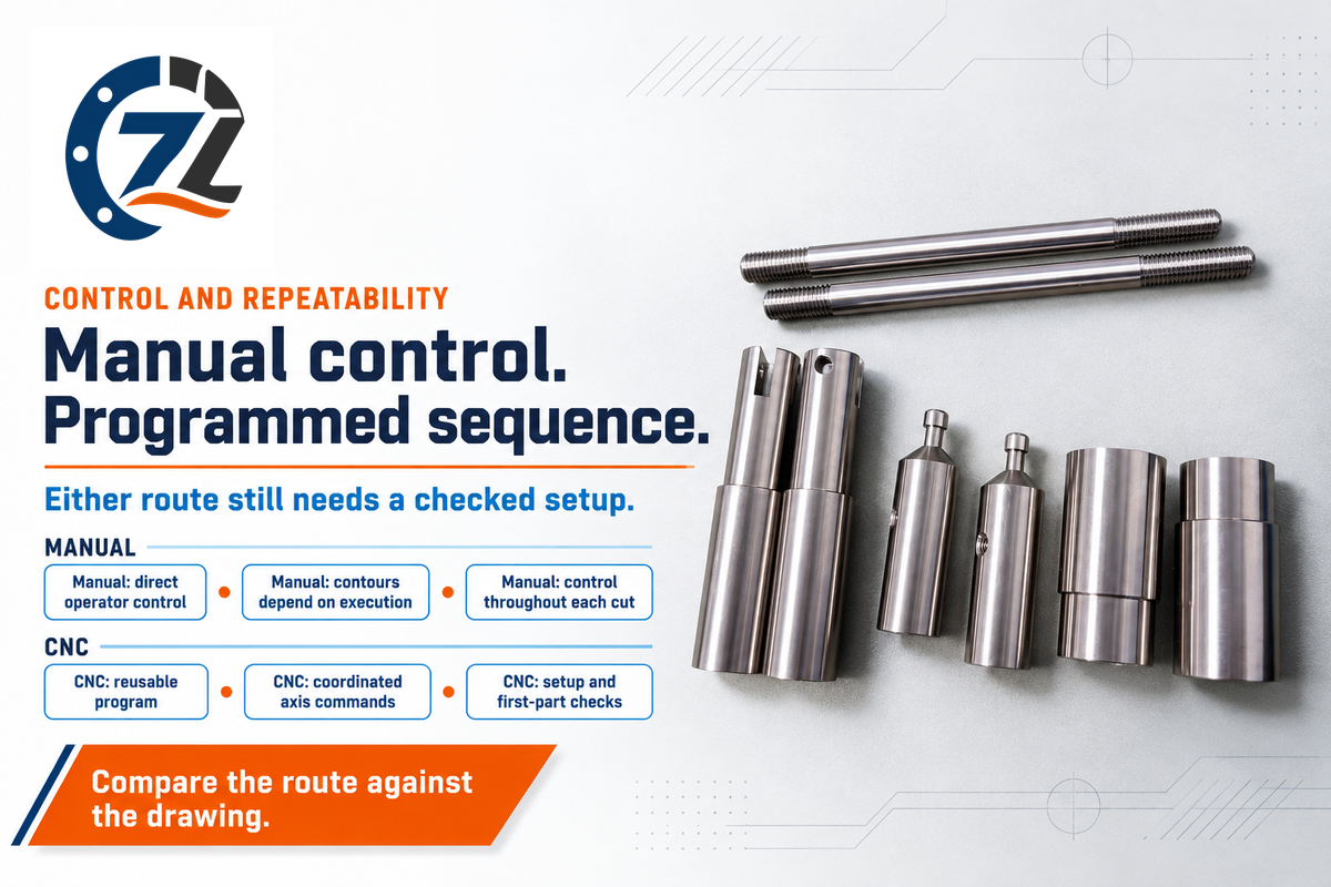
Computer control is useful if a route requires repeatable contours, coordinated axis movements or a program that can be reused. The National University of Singapore describes its two-axis CNC lathe as equipment for one-offs and small batches. Manual turning can manage an accessible repair or the manufacture of a simple individual component.
What is CNC turning?
CNC turning uses computer numerical control to control tool path, feed, spindle behavior and the sequence of operations of a lathe. CNC machines reproduce the programmed movements for the workpiece. Tool offsets connect the programmed geometry to the tools used. As such, a precise program still requires setup and first-part measurement to get it right.
The University of Florida training resources outline three types of programming: handwritten code, conversational programming and computer-aided manufacturing. Handwritten CNC code is still programmed control; it isn’t manual machining. Programming simple lines and arcs can be easy; complex shapes, however, often benefit from a 3D model and toolpath generation.
Manual route
- Direct operator control suits accessible adjustments.
- Repeated contours depend more on operator execution.
- Allow for operator control throughout each cut.
CNC route
- A reusable program controls the planned sequence.
- Repeated contours follow coordinated axis commands.
- Include programming, setup and first-part checks.
For a prototype that will return as a repeat order, retaining a checked program and setup record can be an advantage. Specify the high precision requirement and its method of inspection on the drawing, including for CNC machining.
Turning tools and material choices
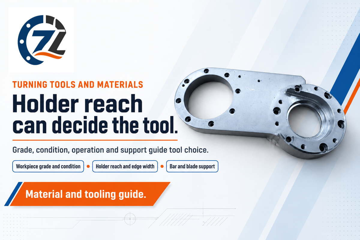
Of the many available options, select turning tools by workpiece material grade and condition, then narrow the choice by the intended operations and the available tool and workpiece support. Carbide inserts, high-speed steel, ceramic and cubic boron nitride tools have specific applications. A sharp edge with positive rake cuts differently from a stronger edge intended for interrupted or heavy cutting.
When a material is described as “steel,” many characteristics are left unspecified. Machining low-carbon steel can cause built-up edge and chip-control problems. Austenitic stainless steel presents different challenges compared to brass or aluminum. Hard turning of steel hardened to around 55-65 HRC requires different tooling from machining the same steel before hardening.
Nose radius influences tool choice based on profile and forces. A larger radius can reduce geometric feed marks, but it also changes contact and radial loading. For a flexible workpiece or a slender boring bar, increased forces can lead to chatter. Start within the insert supplier’s material and operation range, then select the edge geometry to match the stock left for finishing.
ISO 3685:1993 describes tool-life testing for high-speed-steel, cemented-carbide and ceramic single-point tools used on steel and cast iron. Compare tool life using stated cutting conditions and a wear criterion. A comparison of two inserts is useful only when the workpiece and test conditions are comparable.
For a grooved component, reach and edge width may decide the choice of holder before the cutting material does. Parting tools need adequate blade support, and an internal threading cutter must clear the bore. Mechanical constraints must be incorporated into the tooling plan before cutting speeds are selected.
Planning a turning setup
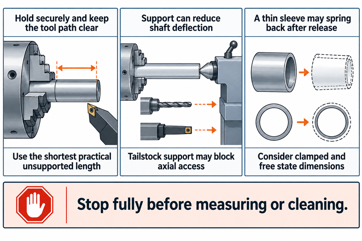
The setup for turning must hold the part securely so that the surfaces to be machined in that setup are accessible and the tool path is clear. The shortest practical unsupported length generally gives a stiffer arrangement. Deflection can be reduced by supporting a long shaft. However, a tailstock at the end may block an axial drill or boring bar.
Identify drawing datums, indicate which surfaces are gripped, and plan how the part will be transferred between setups. A thin sleeve can change shape under clamping force and spring back after release. Therefore, consider free state dimensions and those measured with clamping. For deep bores, check bar diameter, overhang and clamp support, if chatter occurs.
These concepts are elaborated in our turned parts workholding options. Mount the blank with enough usable stock for planned gripping and finishing surfaces; excessively long stock outside the chuck increases the unsupported span without helping the cut.
“If you need to measure or clean the workpiece, stop the machine and wait for it to come to a full stop.”
Include guarding and secure clamping of tools and workpieces in the setup. Remove the chuck key before operation. With the machine ready, perform a simulation to review tool path and check clearances. A controlled trial is done before production. Our article on verifying a CNC program covers this review in detail. When a program is altered, review the movements affected, especially those near the chuck and adjacent tools.
Turning speed, feed and cutting time
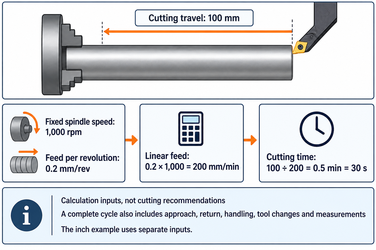
At a fixed 1,000 rpm and a feed of 0.2 mm per revolution, a tool takes 30 seconds to travel through a 100 mm cut. Cutting distance is divided by the linear feed to determine time. The selection of speed and feed for a material is different from calculating the time those inputs produce.
Keep spindle speed and cutting speed distinct. The term spindle speed, n, represents the speed in revolutions per minute. Cutting speed, Vc, is the surface distance passing the edge per minute. With diameter D in millimeters, Vc = π × D × n ÷ 1,000, in m/min. A 50 mm diameter rotating at 700 rpm gives approximately 110 m/min. Rearranging gives n = 1,000 × Vc ÷ (π × D); 110 m/min at 50 mm gives approximately 700 rpm.
3-Step Turning Time Check
- State the travel and operating mode. Use 100 mm of cutting travel at a constant 1,000 rpm.
- Convert feed per revolution to linear feed. At 0.2 mm/rev, linear feed F = 0.2 × 1,000 = 200 mm/min.
- Divide travel by linear feed. Cutting time t = 100 ÷ 200 = 0.5 min, or 30 seconds.
| Input or result | Value |
|---|---|
| Cutting travel | 4 in |
| Spindle speed | 1,000 rpm |
| Feed per revolution | 0.008 in/rev |
| Linear feed | 0.008 × 1,000 = 8 in/min |
| Cutting time | 4 ÷ 8 = 0.5 min = 30 s |
The inch inputs are a second example, not conversions of the metric inputs. For surface speed in feet per minute, use Vc = π × D × n ÷ 12 with D in inches. At 2 in diameter and 700 rpm, this gives about 366.5 ft/min. Our speed and feed calculator provides a separate place to work through parameters.
Radial depth of cut is half the diameter reduction. Example: reducing a cylindrical diameter from 50 mm to 46 mm removes 2 mm radially, because (50 − 46) ÷ 2 = 2 mm. Treating the 4 mm diameter change as radial depth would double the intended cut.
Cutting Tool Engineering’s explanation of facing time distinguishes constant spindle speed from constant surface speed. With constant surface speed, rpm varies with changes in the cutting diameter and can reach a programmed ceiling. The above fixed rpm time calculation applies to its stated mode; a complete production cycle includes approach, return, handling, tool changes and measurements.
Turning tolerances and surface finish
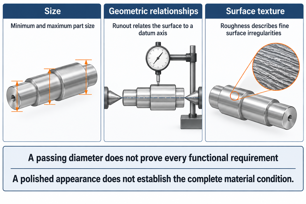
After turning a part, it must be checked separately for size, geometric relationships and surface texture. Tolerances affect the minimum and maximum size of the part. Roughness of a surface describes its fine surface irregularities. Runout, on the other hand, relates to the surface of the part in relation to a datum axis. A diameter that passes inspection can still leave a rotating assembly or sealing surface that’s outside of its functional requirements.
Work on surface texture by NIST describes the effect of surface texture on friction, wear, lubrication, and sealing. For a bearing seat, both size and roundness are considerations. For a seal contact surface, texture also comes into consideration. The drawing should illustrate these constraints. The description of circular and total runout differentiates two geometric checks that are often confused.
Chatter marks on a part indicate a dynamic issue with tool cutting. Check workpiece support, tool overhang and holder rigidity before assuming feed is the only cause. A long shaving wrapped around a part suggests a different issue: the chip may not be reaching the insert’s chipbreaker in the intended way. Production Machining explains that cutting with a low feed may encourage built-up edge and that excessive feed may increase pressure on the cutting edge.
An appearance of polish doesn’t always reflect the complete truth about the material condition. A 2024 study of 42CrMo4+QT steel evaluated roughness and residual stress using confocal microscopy and X-ray diffraction. For parts whose design necessitates control of surface integrity, keep those requirements distinct from a roughness value. The extent of dimensional inspection and material evaluation is determined by the applicable drawing and acceptance plan.
What affects the cost of turned parts

The cost of a turned part includes both non-recurring and recurring costs. Programming and setup are non-recurring activities whose costs are distributed over the batch. Stock, cutting, handling and inspection contribute to recurring production costs. Tightening the tolerance or adding a feature on the rear face of a part can alter the route and change the costs even if the outer diameter of the part doesn’t change.
The NIST manufacturing-cost framework breaks time into operating, setup and non-operating time. It also spreads the cost of dedicated tooling, such as jigs, over the production quantity. These distinctions allow procurement to compare quotations more effectively than by simply multiplying the duration of one cutting pass by an hourly rate.
A per-part price requires a defined drawing, material, quantity and inspection scope. The first estimate of unit cost would be fixed preparation cost ÷ quantity + material per part + time per part × shop rate + other recurring costs per part. Time is in hours for rates that are per hour. The setup charge, material allowance, complete cycle time, hourly rate, and per part finishing and inspection cost should be from the same supplier. This estimates manufacturing cost; a selling quotation may also include margin, packing, freight and tax. The cost of a 30 second cutting pass, by itself, isn’t sufficient to determine delivered price.
Turned-Part Cost Breakdown
| Cost item | What drives it | Comparison point |
|---|---|---|
| Raw material | Grade, condition and starting stock size | Use the same material specification. |
| Programming | Contour and operation sequence | Separate initial preparation from repeat-order use. |
| Workholding setup | Locating surfaces and required fixtures | Identify any dedicated jaws or fixture charge. |
| Cutting | Travel, feed, passes and tool path | Include all operations, not only outside turning. |
| Loading and transfer | Part handling and setup changes | Include rear-face or second-operation access. |
| Tool consumption | Wear, breakage and usable edges | Keep consumable inserts separate from dedicated fixtures. |
| Inspection | Required characteristics and measurement scope | Use the same acceptance requirements. |
| Secondary work | Milling, deburring or specified treatment | Identify work included in the delivered condition. |
| Quality losses | Scrap and rework | Compare cost per acceptable delivered part. |
Example: the same setup charge spread over 100 parts contributes one tenth as much per part as it does over 10 parts. The other costs are still there. A repeat order may reuse preparation that a new design cannot. For a buyer comparing prototype and production quotes, separating the fixed charge makes the difference understandable without assuming that every element of the piece price falls by the same ratio.
Tool usage has its own tradeoff. In a 2024 turning-cost study, four parts per insert gave a lower cost objective than three or five under the tested conditions. Extending an insert’s use can raise wear-related costs; replacing it too early can waste usable cutting life.
Zhenling Metal uses CNC lathes for drawing-based elements such as rolls, flanges, valve bodies and plugs. Provide the full drawing, the material condition, quantity and surface requirements for a part requiring CNC turning and milling. For additional information on our available production routes, please consult our machining processes page.
What is changing in turning automation
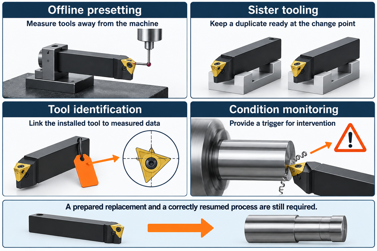
Automatic tool management aims to reduce the time lost to preparing, finding, measuring and replacing tools. It’s most effective in environments where those tasks repeatedly interrupt production. Increasing spindle speed won’t remove a wait for an unavailable replacement insert, and a bigger tool store won’t correct an unstable cut or a recurring chip control problem.
An IMTS article published in August 2025 for the 2026 exhibition mentions offline presetting, sister tooling, and tool identification and condition monitoring. Offline presetting takes tool measurement out of the machine. Sister tooling maintains a duplicate ready when the active tool reaches its change point. Identification systems link the installed tool to its measured data.
The functions solve different issues. A shop that stops because a tool insert wears out benefits from different adjustments than a shop that stops because of tool touch-off. Tool monitoring can provide a trigger for intervention; the response still needs a prepared replacement and a process that resumes correctly. The turning machine’s holder interface, offsets and tool-clearance arrangement must suit the proposed system.
For a new production flow, offline presetting may reduce on-machine tool measurement. Sister tooling keeps a duplicate tool preset and ready for use. Evaluating a supplier’s cycle time improvement may be easier if the task that’s no longer performed (cutting, measuring, loading, etc.) is identified. The handling and checking work left to be performed may be as important as what’s removed. For repeat orders, a consistent program, tool list and setup record make the expected route easier to reproduce.
Frequently asked questions
What are the different cutting tools for lathes?
Lathe cutting tools include external turning and facing tools, boring bars, grooving tools, threading tools and parting tools. Drills and reamers perform related hole-making operations. The holder provides reach and support; the cutting edge determines the usable geometry and material range. A single tool can sometimes perform several moves, but a narrow groove or internal thread often needs a dedicated tool.
What are the similarities between milling and turning?
Milling and turning both remove material along a controlled tool path to make a part from stock. Both require suitable tools, secure workholding and inspection against the drawing. Their main difference is cutting rotation: a conventional turning process rotates the workpiece, while a mill rotates the cutter. A part can require both processes when it combines round surfaces with slots, flats or cross-holes.
What is CNC milling?
CNC milling uses a rotating cutting tool and programmed movements to remove material from a secured workpiece. Milling machines make features such as pockets, flats and off-axis holes. Some CNC lathes add driven tools and extra axes for these operations. A combined machine can reduce transfers, but its working envelope and tool access still have to cover the part’s features.
What are the downsides of CNC turning?
CNC turning requires programming and setup before the first acceptable part, and conventional turning mainly produces axisymmetric surfaces. Off-axis features need additional capability or operations. Tool wear, poor clamping and wrong offsets can also affect a whole run if the process isn’t checked.
Why can a lighter finishing cut make chip control worse?
A very shallow cut or very low feed can keep the chip from engaging the insert’s chipbreaker properly. The edge may rub or develop built-up material instead of producing the intended chip. Reducing feed can make the theoretical feed marks smaller while making the cutting action less stable.
Separate feed per revolution from radial depth when diagnosing the problem. Inspect the edge, material condition and support, then compare the remaining stock with the insert’s finishing range. A roughing geometry may be unsuitable for the available finishing allowance. Switching to an appropriate finishing edge can be more useful than repeatedly shaving away smaller amounts. If chatter is present, include bar overhang and clamping in the diagnosis; increasing feed without addressing flexibility can create a different problem.
Plan the whole turned component. Include the surfaces made after the first setup, the required material condition and the inspection criteria in the drawing package. Zhenling Metal can review the route for your drawing-based metal parts and prepare a quotation against that scope.
References & Sources
- Turning University of Arkansas, Introduction to Mechanical Design and Manufacturing.
- Lathe Toolpath Guide Purdue University.
- Training Workshop National University of Singapore.
- CNC Lathe Training Resources University of Florida.
- ISO 3685:1993, Tool-life testing with single-point turning tools International Organization for Standardization.
- Metalworking Lathe Safety Awareness Guide Cornell University.
- Cutting Time for Facing Cutting Tool Engineering, Edmund Isakov.
- Surface Texture and Forensic Topography National Institute of Standards and Technology.
- 4 Strategies for Managing Chip Control Production Machining, edited by Chris Felix.
- Turning of 42CrMo4+QT under different scenarios Díaz-Salamanca and colleagues, 2024.
- Design-for-Cost: An Approach for Distributed Manufacturing Cost Estimation National Institute of Standards and Technology.
- Turning-parameter optimization for tool sustainability and machining economics Chung, Andrianto and Wang, 2024.
- 10 Tool Change and Management Automation Solutions at IMTS 2026 IMTS.