Circular Runout vs Total Runout: What Each Control Covers


Circular runout checks individual circular elements. Total runout assesses the indicated surface as a whole against a datum axis. The practical difference in runout vs total runout is whether sections can pass as the surface changes along its length. Both controls are by rotation. The drawing determines the controlled surface, tolerance and datum relationship.
Updated October 2026
Quick Specs
- Circular: evaluate each applicable circular element over a complete revolution.
- Total: evaluate the specified surface with one common datum relationship.
- Radial inspection: probe toward the axis; face inspection: probe parallel to it.
- Actual feature size: retain its separate dimensional requirement.
Circular and total runout at a glance
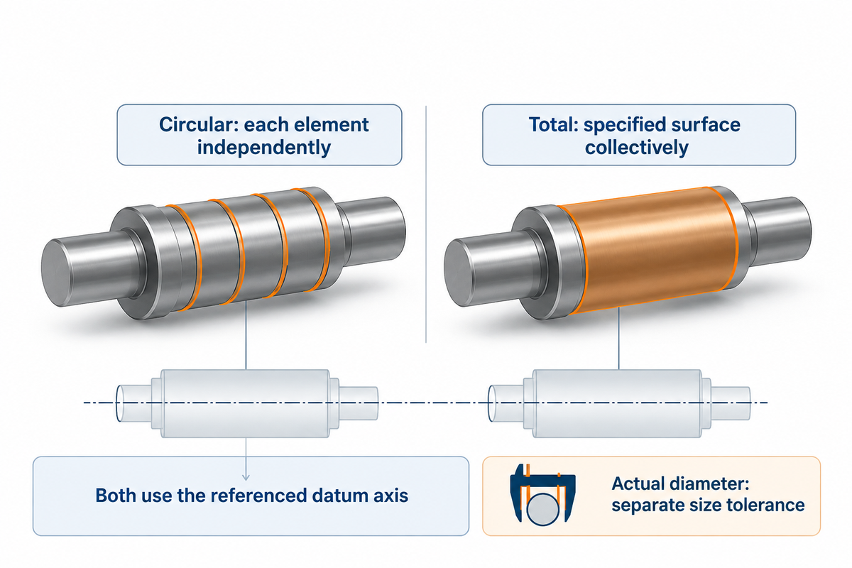
Circular and total runout differ in the extent of the surface evaluated as a whole. Let’s assume we’re checking separate rings on a shaft, then the sleeve those rings occupy. A circular check accepts each ring independently. A total requirement also limits the relationship of those rings along the indicated surface.
The runout chapter of James D. Meadows’ ASME Press handbook distinguishes indicator movement at circular cross-sections from movement while traversing the entire surface. Read the control frame with its surface attachment; the same numerical tolerance has a different reach under the two symbols. Our drawing-led inspection guide explains how to connect a requirement to its inspection record.
| Decision | Circular runout | Total runout |
|---|---|---|
| Evaluation extent | Each circular element independently | Specified surface collectively |
| Radial zone | Two concentric circles at each section | Two coaxial cylinders across the surface |
| Planar face zone | Two circles in parallel planes at each radius | Two parallel planes across the face |
| Datum relationship | Referenced datum axis | Referenced datum axis |
| Indicator path | One circular path at a time | Rotation plus coverage across the surface |
| Separate section offsets | Not combined into one longitudinal requirement | Included in the common surface evaluation |
| Taper along a cylinder | Can escape independent local ranges | Consumes the shared radial zone |
| Actual diameter | Separate size tolerance remains | Separate size tolerance remains |
| Assumed 0.020 mm limit | Applies to each local range | Applies to the collective range |
| Inspection record | Identify checked sections or radii | Identify surface coverage and common reference |
A designer choosing between runout or total runout should identify where the mating component makes contact with the part. A long sealing surface and a narrow contact band can demand a different control extent. Specifying a broader control everywhere can add inspection work without improving an unrelated function.
Circular runout evaluates each circular element
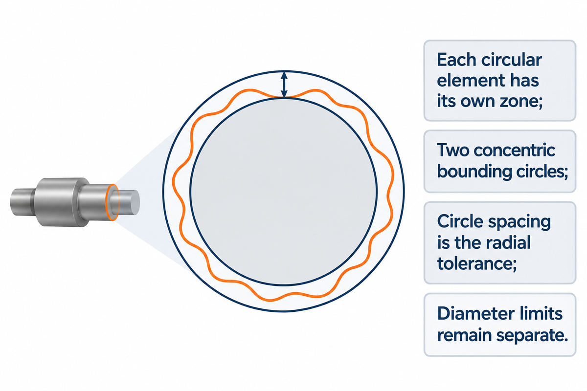
Circular runout on a shaft limits each circular element as the part turns around the datum axis specified on the drawing. For a cylindrical surface, a cross-section has its own pair of concentric bounding circles. The distance between those circles is the radial tolerance, not the diameter of a cylindrical tolerance zone.
Circular cross-sections are treated independently in Meadows’ handbook chapter. A public geometric-tolerance guide by Mitutoyo illustrates the same circle-based geometry. Therefore, a local ring can be circular about the datum while the radius changes along the shaft. This is why a single good runout value at the accessible end may not resolve a longitudinal taper.
What is a runout in GD&T?
In GD&T, runout refers to a geometric tolerance relating an indicated surface to a datum axis through rotational movement. GD&T is geometric dimensioning and tolerancing. A single-arrow runout symbol defines circular runout; a double-arrow total runout symbol defines a collective surface control. The feature control frame also defines the tolerance and datum references.
- Read which surface the leader identifies.
- Establish the referenced datum axis before rotating the workpiece.
- Check the entire circular element at each required inspection location.
- Retain the diameter limits shown elsewhere on the drawing.
Circular runout can limit variation at the contact band of a sleeve whose seal rotates against that band. If the seal moves axially across a long cylindrical land, isolated ring checks leave gaps in the functional question, and the designer needs to address that travel length explicitly, instead of adjusting the local callout. An inspector should mark the section locations for comparison with the original inspection. A purchasing team evaluating quotations should agree on that extent in the inspection; otherwise, a report that captures one convenient reading can look the same as a report that covers all working land.
Total runout uses a collective surface requirement
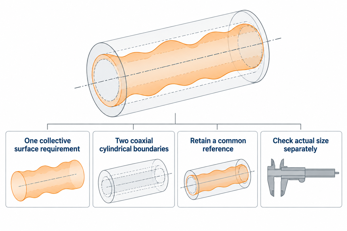
Total runout restricts the specified surface in its entirety relative to a datum axis. For a cylinder, that surface has to be between two coaxial cylinders that are spaced radially by the stated total runout tolerance. Thus, longitudinal surface variation consumes the same allowance as circumferential variation. Setting separate sections to zero and reporting only local ranges loses that common-reference evaluation.
The distinction between section measurements and traversing the surface appears in the ASME Press runout chapter. Total runout provides overall form control relative to a datum, including longitudinal departures that independent circular checks can miss. Surface attachment and the indicated extent determine which area comes under evaluation.
Advantages of total runout
- Combines circumferential and longitudinal surface variation.
- Relates the controlled surface to the specified axis.
- Addresses a continuous working land rather than isolated rings.
Limitations to plan around
- Requires coverage across the indicated surface.
- Needs a stable common reference during evaluation.
- Leaves actual size and other drawing requirements to their own checks.
Constant diameter cylinders can be too large and have a small total runout. Likewise, a diameter can pass at one station while overall form fails because the radius changes along the shaft. Keep size and geometry as separate report characteristics. Our dimensional tolerance guide explains how to deal with these requirements on the same drawing.
The 3-Station Taper Test
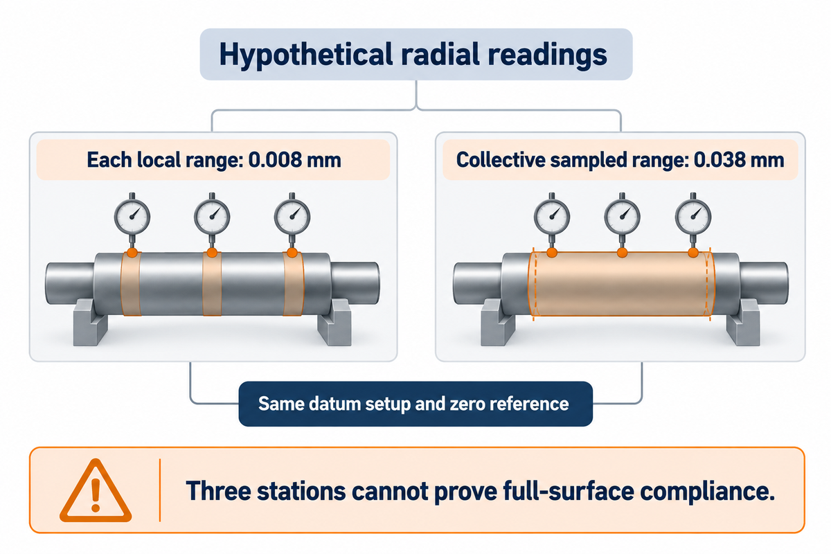
The 3-Station Taper Test is used to compare local indicator ranges to a shared range to uncover a taper hidden by separate ring checks. The same datum setup and zero reference are used for the comparison. The minimum is subtracted from the maximum at each station, then across all sampled stations. Longitudinal offsets that disappear during local evaluation are uncovered by this test.
Assumed inputs: the following hypothetical radial indicator readings use one fixed datum axis, one unchanged zero reference and comparable probe direction. Each station is assumed to be a full revolution. The assumed limit is 0.020 mm. The readings illustrate arithmetic; they aren’t measurements from a Zhenling Metal production part.
| Axial station | Minimum | Maximum | Local range |
|---|---|---|---|
| 0 mm | 0.000 mm | 0.008 mm | 0.008 mm |
| 40 mm | 0.015 mm | 0.023 mm | 0.008 mm |
| 80 mm | 0.030 mm | 0.038 mm | 0.008 mm |
At the middle station, the local range is 0.023 – 0.015 = 0.008 mm. The collected, sampled range is 0.038 – 0.000 = 0.038 mm. All three local ranges are less than the assumed limit, while the collective sampled range exceeds the limit. A change is uncovered by the shared reference that local subtraction removes.
Under the ideal measurement assumptions, the sampled collective excursion has already exceeded limits. Three axial stations can’t show compliance of the entire surface, as unexposed areas may contain larger variations. Actual acceptance requires a suitable datum setup, and the agreed upon measurement decision rule. As discussed by Meadows, the example shows a distinction between sections and surfaces; it doesn’t provide a means of calculating actual shaft diameter, given an indicator offset.
Engineering Note
For this assumed 0.020 mm requirement, don’t subtract a new local zero at each 40 mm step when assessing the collective range. Preserve the reference in the raw record. A full-surface inspection plan must also cover the space between the demonstrated stations.
Establish the datum axis before reading the indicator
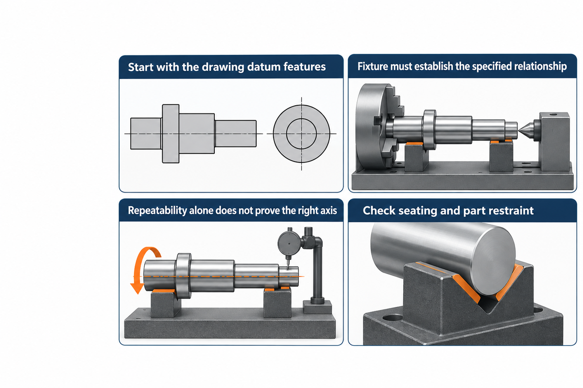
The datum axis comes from the drawing’s referenced datum features and their required establishment. A machine spindle, chuck or pair of center holes is a reference only when the setup establishes the specified datum relationship. A repeatable but incorrect setup can produce readings about the wrong reference, and fixture selection comes before comparison with the runout tolerance.
In Form 101, Patrick Nugent explains why convenient machining references and functional datum references can differ. A centering fixture must represent the specified relationship, rather than merely make the needle move less. ISO 5459:2024 separately defines the GPS datum specification operator; its public scope does not prescribe a universal physical verification fixture.
Does runout control location?
Partly: runout controls the surface relationship to its datum axis, but it isn’t a substitute for every feature location requirement. Hole-pattern position, mating dimensions, and other independent requirements still need their specified controls. Compare actual function before replacing GD&T symbols.
Suppose a drawing references a finished bearing journal, but the inspector rotates the shaft between manufacturing centers. The finished journal can be displaced from those centers. An indicator then couples that setup relationship with the variation of the surface being checked. Repeating the reading doesn’t correct the reference. For consistent runout measurements, the quality engineer must identify how the finished datum feature is simulated and check seating repeatability before accepting the result. For a procurement team, the important question is which drawing datum the quoted inspection establishes. A photo of a part between centers addresses the fixture question only if those centers establish the specified relationship.
- Identify the datum feature or features and their order.
- Check seating, contamination and part restraint.
- Document the axis-establishment method in the inspection instruction.
- Repeat the setup when investigating unstable results.
Radial and axial runout need different probe directions
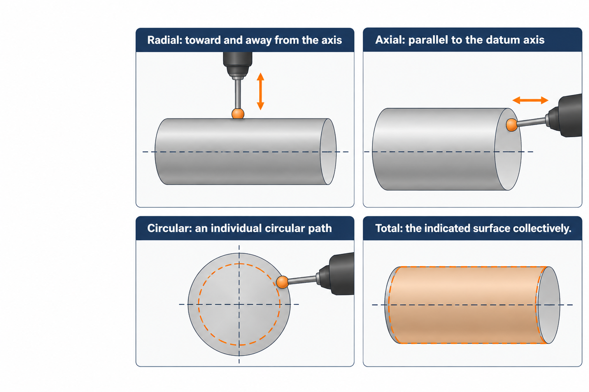
In circular runout measurement, radial runout measures motion towards and away from the datum axis. Axial runout measures motion that’s parallel to the datum axis, which is usually the case with the end face of a rotating part. Circular axial inspection is with respect to a ring at a selected radius, and total axial inspection is with respect to the face as a whole. For the measurement of face wobble, both probe direction and surface coverage must be changed simultaneously.
In the handbook’s discussion on planar surfaces, runout of a face is treated differently from runout of a cylinder. In Mitutoyo’s tolerance diagrams, a circular face zone consists of circles between parallel planes, and the total face zone spans parallel planes across the face. Applying a radial measurement procedure to a face without changing the probe direction may leave face wobble unexamined.
| Surface and control | Probe direction | Coverage |
|---|---|---|
| Cylinder, circular | Radial | Individual circular cross-section |
| Cylinder, total | Radial | Indicated cylindrical surface collectively |
| Face, circular | Parallel to axis | Individual circular path at a radius |
| Face, total | Parallel to axis | Indicated face collectively |
A thrust face relates to the rotation axis. Flatness concerns face form alone. Perpendicularity relates face orientation to a datum under its own zone rules. The difference comes up when a flange evenly seats on a plate but wobbles in rotation. For the datum-free form question, see our line and whole face control comparison.
Measure runout without losing the common reference
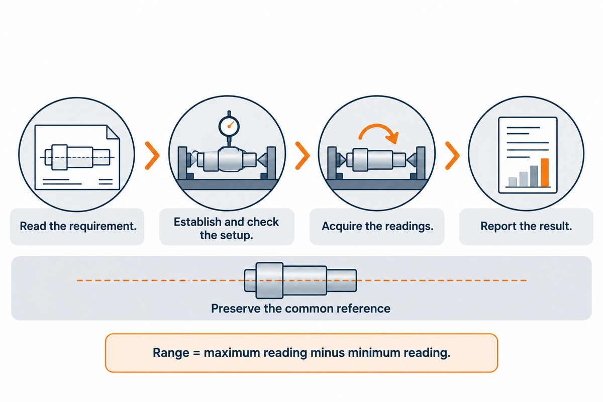
To measure runout, establish the specified axis, align the indicator in the required direction, rotate the part through a complete revolution and retain extreme readings. Measuring total runout requires the indicated surface to be covered with a common reference. When using a dial indicator, a reset between locations can remove the longitudinal variation that the inspection needs to capture.
The NIST discussion of single-trace roundness measurement states that a trace consists of both workpiece error and spindle error. These two components can’t be isolated from the trace alone. Spindle error can be ignored when it is sufficiently small and within known limits, except for the most precise measurements. The proper approach is to evaluate the measurement system to decide if it’s suited to achieve the tolerance.
- Read the requirement. Identify surface, extent, datum references and the complete specification.
- Establish and check the setup. Seat the datum features and check measurement-system repeatability.
- Acquire the readings. Spin the part through each required path under controlled rotation; preserve the reference for the collective evaluation.
- Report the result. Retain extremes, coverage, setup and the decision rule used for acceptance.
Is TIR the same as runout?
Not exactly: TIR is an indicator range, also called total indicator reading or total indicated runout. The name alone doesn’t identify circular runout or total runout drawing control. Specify where the probe has moved and the datum axis that was used. Maximum reading minus minimum reading gives the indicated range, including when one reading is negative.
“TIR is not a substitute for roundness and there is no conversion factor between the two.”
Sampling also impacts what an inspection can find. NISTIR 5698 studies how point distribution affects uncertainty in small circular features measured on coordinate measuring machines. A CMM can give three-dimensional coordinates, but its alignment, point distribution and evaluation should match the characteristic. An automated result heading can’t establish coverage by itself.
Near a limit, apply the agreed uncertainty decision rule. ISO 14253-1:2017 addresses conformity decisions under its GPS scope. It does not automatically become the contractual rule on every ASME drawing. Our measurement uncertainty discussion shows why a rounded pass/fail value can hide a borderline decision.
Choose a control around function and inspection effort
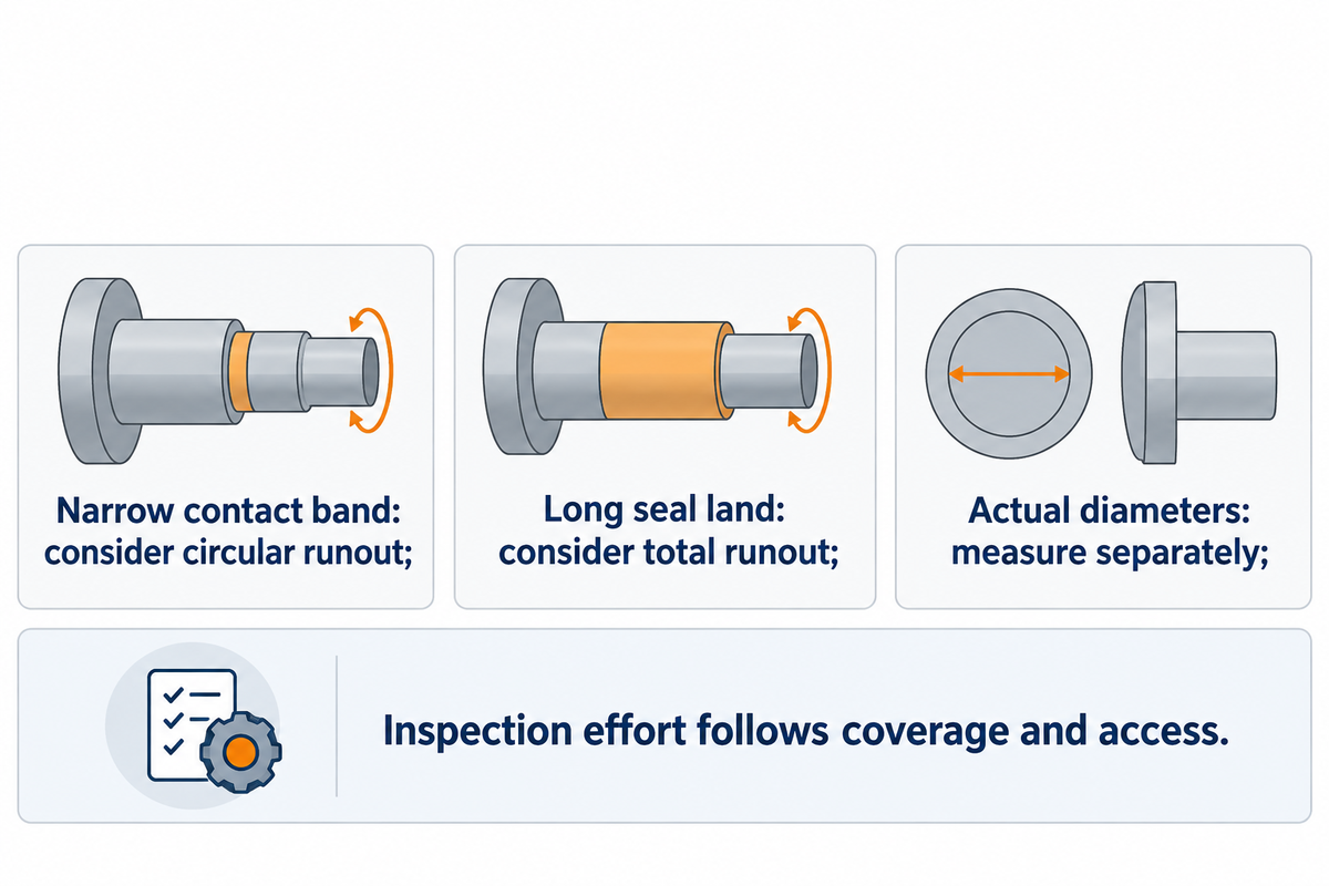
Choose circular runout when you need to keep individual circular elements within their datum-related limits. Total runout comes into play when longitudinal surface variation also matters across the working area. The effort required for inspection follows the coverage, access, and datum set up. A broader control doesn’t always mean a universal price multiplier or inspection-time ratio.
The distinction between section and surface in Meadows’ runout chapter provides the bases for the following conditional decisions. View them as design decisions, not as ironclad substitutions for an existing drawing. Another option is provided in our surface profile guide when the function is related to a more general surface form.
| Feature type or application | Control to consider | Reason and inspection consequence |
|---|---|---|
| Narrow rotating contact band | Circular runout | Check datum-related variation at the functional band |
| Long sliding seal land | Total runout | Evaluate the working length collectively |
| Journal with suspected taper | Total runout plus size checks | Retain section offsets and measure actual diameters |
| Thrust face around a fixed contact radius | Circular axial runout | Evaluate the ring in the axial direction |
| Broad rotating flange face | Total axial runout | Cover the indicated face with one common reference |
| Free-standing cylinder form only | Cylindricity | Assess cylinder form without importing a datum relationship |
| One circular section form only | Circularity | Evaluate roundness independently of a datum |
| Nonrotating face seating | Flatness and any needed orientation control | Separate face form from its assembly relationship |
| Bore in a bushing relative to its outside journal | Datum-related runout if function requires it | Plan internal access and datum simulation together |
| Legacy concentricity requirement | Engineering review before substitution | Identify the original standard and functional intent |
For long sleeve orders, some suppliers may quote local runout checks at accessible ends, while others include a traverse of the working land. Coverage statements must be compared. For total runout, the first inspection scope must be revised, even if its indicator has smaller resolution. A dedicated, repeatable fixture may be used to evaluate a feature in high-volume applications. Whether or not it’s used, access and datum simulation still determine whether it evaluates the required feature. An intermediate check of runout during manufacturing may identify process movement, but final acceptance must address the finished drawing requirement. No process saving is achieved from simply renaming the control.
Drawing and inspection handoff before a machining quote

Design teams should specify runout with the drawing revisions, controlled surfaces, symbols, and references to tolerance and datum with their machining quotes. Include surface coverage and reporting requirements. These fields allow designers, machinists, quality engineers, and procurement to understand the same job before production starts, rather than reconcile different interpretations after inspection.
The American Society of Mechanical Engineers currently lists ASME Y14.5-2018 (R2024); the parenthesized year records reaffirmation. Use the standard specified on the drawing. The International Organization for Standardization publishes a separate GPS framework, so the practical differences in our ASME and ISO drawing guide belong in the drawing review.
- Design: identify the functional land or face and retain the separate size limits.
- Machining: state the datum features available at the inspection stage and any access restrictions.
- Quality: define paths, surface coverage, reference preservation and the reported characteristic.
- Procurement: include report format, required quantity of inspected parts and any agreed uncertainty decision rule.
Provide the marked drawing when requesting CNC machining services and a runout check. A note that says “check runout” doesn’t define the extent of runout being checked or the reference. A usable spec identifies the surface and repeats the original frame in the inspection instruction; it isn’t intended to remove the drawing and replace it with an informal indication. The Metrology Hub elaborates on these checks and their relation to the overall inspection plan.
Preparing a precision manufacturing inquiry? Send the drawing revision, datum scheme and required runout report through Zhenling Metal’s machining website. Include whether the controlled surface needs local circular checks or a collective surface evaluation.
Frequently asked questions
Does total runout control shaft diameter?
No. Total runout limits surface variation relative to a datum axis; the actual diameter remains subject to the size tolerance.
A cylinder with a consistent radius can produce little indicator movement even when its diameter is outside the permitted limits. Measure size separately with a method appropriate to the dimensional specification. Conversely, diameters that pass at selected sections can still hide a taper that fails total runout. Record both characteristics when the drawing specifies both, so the acceptance report addresses size as well as geometric variation.
Can tighter circular runout replace total runout?
No. Tighter circular runout leaves longitudinal offsets uncombined, so a taper can pass every ring check and still fail total runout.
Reducing each local range can improve the circular elements while a taper or other longitudinal departure remains. Substitution requires a design decision about the functional surface, followed by an authorized drawing change. An inspector cannot make that substitution merely because one method is easier to perform. Preserve the original control until the drawing owner has approved the alternative and its acceptance method.
Can total runout replace cylindricity?
Not as a direct swap: total runout adds a datum relationship, while cylindricity controls cylinder form alone.
A cylinder can have acceptable form while its axis is displaced or tilted relative to a separate datum. Adding a datum relationship can therefore reject a part that meets a form-only requirement. Replacing one control with the other changes the acceptance question. Review the mating function and drawing requirements before making the change, and document which characteristic the inspection report actually evaluates.
Can a datum feature have a runout requirement?
Yes. A feature used to establish a datum can also have its own runout or other geometric requirement relative to another datum.
Interpret each control frame separately. The datum label identifies a reference role; it does not erase other requirements on that feature or approve a particular fixture.
Does a negative indicator reading automatically fail?
No. A negative indicator reading alone does not fail a runout check; the range is the maximum minus the minimum.
Keep the sign in the raw readings. Compare the resulting range with the applicable limit using the specified setup and acceptance rule.
Related Articles
References & Sources
- Runout, chapter 9, Geometric Dimensioning and Tolerancing Handbook James D. Meadows, ASME Press, 2009; public chapter abstract.
- Form 101 Patrick Nugent, Quality Magazine, 2015.
- ISO 5459:2024, Datums and datum systems International Organization for Standardization; public scope.
- Single-trace roundness measurement National Institute of Standards and Technology, Engineering Statistics Handbook.
- NISTIR 5698, Estimation of measurement uncertainty in small circular features measured by coordinate measuring machines National Institute of Standards and Technology, 1995.
- ISO 14253-1:2017, Decision rules for verifying conformity or nonconformity with specifications International Organization for Standardization; public scope.
- ASME Y14.5-2018 (R2024), Dimensioning and Tolerancing American Society of Mechanical Engineers; edition and reaffirmation record.
ABOUT ZHENLING
Custom machining from drawings and samples
Shanghai Zhenling Hardware Co., Ltd. was established in 2006. Its Jiashan, Zhejiang factory covers an 8,000 m² site with a 6,000 m² workshop for custom machined metal parts.
The team works from drawings and samples for applications including pressure vessels, oil-gas separation, and fluid control. Material experience includes carbon, alloy, and stainless steels as well as special alloys.
- 3-, 4-, and 5-axis CNC machining
- Grinding, wire cutting, and welding
- Domestic and export divisions
CONTACT PROFILE
Company details
- NAME
- Shanghai Zhenling Hardware Co., Ltd.
- ESTABLISHED
- 2006
- LOCATION
- Jiashan, Zhejiang, China
- FOCUS
- Custom machined metal parts from drawings and samples
- CAPABILITIES
- 3/4/5-axis CNC machining, grinding, wire cutting, and welding
- CONTACT
- Share the drawing, material, quantity, and critical requirements.