Updated October 2026
Quick Specs
- Workpiece: electrically conductive material.
- Removal mechanism: controlled sparks across a dielectric-filled gap.
- Common routes: sinker cavities, wire-cut through-profiles and drilled holes.
- Acceptance: dimensional tolerance, surface texture and metallurgical condition are separate requirements.
Electrical discharge machining removes conductive material with controlled sparks across a fluid-filled gap. It can form deep cavities and fine details without a cutting edge, but electrode wear, machining time and surface integrity still affect the finished part.
A mold insert with a deep narrow rib may warrant consideration of electrical discharge machining. Use EDM when the feature and acceptance conditions justify the added tooling and burn time. A wide, accessible pocket usually warrants a milling comparison first. The key question to ask is what feature requires EDM and what operations determine the readiness of that feature to ship.
Key points
- In published wire-EDM trials, smoother surfaces still carried higher tensile residual stress.
- Choose a process from feature access and acceptance requirements, not hardness alone.
- Separate initial tooling from recurring electrode consumption when comparing quotes.
- A machine positioning specification isn’t the tolerance of a delivered part.
How electrical discharge machining works
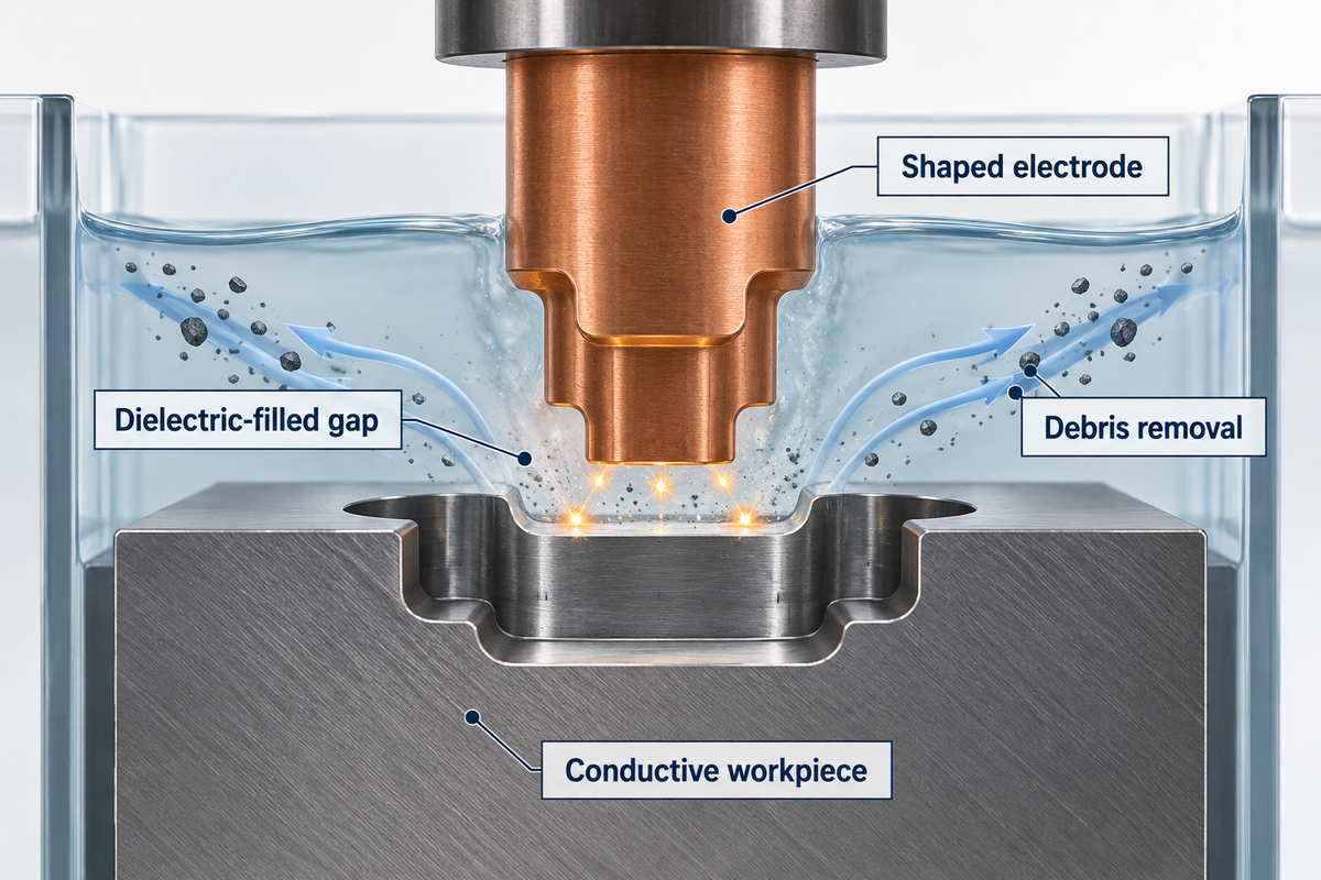
The electrical discharge machining process uses electrical sparks to erode material in a conductive workpiece. An electrode approaches the surface without functioning as a cutting edge. Controlled electrical discharges cross the small gap and erode the material, leaving debris that must be removed by the dielectric system before stable cutting can be resumed.
The University of Wisconsin, Milwaukee process description indicates that recurring sparks are observed between two electrodes separated by a dielectric liquid. The workpiece is one of the electrodes. In sinker EDM, the other is a shaped tool, the geometry of which defines the cavity obtained by using electrical discharges, and which undergoes controlled motion, rather than being forcibly pushed into the metal.
EDM machines use a power supply and gap control to regulate the electrical pulses. Together, these functions control the EDM process rather than allowing a continuous arc to burn uncontrolled. A spark discharge creates intense local heating; material melts and some vaporizes. In the interval between pulses, the gap must recover and debris is required to move away from the gap. Repeated small discharges under stable conditions are useful to melt the material. Continuous arcing in a contaminated gap is a different condition and can damage the surface.
Initially, the liquid dielectric fills the gap and insulates it. Later, as the electric field builds up and produces breakdown in the gap, it allows discharge. It also helps cool the machining zone and carry particles away. Electrical conductivity closes the electrical circuit, but electrical properties alone don’t set cutting speed. Geometry, flushing, and the selected discharge energies also influence machining performance.
The process is also known as spark machining. As a non-traditional machining technique, EDM doesn’t require an electrode that’s harder than the workpiece, as in conventional machining. Wear still alters the tool, so the controller and electrode strategy must account for it. Contactless, as in electric discharge machining, describes the removal mechanism; it doesn’t mean that the metallurgical surface of the workpiece remains unchanged.
EDM types: sinker, wire and hole drilling
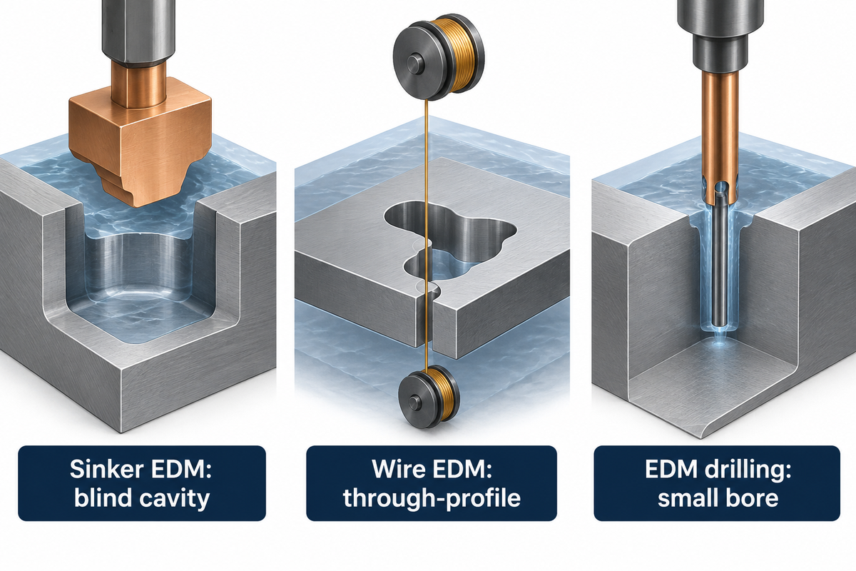
Choose the type of EDM based on the shape and access of the feature to be machined. Sinker EDM uses, in general, shaped electrodes for cavities and other intricate forms. Wire EDM produces through-profiles with a traveling wire. Hole drilling EDM uses a fine electrode to machine small bores.
| Route | Tool and feature | Planning question |
|---|---|---|
| Sinker or ram EDM | Shaped electrode; blind cavities, ribs and mold details | Can the tool enter, flush and withdraw without damaging the required form? |
| Wire EDM | Traveling wire; through outlines and slots | Is there an open edge or a suitable start-hole path? |
| Small hole EDM | Slender, commonly tubular electrode; bores and start holes | How will depth, breakthrough and the bore be checked? |
Wire EDM uses a continuously fed wire electrode. A workpiece mounted on a wire-cut machine is cut along a programmed path while fluid clears debris. Wire EDM can be used for through-features, but that cutting path doesn’t result in a normal closed-bottom pocket. Detailed wire settings belong to a separate process discussion.
For a mold cavity, sinker EDM is often combined with earlier stock removal. EDM is also used for machining small details left after that operation. EDM drilling may instead prepare a start hole or make a functional small bore. UWM lists separate wire and small-hole equipment, a useful reminder that different types of EDM machines do different jobs. Compare the full sequence with this machining process comparison.
Conductive materials and EDM applications
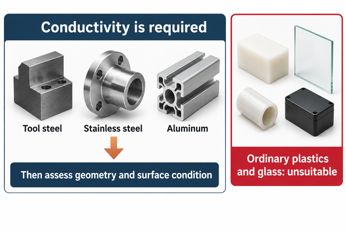
Conventional EDM requires a conductive workpiece, but conductivity is the first of many screens. Tool steel, stainless steel, and aluminum, for instance, can all be machined with appropriate equipment. The alloy, heat treatment, geometry and required surface condition determine whether EDM is the best manufacturing process.
What materials can EDM cut?
EDM can cut hard metals (difficult to machine with traditional cutting tools) and other electrically conductive materials. UWM lists steel, stainless steel and aluminum for its equipment. Ordinary insulating plastics and glass are unsuitable for conventional EDM. Conductive composites and specialized processes require assessment on a case-by-case basis.
Hardness and conductivity describe entirely different characteristics. A soft aluminum component may be easy to mill, while a hardened tool-steel insert may need a narrow feature that a milling cutter cannot reach reliably. Compare metal hardness and material condition before assigning a process from the alloy name alone.
EDM is commonly used for mold details where access or cutting forces can make conventional machining difficult. Manufacturers rely on EDM to fabricate some of these difficult forms after heat treatment. Its ability to machine hard materials can be useful when conventional cutters don’t work. However, this doesn’t alleviate the need to consider surface damage, inspect the feature and plan subsequent polishing.
With difficult-to-machine materials, pairing of the electrode and workpiece is critical. In micro machining, a small amount of tool wear can alter the feature being produced. A published study on micro-drilling from the University of Bergamo states that machining efficiency and tool wear depend on the electrode/workpiece pairing. Its tungsten-carbide micro drilling cost model depends on the tested pairing of electrode and workpiece. Changing either member of the pairing alters the cost comparison.
Feature-to-Process Map: EDM or milling?
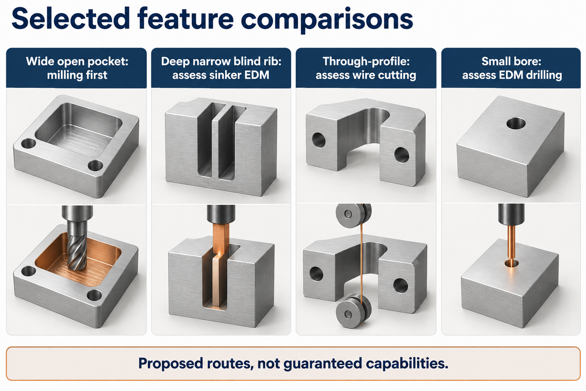
Feature-To-Process Map correlates geometry and acceptance conditions with a proposed machining route and drawing action.
Typically start with the feature that most constrains the job. Standard machining may already satisfy most of the drawing requirements. Conventional machining methods may still be useful for removing accessible stock, while EDM allows details that may be difficult to reach with a tool. A combined route may remove the bulk of the stock with one process and finish the feature with the other.
| Feature or condition | Route to assess | Reason and limitation | Next action |
|---|---|---|---|
| Wide open pocket | Milling first | Direct cutter access makes bulk removal practical | Engineer: identify any detail that still requires EDM |
| Deep narrow blind rib | Assess sinker EDM | A shaped electrode can reach details difficult to machine using traditional cutters | Engineer: mark depth, width and allowable corner radius |
| Hardened cavity with accessible bulk | Milling plus sinker finishing | Reserve EDM cutting for the remaining detail | Planner: agree the stock left for the burn |
| Through-profile | Assess wire cutting | A traveling wire follows an accessible through-path | Engineer: provide start access and retention plan |
| Small bore | Assess EDM drilling | Electrode access differs from a full cavity burn | Quality: define depth and breakthrough acceptance |
| Very small internal corner | Compare sinker with a design change | Electrode geometry, spark gap and wear limit reproduction | Engineer: specify a finite acceptable radius |
| Thin or flexible feature | Assess EDM with a holding plan | Low cutting contact does not prevent stress release or movement | Planner: identify support and final inspection state |
| Surface-critical fatigue feature | Select route with quality review | Texture alone does not establish metallurgical condition | Quality: define the required surface-integrity evidence |
| Electrically insulating workpiece | Choose another process | Conventional EDM needs electrical conductivity | Engineer: assess milling, grinding or another suitable route |
What is the difference between CNC and EDM?
CNC means a machine is controlled by a computer. EDM means material is removed by an electric spark. An EDM machine may use CNC as well as a milling machine. CNC machining includes different removal mechanisms. The comparison is normally between EDM and milling, drilling or another cutting process, using the same drawing, material condition and acceptance conditions.
KU Leuven’s process-planning research compared micro-milling and micro EDM on a specific integrated platform. In the prismatic cavities studied, micro-milling was faster and more cost effective. For smaller cavities, time for micro-milling and EDM came closer. The suggested method was to use micro-milling for bulk removal, followed by EDM. This supports testing a combined route, not a specific size at which one process wins.
For an accessible pocket with a small detail at the bottom, compare milling operations for most of the volume and define the last burn with EDM. If the drawing permits a larger internal radius, then a design change may eliminate the need for EDM. Agree that design change before making the shaped electrode.
The advantages and disadvantages of EDM differ from electrochemical machining. EDM removes material through electrical discharges and thermal erosion. Electrochemical machining uses dissolution in an electrolyte. Neither should be referred to as simply “non-contact machining” when the final surface is of concern.
Sinker EDM workflow: electrodes, flushing and finishing
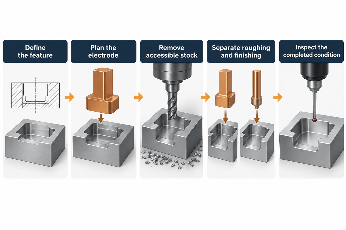
In sinker EDM, the electrode and burn sequence are determined by working backward from the cavity and its acceptance conditions. Electrode preparation, roughing, and finishing are separate operations. Inspection is a separate task. Change of the surface finish requirement can impact the time required and the tooling plan. EDM is used at different discharge settings for roughing and finishing.
- Define the feature. Identify datum, alloy condition, corner geometry and any surface-integrity requirement.
- Plan the electrode. Allow for the gap, wear and access needed to clear debris.
- Remove accessible stock. Use the agreed pre-machining route before the detailed burn.
- Separate roughing and finishing. Choose electrodes and process parameters for each stage.
- Inspect the completed condition. Include any polishing or subsequent operation in the acceptance plan.
A stable EDM system requires more than generator power. The limitations of electrical discharge machining include the ability to clear debris from the gap. Debris trapped in a narrow gap can cause abnormal discharges, and electrode wear and loss of precision. Yu, Rajurkar and Shen’s micro-hole research describes this limitation and a planetary-motion flushing approach. A special demonstration is not permission to assume that every deep blind feature will flush successfully.
“Flushing is the number one rule in EDM.”
The same interview states the value of separating roughing from finishing, and the cost of running an electrode too long. For procurement, the question should be “how will the supplier maintain final geometry through the batch” rather than “how few electrodes will be on the quote”.
EDM power settings influence the job. Increased discharge energies may increase removal but also increase wear; low discharge energy used in the finishing process affects time calculation. Machining parameters used on one electrode shape may not perform the same on the other. The machine used, starting finish and the path available to remove the debris all belong in this discussion.
EDM accuracy and surface integrity
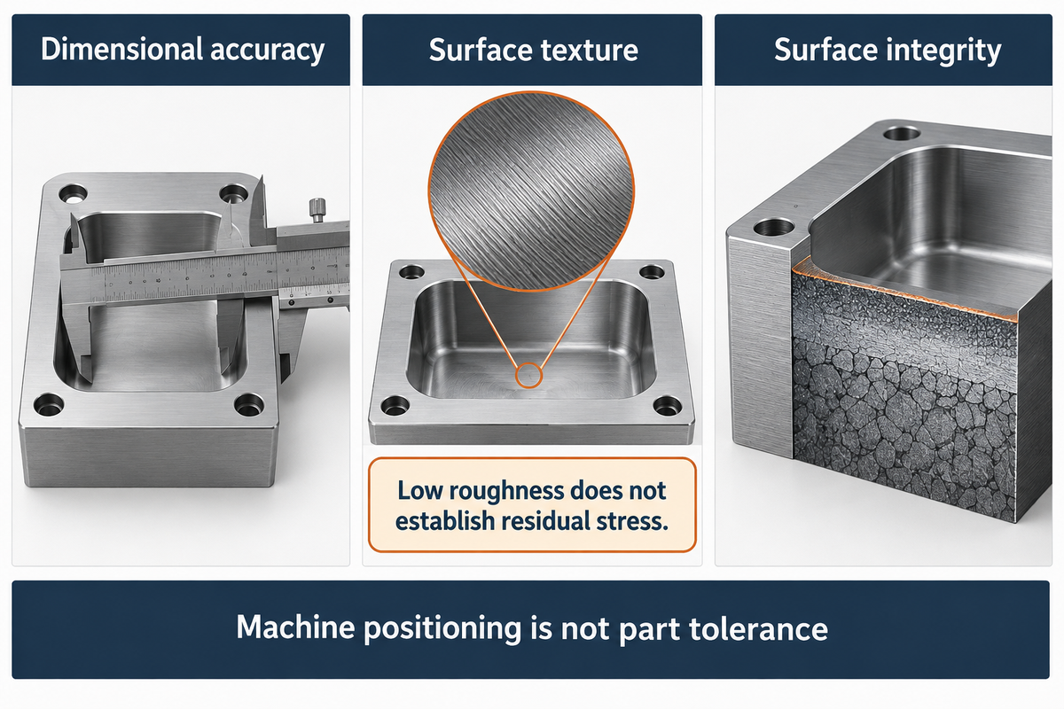
Dimensional accuracy, texture and surface integrity should be specified separately. A low roughness value can’t determine the residual stress state and a machine positioning number can’t establish the tolerance of a finished cavity. Inspection must address the actual feature after the complete agreed sequence, including any polishing or other finishing.
With the correct equipment and settings, EDM can achieve (fine) finishes. The sinker-machine catalog of Makino separates position accuracy and the best finish. Workpiece, electrode and acceptance conditions still need to be specified.
| Published category | Position accuracy | Best finish | What the figure does not establish |
|---|---|---|---|
| Micromachining | ±1.0 µm | 0.03 µm Ra | The size, form or surface integrity of an unspecified part |
| High precision / fine finish | ±1.0 µm | 0.05 µm Ra | A guaranteed result on every alloy and cavity |
| General precision | ±2.0 µm | 0.3 µm Ra | The inspection uncertainty of a supplier’s measurement |
| General precision / large | ±5.0 µm | 0.3 µm Ra | The effect of later polishing or stress release |
In NASA’s nickel-superalloy study, roughness was observed to decrease during the transition from rough to finish conditions. Additionally, tensile residual stress was observed to increase. The results addressed the specific wire process and alloys being tested, and not other sinker operations being performed. It demonstrates the risk of relying on appearance or roughness for accepting fatigue-sensitive features.
Another reason is release of stresses that may have been present in the stock. Research from Los Alamos discusses how new cut surfaces deform as residual stresses relax, even with low-stress cutting. In addition to these reasons, consideration must also be given to other previously mentioned factors: material condition, holding and the sequence of removal therefore matter alongside discharge parameters.
Transform the drawing tolerance requirements into a dimensional inspection. Identify the required dimensions and datums, location of the roughness measurement, method of measurement, recast layer or metallurgical assessment. State whether the result is accepted before or after polishing.
Specify
- Define size and form on the drawing.
- State the roughness measurement location.
- Agree surface-integrity evidence where function requires it.
Avoid
- Substituting positioning accuracy for part tolerance.
- Accepting a bright surface as metallurgical proof.
- Leaving post-EDM material removal outside the scope.
EDM cost: separate tooling from part time
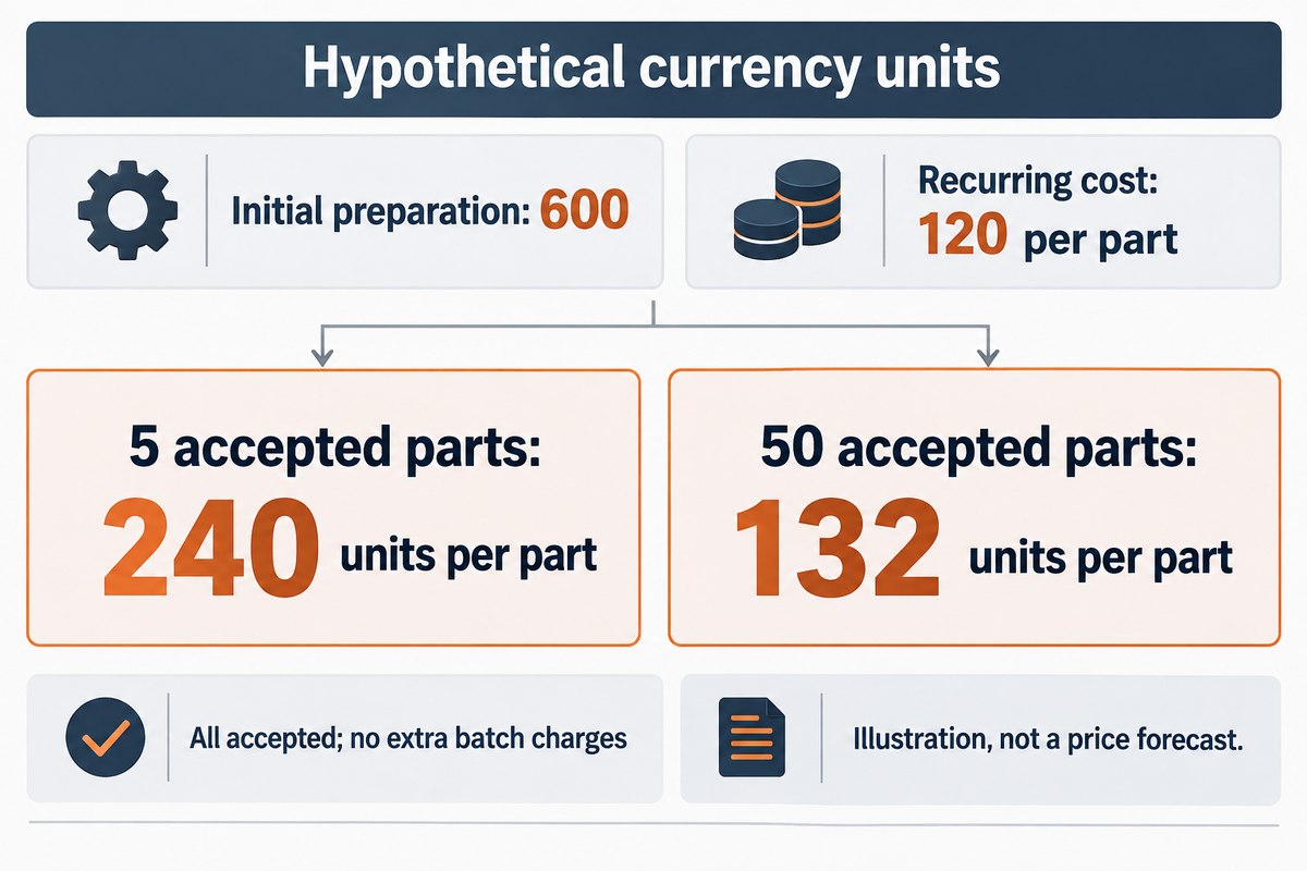
The Tooling-To-Part Cost Split separates initial tooling cost from repeated machining and consumption of EDM electrodes, allowing quotes to be compared at the same production quantity.
A meaningful EDM quote states what’s paid once, what repeats per part and what repeats per batch. Initial programming and electrode preparation may be shared across a batch. Replacement electrodes, face renewal, burn time and inspection occur with continued production. The cheapest electrode may not be the cheapest feature.
In Hannan and colleagues’ SS310 experiments, machining cost included electrode material consumed during the run and material removed to renew its face. Labor and depreciation depended on machining time. These are useful cost categories; the paper’s experimental prices aren’t current commercial quotations.
Take a hypothetical quote in currency units. Assume initial preparation F = 600 and recurring cost V = 120 per part and quantity Q. Assume the entire quantity is accepted and the tooling strategy supports Q; also, no batch charges are applied. Average cost per accepted part would be F/Q + V. The recurring cost would include electrode consumption, machining, finishing and inspection.
| Accepted quantity | Initial cost per part | Recurring cost per part | Average cost per accepted part |
|---|---|---|---|
| 5 parts | 120 units/part | 120 units/part | 240 units/part |
| 10 parts | 60 units/part | 120 units/part | 180 units/part |
| 15 parts | 40 units/part | 120 units/part | 160 units/part |
| 20 parts | 30 units/part | 120 units/part | 150 units/part |
| 25 parts | 24 units/part | 120 units/part | 144 units/part |
| 30 parts | 20 units/part | 120 units/part | 140 units/part |
| 40 parts | 15 units/part | 120 units/part | 135 units/part |
| 50 parts | 12 units/part | 120 units/part | 132 units/part |
| 100 parts | 6 units/part | 120 units/part | 126 units/part |
For 5 accepted parts, 600/5 + 120 = 240 currency units per part. For 50 accepted parts, 600/50 + 120 = 132 currency units per part. The calculation shows the effect of spreading an initial cost; it doesn’t predict a price and it doesn’t justify a larger order.
Finance may prefer the lower average while production needs only a short run. Extra inventory, drawing changes or a replacement electrode batch charge can change the purchase decision. Where yield is uncertain, divide the total cost by the number of accepted parts, instead of assuming that all started parts will be shipped.
Hidden bottleneck map: from electrode to accepted part
A hidden bottleneck map follows the job through tooling, burn, finishing and inspection to determine what activity controls the delivery.
| Stage | Potential delay | Question for the quote |
|---|---|---|
| Electrode manufacture | Tooling capacity or a revised cavity design | When will the rough and finish electrodes be ready? |
| Burning | Unstable flushing or conservative finishing settings | Which feature controls the burn time? |
| Finishing | Polishing or removal of an affected surface layer | Is this operation included and dimensionally accounted for? |
| Inspection | Inaccessible features or specialist testing | Which measurements or samples are needed before release? |
This breakdown can assist the production manager to determine whether the machine queue or the preparation of electrodes actually controls delivery. Purchasing should compare the same finished condition across quotes. Identify the machining process used at each stage to ensure quotes include the full route. Quality should verify any offer that saves time by eliminating acceptance test requirements stipulated by the drawing.
EDM supplier selection and drawing checklist
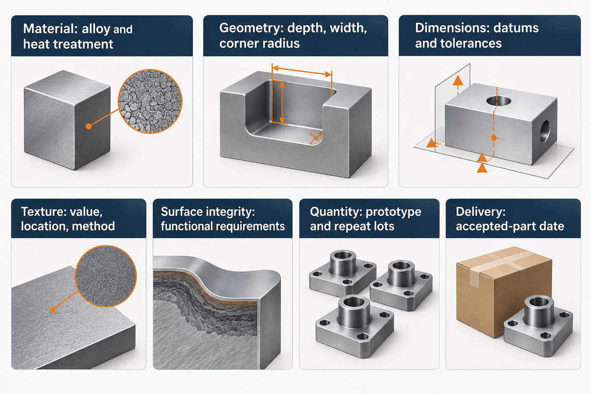
Choosing an EDM supplier is based on evidence for the required feature, as well as the proposed production sequence. A machine list is helpful, but the quote should address electrode planning and dimensional and surface finish inspection. Clarify which operations are performed in-house and which depend on another supplier.
What should I compare before choosing an EDM supplier?
Ask for the proposed production route, tooling, inspection and delivery breakdown for the same drawing revision. Rather than requesting general claims for precision, ask how the supplier plans to address the critical feature. For a repeat order, ask how electrode replacement and wear have been considered in the cost.
| Input | What to specify | Why it changes the quote |
|---|---|---|
| Material | Exact alloy and heat-treatment condition | Changes the electrode pairing and process plan |
| Geometry | Depth, minimum width and allowed corner radius | Determines access and flushing constraints |
| Dimensions | Datums, critical tolerances and inspection state | Defines what must be measured |
| Texture | Roughness value, location and measurement method | Sets finishing and inspection work |
| Surface integrity | Any functional recast-layer or metallurgical requirement | May add testing or secondary removal |
| Quantity | Prototype, first lot and repeat-lot expectations | Separates initial and recurring costs |
| Delivery | Required accepted-part date and documentation | Exposes tooling and inspection bottlenecks |
Use the first-article inspection scope to determine the documents required for release. A first-off dimensional report may be different from the qualification of the production process. Combine the current model and drawing, and determine which document governs the conflict.
Dielectric handling also belongs in supplier qualification. A published study of EDM aerosol emissions and fire risk found that operating conditions affected both. Ask about the machine’s intended dielectric, ventilation and protective controls. ISO 28881:2022 addresses machine safety; it is not a certificate that a supplier can hold your part tolerance.
Obtain these drawing inputs for a machining quote before price comparisons. A subtle difference in a corner radius or surface finish requirement may change the proposed route in a quote more than a small difference in hourly rate.
EDM outlook: adaptive flushing still needs part qualification
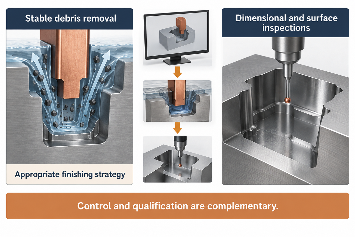
In general, better controls are helpful when they address the constraint in the part being produced. For a deep cavity part, stable debris removal and an appropriate finishing strategy may be more valuable than a generator with a high maximum output. Judge the proposed machine by the complete feature and acceptance.
Makino states adaptive jump flushing and ES200A digital generator are means to reduce electrode wear and improve debris removal. Determine what control function changes the proposed route for your geometry.
The 2011 Modern Machine Shop report on spark control describes the need for both adjustment and monitoring of wire EDM machines based on the material. Steve Bond, national sales manager at Methods Machine Tools, quoted in the report also recognizes that EDM is a thermal process. This example illustrates that automatic control and surface qualification are complementary.
EDM performance: compare the expected changes of electrodes and inspections for high-volume EDM work as well as the burn. A stable sequence of EDM settings may result in better EDM performance. If a supplier offers to use a faster EDM cycle time, agree which dimensional and surface inspections will provide evidence that the function of the part is unchanged.
Frequently asked questions
What does EDM stand for?
EDM means electrical discharge machining: controlled spark erosion of conductive material.
EDM stands for electrical discharge machining, a process that removes material from a conductive workpiece with sparks. It is also called spark erosion or electric discharge machining. The name describes material removal, not how the axes are controlled: many EDM machines use CNC controls, as milling machines do. Electrode forms create different features.
What are the disadvantages of EDM?
Electrical discharge machining is used for difficult conductive features; its disadvantages include slower bulk removal, electrode wear and thermal surface effects.
EDM generally removes bulk material more slowly than milling, and sinker work needs electrodes. Electrode wear, flushing access and fine finishing can add time. The process creates thermal surface effects that may need inspection or removal. Conventional EDM requires electrical conductivity, so plastics and glass are unsuitable workpieces for this method.
How does a wire EDM machine work?
A wire EDM machine cuts through-features with a traveling electrode and controlled sparks.
Wire EDM feeds a wire electrode through the workpiece while controlled electrical discharges remove material across a gap. The wire follows a programmed path to create a through-profile. It is useful for outlines and slots; a closed-bottom cavity calls for another route, such as milling or sinker EDM, with access.
Who makes EDM machines?
Makino and Sodick manufacture EDM equipment for different machining applications.
Makino and Sodick are examples of EDM equipment manufacturers. Their machine ranges serve different feature sizes and production needs. A manufacturer name alone does not identify the appropriate model, electrode strategy or supplier capability for a particular drawing. Compare the proposed process.
Can EDM achieve micron-level accuracy?
At machine level, yes: Makino lists ±1.0 µm position accuracy for its micromachining and high-precision sinker categories, but holding a finished part to that level still takes a qualified process and inspection.
Some EDM equipment is designed for very fine positioning and finishes, but a catalog specification does not establish the tolerance of your finished part. Makino, for example, lists position accuracy and best surface finish as separate characteristics. Ask the supplier to qualify the drawing dimensions on the proposed material, geometry and process. The inspection method, temperature conditions and any finishing after EDM also matter. Specify acceptance explicitly.
Is EDM always burr-free?
EDM avoids many chip-cutting burrs, but the finished edge still needs acceptance criteria.
EDM avoids the conventional chip-forming cutting action associated with many machining burrs. That does not make every finished edge acceptable. Recast material, fragile edges and downstream handling can still require attention. Specify the edge condition and inspect the actual feature.
How fast do EDM machines operate?
Wire EDM speed is quoted as cut area per hour: one machine-tool buying guide says 24 to 37, and in some cases 45, square inches per hour is not uncommon on current machines; geometry, finish passes and sinker electrode work set the real job time.
Removed volume, material, electrode geometry, pulse settings, flushing and the required finish all influence machining time. Sinker work also requires electrode preparation and setup before the burn begins. Ask for a lead-time breakdown that separates those activities from finishing and inspection. A quoted machine-hour rate or maximum removal figure alone cannot tell you when a conforming batch will be ready for delivery. Include queue time in that schedule.
Prepare the feature before requesting the quote
Mark the difficult geometry, the material condition and the final acceptance requirements. Use the cost split to compare initial tooling with repeat-part costs, then ask the supplier to explain the proposed route and delivery sequence.
This guide synthesizes published research, manufacturer catalog information, and a purely hypothetical cost estimate. No customer production trial or proprietary machining information is presented.
References & Sources
- University of Wisconsin, Milwaukee: Electric Discharge Machining
- D’Urso et al., University of Bergamo: Cost Index Model for Micro-EDM Drilling (2017)
- KU Leuven: Development of Process Planning Tools for EDM Operations
- Yu, Rajurkar and Shen: High Aspect Ratio and Complex Shaped Blind Micro Holes by Micro EDM (2002)
- Canadian Metalworking: 6 Electrode Wear Mistakes in Sinker EDM
- NASA Glenn Research Center: EDM Surface Conditions of Nickel-Based Superalloys (2023)
- Los Alamos National Laboratory: Contour-Method Cutting Assumption (2010)
- Hannan et al.: Machining Performance and Economic Analysis of SS310 EDM (2024)
- PubMed: Study of EDM Aerosol Emissions and Safety
- International Organization for Standardization: ISO 28881:2022
- Modern Machine Shop: Spark Control Pushes Wire EDM Boundaries