How to Plan and Verify Milling Operations Before Release

Milling Operations Planning and Verification describes the procedure to connect a drawing requirement to a controlled setup, qualified cuts and evidence that the drawing requirement is met. The name of the operation by itself doesn’t ensure access for the cutter, rigidity, suitability of the parameters, conformance to dimensions and stability of the process. The plan records the decisions that transform an operation to a confirmable process.
The guide begins after selecting a broad operation family. The focus is on planning for engagement, datum selection, workholding, machine limits, prove-out, a first piece inspection, and troubleshooting. This guide isn’t a guide on the various milling methods, a supplier capability catalog, or a source of cutting data. Thinking along these lines differentiates this guide from Zhenling Metal’s other milling operations guide.
Key takeaway
The name of the process indicates a method of cutting, but does not verify that the selected tooling, setup, parameters and inspection will produce an acceptable part.
What Does a Milling Operation Plan Need to Prove?
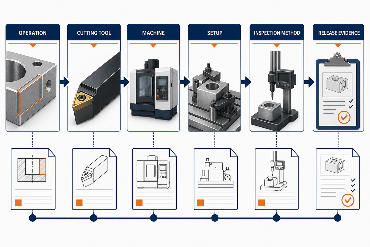
Milling operations planning must demonstrate that the selected method of cutting can access the feature, is stable in the setup, and produces evidence for the release. It relates the drawing, cutter, holder, workholding, machine Limits, material, factor relationships, and inspection. If any of the relationships is assumed rather than verified, the name of the operation isn’t sufficient.
Keep three things separate. The operation explains how a feature is generated. The cutting tool introduces edge geometry and engagement. The machine gives us axes, spindle motion, control, and structural support. An end mill is a tool, not a complete plan. The same tool can support slotting, profiling, pocket milling, thread mill work or finishing operations when access and engagement allow.
Face milling, peripheral milling, plain milling, side milling, straddle milling, gang milling, form milling, angle milling, gear milling, saw milling, slot milling and profile milling are useful terms, but are upstream inputs and aren’t the subject of this manual. Each vertical milling machine, horizontal milling machine, universal milling machine, manual milling machine or CNC milling machine needs the same documented relationship among feature, datum, cutter, setup and acceptance evidence.
Scope boundary:
In broad reference usage, milling is a subtractive manufacturing process and, more specifically, a machining process in which rotating tools remove material. General explainers may organize the types of milling operations as 12 types of milling operations, main types of milling operations, various types, common CNC milling operations, milling machine operations, an end milling operation or other machining operations; milling is often one stage in a broader manufacturing sequence. They may also explain milling techniques, how CNC milling works, how milling and drilling differ, or where a CNC milling process fits among cutting operations and secondary operations.
That classification vocabulary can include face milling and peripheral milling, slab milling, angular milling, side milling cutters, 3-axis milling, bed-type milling, planer-type milling and vertical and horizontal milling. It can compare horizontal and vertical milling machines, also phrased as vertical and horizontal milling machines, or discuss milling technology and different operations. Any of those categories are inputs to milling operation selection. No list can choose the right milling operations for actual milling tasks, prove that one common milling operation is sufficient, determine when milling is best or compare cnc milling services. This manual starts after the operation used for the feature has been presented.
Which Inputs Belong in Milling Operations Planning and Verification?
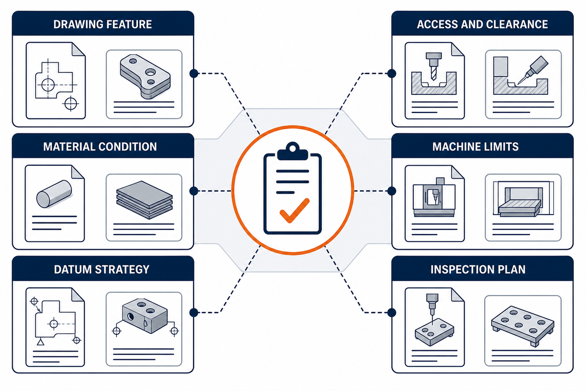
milling operations planning and verification work best when every release decision includes an input, a question, and a record. The table below shouldn’t be used as a feature-to-operation selector. Assuming the operation family has been selected, it shows what remains to be qualified for either a cutting or production release.
| Feature planning input | Operation-family planning question | Release evidence |
|---|---|---|
| Drawing feature | What geometry, tolerance and surface requirement must the operation create? | Controlled revision and feature acceptance list |
| Material condition | What alloy, heat treatment, hardness, scale or work-hardening behavior is present? | Material record and qualified tool guidance |
| Datum strategy | Which references locate the feature through every setup? | Datum map and transfer check |
| Access and clearance | Can cutter, holder and probe reach without collision or excessive overhang? | Access review, simulation and measured projection |
| Tool and holder | Do edge geometry, flute space and interface suit the material and engagement? | Tool identity, holder identity and runout check |
| Engagement and direction | Where does each edge enter, cut and exit, and how does force travel through the fixture? | Toolpath review and direction record |
| Machine limits | Are speed, torque, power, feed, travel and control behavior compatible? | Limit check against the actual machine |
| Controlled prove-out | How will the first execution expose setup, program or chip-control errors safely? | Approved prove-out record and observations |
| Inspection plan | Which measurements demonstrate feature and datum conformance? | First-piece report, method and traceable result |
In NIST’s feature-based process-planning work, features are considered as formal planning inputs, on the other hand, NIST IR 5808 shows that the determination of setups and selection of machining resources are interconnected. The practical consequence is narrow, but important. Selection of an operation doesn’t conclude the endeavor of planning. Access, equipment, workholding, process control, and inspection must also be aligned with evidences.
Climb Versus Conventional Milling: What Actually Changes
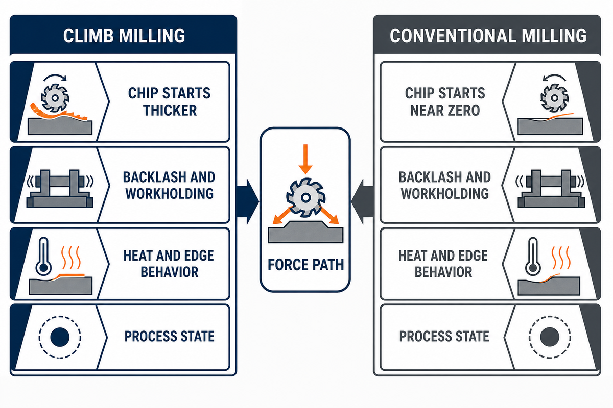
Conventional milling and climb milling change the direction of feed relative to cutter rotation at the contact zone. In conventional milling, the initial chip thickness at the entry is almost zero, while in climb milling it’s almost the maximum and is reduced. This difference affects both chip formation and the direction of the cutting force, but doesn’t select a safe method on its own.
Climb milling
- Chip starts thicker and becomes thinner
- Cutting force tends to draw the work into engagement
- Backlash control and secure workholding are critical
- Often evaluated for a finishing pass on capable equipment
Conventional milling
- Chip starts near zero and becomes thicker
- Initial rubbing can affect heat and edge behavior
- May be considered for backlash or difficult-skin conditions
- Can be used as a light corrective finish in some situations.
Both columns present possible results, not a definitive recommendation. Machine condition, control response, workholding, cutter geometry, material, wall thickness and rigidity, and the purpose of the pass can all produce the opposite result. One peer-reviewed thin-wall study documented modeled conditions in which up-milling (conventional milling) was more stable than down-milling (climb milling). DATRON, a tooling supplier, also documented a case in which a light conventional finish could account for deflection after climb roughing.
To determine the direction of the cutting force, test the entire force path. Account for fixture resistance, controlled backlash, the edge engagement of a hard skin or an interrupted surface, wall flexibility, and if the thin wall moves with the tool. Record the selection of the direction in the process state as, otherwise, troubleshooting may compare unlike cuts.
Geometry Becomes a Setup: Access, Axes, Datum and Workholding
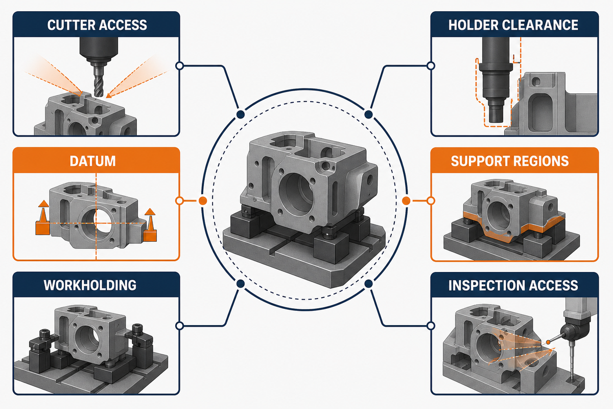
Cutter reach alone does not establish manufacturability; the workpiece must also be located, held and matched to the available machining resource. The starting point is usually the functional datum system. Once that’s established, consider which faces are accessible in one position, where a tool or probe could be blocked by a clamp, and which faces could be distorted by forces. A 3-2-1 locating scheme can be helpful in establishing the six degrees of freedom, but in the end, the actual clamping and contact must match the design.
Three-axis CNC machining may require several repositionings to reach all sides. An indexed fourth axis could provide another orientation without simultaneous rotary cutting. Five-axis motion can change tool orientation continuously or position the part for access, depending on the machine and program. Fewer setups can reduce datum-transfer opportunities, but they do not eliminate the possibility of error. Rotary-axis calibration, fixture reach, collision clearance and tool center point behavior are just a few of the many issues still present.
Tool reach is also a balancing act. It’s obvious that a shorter tool would be stiffer, but overhang due to deep pockets, tall bosses, and clamps may be necessary. Unsupported workpiece walls can move under radial force and will spring back when the edge passes. Thus, access cones, holder clearance, critical support regions, datum transfers and inspection access must be shown in the plan before code release.
Manual milling involves the same geometry and restraint problems even when the operator controls the movement. A vertical milling machine and a horizontal machine offer different spindle and arbor arrangements, yet either type of milling machine must establish a stable relationship among cutter, workpiece and datum. Like all other vertical mills, there is the possibility of access, support, or datum transfer errors. The setup is the physical argument that the programmed or hand-fed motion can become the intended surface.
Parameters Are a System, Not Four Isolated Numbers
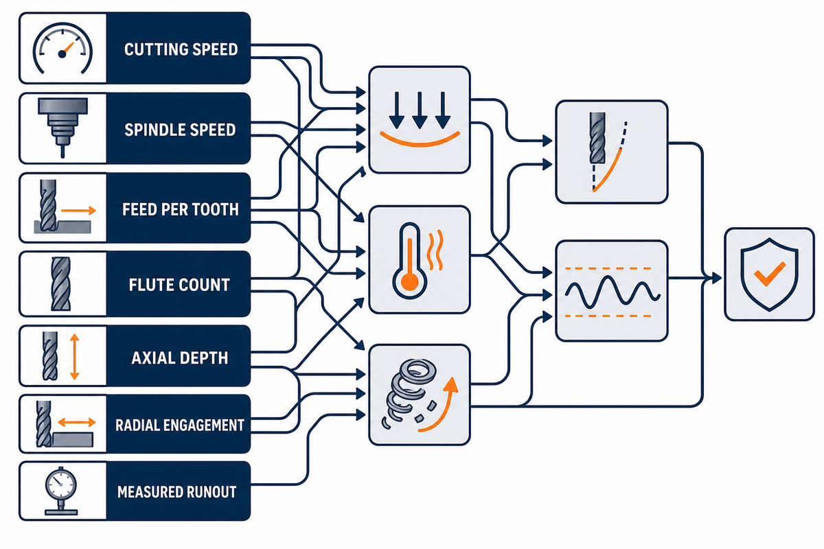
When taking into account the cutting speed, spindle speed, feed per tooth, programmed feed, axial depth of cut and radial engagement, things quickly get complicated. As a general case, spindle speed is equal to the cutting speed divided by the circumference of the cutter, and programmed feed is equal to spindle speed multiplied by the number of flutes and feed per tooth. These equations describe relationships; they do not provide default values or account for every machine or tool limit.
Radial engagement changes the arc over which an edge cuts, while axial depth changes how much edge length participates. At low radial engagement, the programmed feed per tooth and the maximum chip thickness are not the same quantity; chip-thinning compensation may be considered within qualified tool guidance. Increasing either engagement changes cutting forces, heat, deflection, stability and chip evacuation, so these considerations must be made all at once.
Relationship example, not a setting: if an illustration uses 100 m/min cutting speed and a 10 mm cutter, the basic circumference relationship gives about 3,183 rev/min. At 0.05 mm/tooth with four flutes, the corresponding arithmetic gives about 637 mm/min feed. Real values must come from qualified tool data and a validated setup.
| Record field | Trial A | Trial B |
|---|---|---|
| Tool diameter | 10 mm | 10 mm |
| Measured projection | 30 mm | 30 mm |
| Axial engagement | 12 mm | 12 mm |
| Radial engagement | 1 mm | 2 mm |
| Cutting speed | 100 m/min | 100 m/min |
| Spindle speed | 3,183 rpm | 3,183 rpm |
| Feed per tooth | 0.05 mm | 0.05 mm |
| Programmed feed | 637 mm/min | 637 mm/min |
| Measured runout | 0.01 mm | 0.01 mm |
Only radial engagement changes in this hypothetical pair. The record shows how to isolate a comparison, not what either trial should use. The required limits and starting values need the actual tool, material, holder, machine, and approval process.
Runout redistributes load among flutes. One flute may engage heavily while another engages less even though they’ve the same average programmed feed. Four factors affect this dynamic system – Tool overhang, holder condition, spindle interface, and workholding rigidity. Coolant delivery, air blast and chip evacuation affect recutting and heat, while material hardness, scale, inclusions or work-hardening behavior affect the edge.
These ratios show why some parameters can’t be separated from the geometry. Let’s say we’ve a 10 mm tool with a 20 mm tool overhang. A hypothetical 10 mm tool held with 20 mm of overhang doesn’t present the same bending condition as the same tool held with 60 mm of overhang. Additionally, changing the radial engagement from an example of 1 mm to 3 mm changes the contact arc even if the programmed feed is the same. These aren’t recommended values. They describe what state variables need to be included with the test result. A good example of a set up sheet includes the nominal tool diameter, the measurements, axial and radial engagements, and the number of flutes and holder identification and material condition in order to compare the results of the next setup with the previous setup.
Begin with qualified advice from the cutter supplier for the correct tool grade, shape, and material group. Check spindle power, torque, speed and axis-feed limits. Then, use a controlled trial with an acceptance plan. If the process changes, record the tool, holder, overhang, material lot or condition, engagement, direction, coolant strategy and measured result. All these factors, including engagement, should be documented each time the cut is repeated. Repetition of milling would be less of a problem, and it would reduce the burden of having to remember the steps involved in milling.
A copied speed-and-feed value is only a starting input. The released process is the documented combination of tool, engagement, setup, machine limits and measured output.
Use the 6-Face Operation–Setup Evidence Prism Before Release
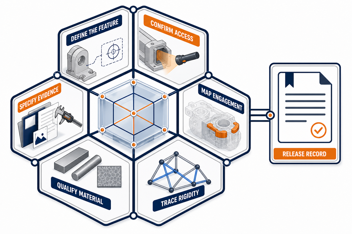
The Operation–Setup Evidence Prism is a post-selection audit; it does not select a supplier or replace process planning. It asks six linked questions after a suggested type of milling, cutter, and a setup have been identified.
- Define the feature — state the surface, geometry, datum and acceptance requirement the operation must create.
- Confirm access — check whether cutter and holder can reach without excessive overhang, obstruction or collision.
- Map engagement — identify where each edge enters, cuts and exits, including changing radial contact.
- Trace rigidity — identify what can deflect, vibrate, lift, shift or transfer error.
- Qualify material — account for alloy, heat-treatment condition, hardness, scale and chip behavior.
- Specify evidence – name the simulation, prove-out observation, measurement and in-process check used to accept the result.
The value of the Prism is in the connections. The pocket may be geometrically reachable, but may require a long tool. That access decision changes rigidity. Low radial engagement may help load, but it changes chip thickness. Stable sound may suggest improvement, but it doesn’t prove that the wall is in location. Each face of the Prism should point to another face and to a record.
First-party context
Based on Zhenling Metal’s current company brief, its factory uses three-, four- and five-axis machining centers along with cnc milling, boring, grinding, turning, wire electrical-discharge machining and fabrication equipment. The equipment list provided doesn’t justify if a specific tolerance, finish or outcome of an operation can be achieved without a job specific drawing, material and setup. Zhenling Metal’s Custom Machining Services page provides a broader company-level scope, whereas this article provides an educational level guide.
Verification: Simulation, Prove-Out and First-Piece Inspection
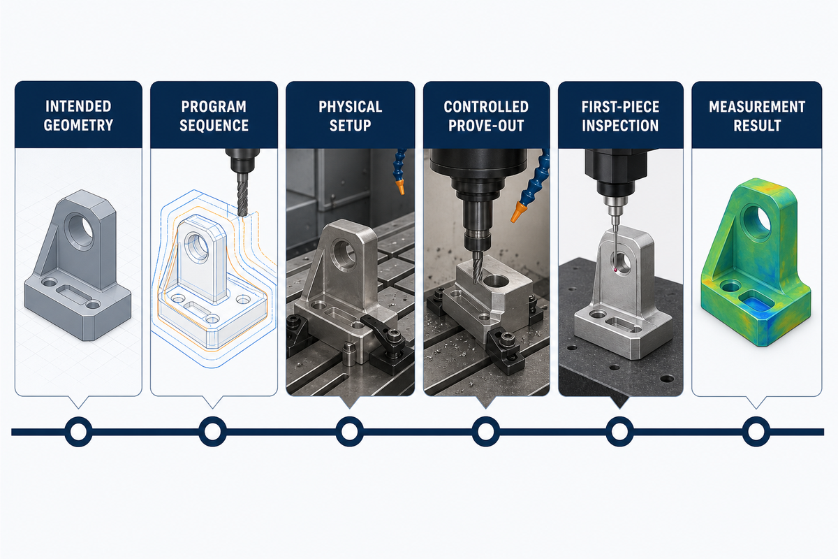
Four questions must be answered during verification. Is the intended geometry correct? Is the program or the manual sequence correct? Is the physical setup correct? Does measurement indicate that the drawing outcome was achieved?. A computer-aided manufacturing simulation may expose toolpath or holder collisions, but it cannot prove fixture rigidity, actual tool length, work offset, runout or material behavior.
Before cutting, confirm the revision, stock condition, datum, work offset, tool identity, holder, measured tool length and relevant machine limits. Use collision review where available. A controlled prove-out may use conservative overrides, single-block execution or other shop-approved procedures, with the operator clear of hazards and the machine guards functioning. Generic articles never override the machine builder’s procedures, training or site rules.
During first-piece inspection, prioritize high-risk rather than merely easy-to-measure dimensions. Evaluate the risk of damage, then measure the created feature’s position, size, form, wall condition and datum relationships with a method appropriate to the tolerance. Record the tool and offset state so a correction remains traceable.
One first piece within specifications does not guarantee continuous process capability. The NIST process capability framework evaluates the distribution of observations relative to the specification limits. Similarly, NIST’s metrological-traceability guidance explains that traceability belongs to a measurement result through a documented calibration chain; traceability alone does not prove fitness for purpose because measurement uncertainty still matters.
Safety evidence has its own domain. OSHA’s machine-guarding rule explicitly includes milling machines in equipment that usually requires point of operation guarding. OSHA’s examples of hazardous energy distinguish normal guarded production from exposure that occurs during service or maintenance. Guarding and control of hazardous energy are required and are related, but separate safety requirements. The applicable procedure is determined by the trained personnel for the specific task and jurisdiction.
Troubleshooting Milling Operations by Symptom
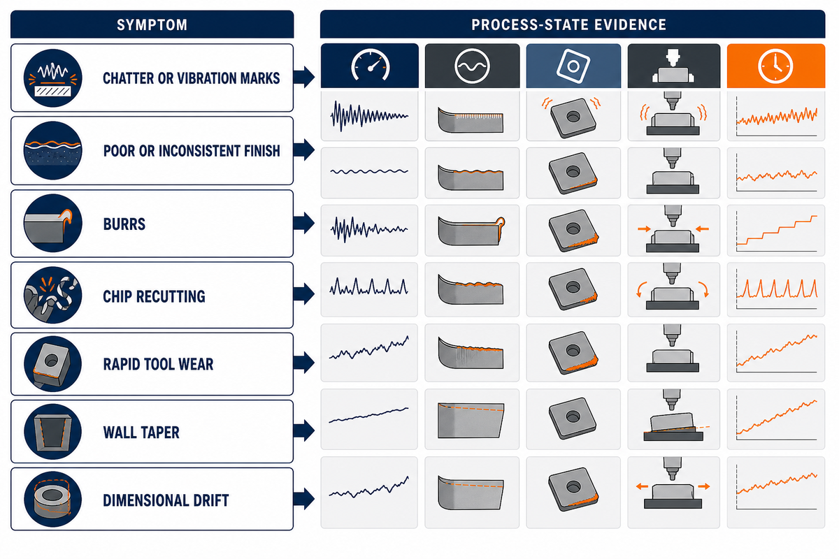
Troubleshooting compares the full process state. Each symptom is evidence of a mismatch, not proof of a singular cause. When practical, change one controlled variable at a time in the process. Record the result and keep safety and equipment limits outside the experiment.
| Symptom | Plausible contributors | Evidence to compare |
|---|---|---|
| Chatter or vibration marks | Overhang, weak support, engagement, spindle-speed region, worn edge | Tool/holder setup, stability trial, surface location and spectrum if available |
| Poor or inconsistent finish | Runout, built-up edge, chip recutting, deflection, direction, insert seating | Flute load, edge condition, runout, chip path and finish by location |
| Burrs | Exit direction, edge wear, ductility, unsupported edge, toolpath sequence | Burr location, entry/exit map, tool wear and material condition |
| Chip recutting | Confined pocket, poor evacuation, unsuitable flute space, delivery direction | Chip shape, pocket accumulation and coolant or air path |
| Rapid tool wear | Heat, hard skin, excessive load, rubbing, runout, grade mismatch | Wear mode by flute, chip color, material state and engagement history |
| Wall taper | Tool deflection, wall motion, holder clearance, uneven stock, wear | Size at multiple heights, stock allowance, overhang and pass sequence |
| Dimensional drift | Thermal change, tool wear, offset practice, fixture movement, measurement | Time-ordered results, environment, offsets, datum checks and gauge status |
Machine-tool chatter and dimensional error also need to be addressed separately. A study published in an ASME journal reports that a milling process can be chatter-stable while still showing surface-location error near resonant spindle speeds. Quiet cutting is informative, but doesn’t prove dimensional compliance. Runout can also redistribute chip load and introduce frequency peaks, thereby complicating the reasoning.
Do
- Compare a complete process-state record
- Inspect the edge and chips by location
- Measure the feature where error is likely
- Change one qualified variable at a time
Don’t
- Diagnose every mark as chatter
- Assume a quiet cut is dimensionally correct
- Copy an unqualified parameter correction
- Treat appearance as proof of service performance
Not all specified surface-Integrity or service-performance requirements are met by dimensional conformity and appearance. If the drawing, customer specification or application demands further constraints e.g. roughness, hardness, residual stress, cleanliness, nondestructive examination, then these need their own qualified process and acceptance criteria.
When an Educational Guide Becomes a Manufacturing Review
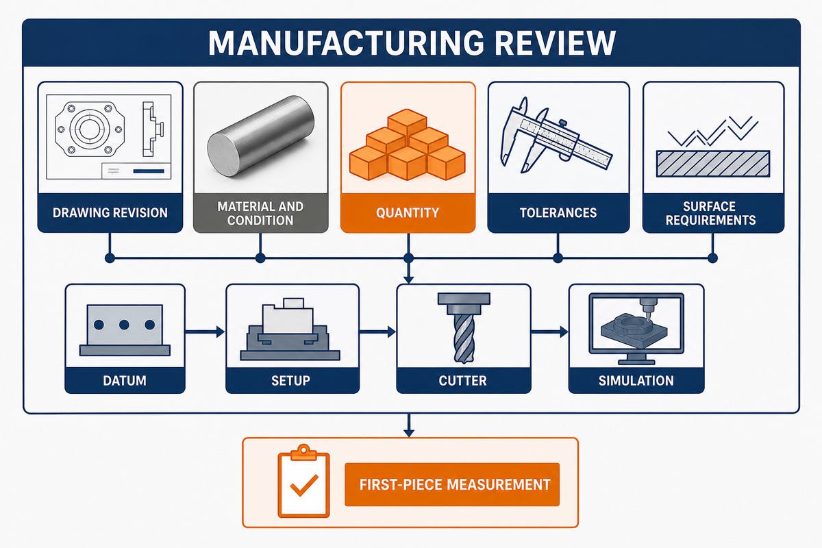
General guides can help organize questions but can’t supply a real answer. Something like a deep pocket with a tight corner in a machine shop can skew tool reach and wall deflection as the most significant risks in this scenario. The manufacturing inspection should note how each datum, setup, cutter, simulation, and first-piece measurement will confirm compliance with the drawing.
Once you’ve a drawing revision, material and condition, quantity, tolerances, surface requirements and inspection expectations, the task becomes a manufacturing review. You can review Zhenling Metal’s milling-operation solution for that commercial evaluation. Keep the educational taxonomy and the job-specific capability decision separate.
Frequently Asked Questions
What should a milling operation plan contain?
Answer
It should identify the controlled drawing revision, material condition, feature and datums; the machine, tool, holder and measured projection; workholding, access and engagement; starting parameters from qualified guidance; the prove-out method; and the inspection evidence required for release. The plan should also define which changes require another review and who owns each release decision.
How do you verify a milling setup before the first cut?
Answer
Confirm the stock, datum, fixture contact, clamp clearance, work offset, tool identity, holder, measured tool length and machine limits. Review tool and holder motion for collisions where suitable simulation is available. Follow the machine builder’s instructions and the shop’s approved prove-out and safety procedures; a generic checklist cannot replace them.
Does simulation verify a milling operation?
Answer
Simulation verifies only part of the plan. It can reveal programmed motion, geometric interference and some tool or holder collisions when the underlying model contains sufficient detail. It cannot by itself prove actual offsets, fixture rigidity, runout, material response, tool condition or dimensional conformance. Physical setup checks, a controlled prove-out and appropriate measurement are still needed.
What should first-piece inspection check after milling?
Answer
Prioritize the characteristics that carry the highest manufacturing risk: the created feature, its datum relationships, wall position or taper, form, size and nearby areas that could be damaged. Use a measurement method with suitable resolution and uncertainty, and record the tool and offset state so any correction remains traceable.
When must a milling operation be reverified?
Answer
Reverification is necessary if there have been any controlled input changes such as a drawing revision, grade/condition of material, machine, fixture, tool, holder, measured projection, engagement, direction, program, offset method, coolant strategy or inspection method. The first step is to understand why the change occurred and the risk that it poses. The tool being replaced with the same controlled specification may require a more limited review compared to a fixture or datum, where a new material condition can even posses a new risk of changing the behavior of the cut. The control plan needs to document who has the approval for the review scope, what characteristics are remeasured, and what final outcome allows the release of the product. This means that when new evidence is reviewed, it is dealing with the risk introduced by the change, not specific checks.
Why can the same planned milling operation produce different results?
Answer
An operation name does not fix the machine, tool, material, setup or process state. Changes in runout, overhang, holder condition, support, radial engagement, chip evacuation, coolant delivery, hardness and measurement method can alter finish, size and tool life. Compare complete, time-stamped records rather than assuming that the shared operation name guarantees repeatability.
References & Sources
- NIST, Feature-Based Process Planning Based on STEP
- NIST IR 5808, process-planning activity model
- The Open University, Multipoint Cutting: Rotational
- IIT Kharagpur/NPTEL, Milling cutters and operations
- ASME, Machine Tool Chatter and Surface Location Error in Milling
- OSHA 1910.212, General Requirements for All Machines
- OSHA, Machine Guarding and Hazardous-Energy Examples
- NIST Engineering Statistics Handbook, Process Capability
- NIST, Metrological Traceability
ABOUT ZHENLING
Custom machining from drawings and samples
Shanghai Zhenling Hardware Co., Ltd. was established in 2006. Its Jiashan, Zhejiang factory covers an 8,000 m² site with a 6,000 m² workshop for custom machined metal parts.
The team works from drawings and samples for applications including pressure vessels, oil-gas separation, and fluid control. Material experience includes carbon, alloy, and stainless steels as well as special alloys.
- 3-, 4-, and 5-axis CNC machining
- Grinding, wire cutting, and welding
- Domestic and export divisions
CONTACT PROFILE
Company details
- NAME
- Shanghai Zhenling Hardware Co., Ltd.
- ESTABLISHED
- 2006
- LOCATION
- Jiashan, Zhejiang, China
- FOCUS
- Custom machined metal parts from drawings and samples
- CAPABILITIES
- 3/4/5-axis CNC machining, grinding, wire cutting, and welding
- CONTACT
- Share the drawing, material, quantity, and critical requirements.