CNC metrology is a set of techniques and methods that embodies the entire process, from interpreting a drawing to making a measured decision. CNC metrology is composed of measured characteristics, conditions, traceability, uncertainty, results, decision rules, and evidence trails. It’s more than a Coordinate Measuring Machine (CMM) or figures expressed in a report.
Define
Name the feature, drawing revision, datum, part state, and decision.
Name the feature, drawing revision, datum, part state, and decision.
Measure
Choose a method that can reach the feature and produce the required evidence.
Choose a method that can reach the feature and produce the required evidence.
Decide
Interpret the result with its conditions, uncertainty, and agreed rule.
Interpret the result with its conditions, uncertainty, and agreed rule.
Instruments that resemble CNC metrology may evaluate process performance or product acceptance, but their application is limited to the purpose and procedure they support. Depending on the context of the result and the question being answered, a person knowledgeable in the area can make a decision based on the result.
Guide boundary
This article teaches measurement reasoning and evidence control. It does not set a project-specific tolerance, guard band, sampling plan, inspection frequency, or offset correction.
This article teaches measurement reasoning and evidence control. It does not set a project-specific tolerance, guard band, sampling plan, inspection frequency, or offset correction.
What CNC Metrology Includes
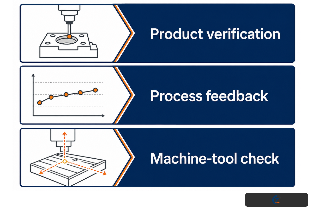
CNC metrology is machining-centered and spans product verification, process feedback, and machine-tool checks. It connects specifications, measurement methods, controlled conditions, results, and decisions, making it the science of measurement applied throughout the production process in modern CNC manufacturing. A CMM is just one route within that larger system.
| Purpose | Question answered | Typical evidence need |
|---|---|---|
| Product verification | Does the defined characteristic meet the applicable requirement? | Controlled result, tolerance, datum/state, method, and decision context |
| Process feedback | Is the machining process moving, stable, or in need of investigation? | Comparable repeated data, timing, setup identity, and trend context |
| Machine-tool check | Is the machine, probe, or kinematic condition suitable for its assigned task? | Defined test, reference, configuration, and maintenance or verification record |
The decision, not the instrument, sets the boundary of a given assurance method. It may be possible to locate a workpiece using different methods, evaluate a production feature using a fixed gauge, and assess a complex feature using a CMM; however, each method is limited to a specific purpose.
Key takeaway
If the purpose is unclear, the same number can be misused as setup confirmation, process evidence, and final acceptance. Define the decision owner before discussing equipment.
If the purpose is unclear, the same number can be misused as setup confirmation, process evidence, and final acceptance. Define the decision owner before discussing equipment.
In a CNC machine shop, machinists and quality control teams may measure throughout production to protect precision and keep the process repeatable, while tighter tolerances increase the need to define how each result will be used. These checks can cover machined parts, lathe or milling axes, spindle condition, and fixturing. Their evidence status still depends on the assigned procedure.
Industry context, not a capability claim
Aerospace and automotive programs can impose demanding document and acceptance controls, while other industries may use different risk rules. The guide does not infer a sector-specific approval from a generic measurement result.
Aerospace and automotive programs can impose demanding document and acceptance controls, while other industries may use different risk rules. The guide does not infer a sector-specific approval from a generic measurement result.
Start With the Measurement Question, Not the Instrument
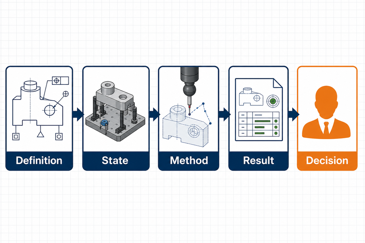
Measurement plans start with the client need and decision requirement; the instruction “measure this part” is incomplete until the drawing revision, units, part state, datum, measurand, and inspection purpose are identified.
The 5-Step Measurement Question Framework
1. Definition
Which controlled characteristic?
Which controlled characteristic?
2. State
Free, restrained, finished, warm, clean?
Free, restrained, finished, warm, clean?
3. Method
Which procedure can answer it?
Which procedure can answer it?
4. Result
What value or attribute is reported?
What value or attribute is reported?
5. Decision
Who applies which rule?
Who applies which rule?
Measurands can be different when derived from the same physical feature. For example, the axis position and cylindricity of a bore can be different measurands. The answer also depends on the part state and how the part is aligned, constrained, and supported.
Stop gate
Do not select a tool from the tolerance alone. Stop when the feature definition, datum, surface condition, part state, units, or decision purpose is missing from the controlled input.
Do not select a tool from the tolerance alone. Stop when the feature definition, datum, surface condition, part state, units, or decision purpose is missing from the controlled input.
The NIST inspection plan describes equipment selection for a measurement requirement as an information-flow problem. It’s important to evaluate the measurement question in the context of the system to be analyzed, to define the input, and ensure that available instruments will provide the required evidence.
Practical test
Before measurement, a qualified reviewer should be able to finish this sentence: “Using drawing revision [revision], evaluate [characteristic] relative to [datum] in the [part state] so that [owner] can decide [purpose].”
Before measurement, a qualified reviewer should be able to finish this sentence: “Using drawing revision [revision], evaluate [characteristic] relative to [datum] in the [part state] so that [owner] can decide [purpose].”
Match the Method to the Feature and Evidence Need

The best measurement method can reach the feature, control the dominant influences, and produce evidence suited to the decision. Sophistication alone doesn’t make a CMM, scanner, optical system, fixed gauge, hand tool, or on-machine probe the right choice.
The 6-Axis Method Fit Matrix
| Axis | Questions to resolve | Failure if ignored |
|---|---|---|
| Geometry | Size, form, orientation, location, profile, or texture? | A size reading is substituted for a geometric requirement |
| Access | Can the sensor reach and interact with the surface as required? | Hidden areas or edge effects are missed |
| Surface | Reflective, soft, rough, coated, burred, or interrupted? | The sensing principle changes the apparent feature |
| Evidence | Screening, numeric trend, geometry map, or release record? | Useful process data is mistaken for acceptance evidence |
| Conditions | Temperature, vibration, cleanliness, support, and cycle time? | The method is capable only outside the real environment |
Simple tools remain useful for taking measurements on the illustrative Example Shaft when the feature is accessible, the procedure is controlled, and the result suits the tolerance and decision; in that setting, simple tools can be the essential metrology tools. Complex form, inaccessible relationships, detailed surface data, or traceable coordinate results may justify coordinate measurement or a non-contact optical method, but those systems add setup, sampling, software, and interpretation choices.
Computed geometry is part of the method
Reported circles, planes, cylinders, and axes are often fitted from sampled points. Point distribution, filtering, outlier handling, association choice, and software implementation can therefore influence the reported feature.
Reported circles, planes, cylinders, and axes are often fitted from sampled points. Point distribution, filtering, outlier handling, association choice, and software implementation can therefore influence the reported feature.
GD&T, or geometric dimensioning and tolerancing, captures a designer’s intent and CAD definitions control it, but neither explains the inspection method. The surface of a part can be scanned and represented in a CAD model. Acceptance of inspection requires comparison of actual (designated) characteristics against the controlled requirements (mandates).
| Tool family | Useful question | Control boundary |
|---|---|---|
| Digital calipers or vernier caliper | Accessible external, internal, or depth size | Technique, contact, resolution, and feature form affect accurate measurements |
| Micrometer, dial indicator, or height gage | Defined size, comparison, runout, or height relationship | Reference, support, contact force, and surface plate condition matter |
| Fixed gage or protractor | Attribute screening or bounded angle check | The result carries less variable data and must match the requirement |
| Granite surface plate with accessories | Stable reference for comparative precision measurement | Plate grade, calibration, cleanliness, loading, and environment still apply |
| CMM, optical system, or 3D scan | Complex relationships or dense geometry | Sampling, fitting, alignment, software, and uncertainty remain part of the result |
Complex metrology tools aren’t required for every measurement. The complexity of a tool is determined by the system and its associated metrological requirements. Metrology is concerned with defining a measurement system, its method, and the reasoning behind the result.
Real-time does not mean self-authorizing
Real-time probe or sensor data can shorten feedback delay, yet the control plan must still define validity checks, permitted deviation, correction limits, and release ownership.
Real-time probe or sensor data can shorten feedback delay, yet the control plan must still define validity checks, permitted deviation, correction limits, and release ownership.
Measurement error and form error can both change a fitted result. NIST’s algorithms test cases are geared toward defining the computation path and reasoning for measurement. While software output can be actionable, it’s critical to define and control the reasoning, path, and associated computation that determine the measurement when the decision depends on them.
On-machine boundary
Probing can support workpiece setup, tool setting, selected feature checks, and process feedback before or during machining. Suitability for final acceptance still depends on the characterized machine-probe system, procedure, conditions, required uncertainty, independence needs, and agreed decision rule.
Probing can support workpiece setup, tool setting, selected feature checks, and process feedback before or during machining. Suitability for final acceptance still depends on the characterized machine-probe system, procedure, conditions, required uncertainty, independence needs, and agreed decision rule.
Build Confidence Beyond Instrument Accuracy
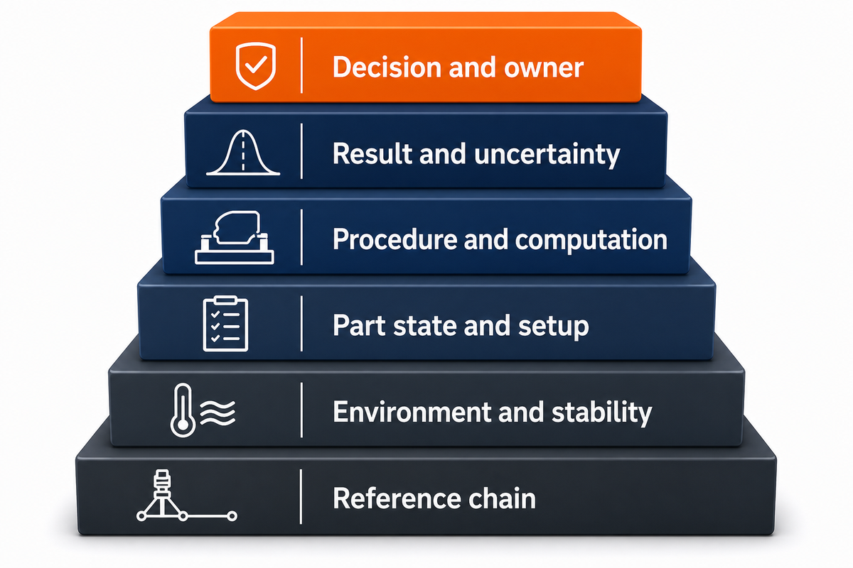
Measurement confidence covers a range of considerations including but not limited to stability, resolution, repeatability, reproducibility, setup, uncertainty, operator and environmental influences, and design rationale.
| Term | What it addresses | What it does not prove alone |
|---|---|---|
| Resolution | The smallest displayed or detectable increment | Accuracy or uncertainty |
| Repeatability | Variation under closely matched conditions | Agreement across operators or time |
| Reproducibility | Variation when defined conditions change | Long-term stability |
| Calibration | A documented relationship to references under stated conditions | Fitness of the whole part-measurement process |
| Uncertainty | Quantified doubt associated with a result | The acceptance rule or business consequence |
Uncertainty is quantifiable; accuracy, by contrast, is qualitative within measurement. A calibration report provides traceability and may help define reasoning for measurement. It doesn’t necessarily mean that environment, operator, setup, and system rationale are adequately defined for the feature under consideration.
The 7-Layer Measurement Confidence Map
Decision and owner who may conclude what
Result and uncertainty value, attribute, and quantified doubt
Procedure and computation alignment, sampling, filtering, fitting
Part state and setup surface, support, restraint, cleanliness
Environment and stability temperature, vibration, operator/configuration, drift
Reference chain identified standards and calibration relationships
Studies performed using NIST production gauges identify effects such as operator variation, gauge variation, and various types of errors including configuration, linearity, hysteresis, and drift. Because of these, a measurement system must be monitored over time, and it can’t be verified as permanently capable based on the results of a single study.
Avoid the ratio shortcut
Fixed “ten-to-one” rules are not universal substitutes for an uncertainty evaluation and decision rule.
The required capability depends on the characteristic, process risk, evidence purpose, and accepted false-decision exposure.
Control Part State and Measurement Conditions

Every dimension is connected to a particular part state and condition. Factors including temperature, burrs, contamination, the final condition of the part, how the feature is supported or restrained, recent machining and whether the part has fully recovered, and other variables can affect the part.
Condition-before-measure checklist
- Confirm the drawing revision, units, and characteristic definition.
- Verify whether inspection is required in free state or under a defined restraint.
- Remove burrs and contamination only under the approved part-handling rule.
- Record relevant part and environmental temperature information.
- Match support and clamping to the defined state without distorting the feature.
- Confirm that the measured surface condition is the contractual condition.
ISO 1:2022 establishes the standard reference temperature for geometrical and dimensional properties, including relevant measurands in specification and verification. It does not say that every useful shop-floor check must physically occur in a room held exactly at 20 °C.
Reference is not a room command
The important question is how the procedure handles the difference between actual conditions and the reference condition. Material expansion, gradients, part size, time, and required uncertainty determine whether a temperature difference is negligible, corrected, or disqualifying.
The important question is how the procedure handles the difference between actual conditions and the reference condition. Material expansion, gradients, part size, time, and required uncertainty determine whether a temperature difference is negligible, corrected, or disqualifying.
For the illustrative Example Shaft, results may answer the wrong contract question if the part is measured warm, restrained differently, or unfinished. Results are also inappropriate if the part is waiting for a coating or surface finishing process to change its controlled state. The drawing, specification, or agreed inspection plan must define the relevant part state.
Free-state boundary
Do not invent a fixture or restraint because an unsupported part moves during measurement. Escalate the missing state definition to the responsible design or quality authority and preserve the detailed fixture question for the dedicated topic.
Do not invent a fixture or restraint because an unsupported part moves during measurement. Escalate the missing state definition to the responsible design or quality authority and preserve the detailed fixture question for the dedicated topic.
Understand Traceability, Uncertainty and Decision Rules
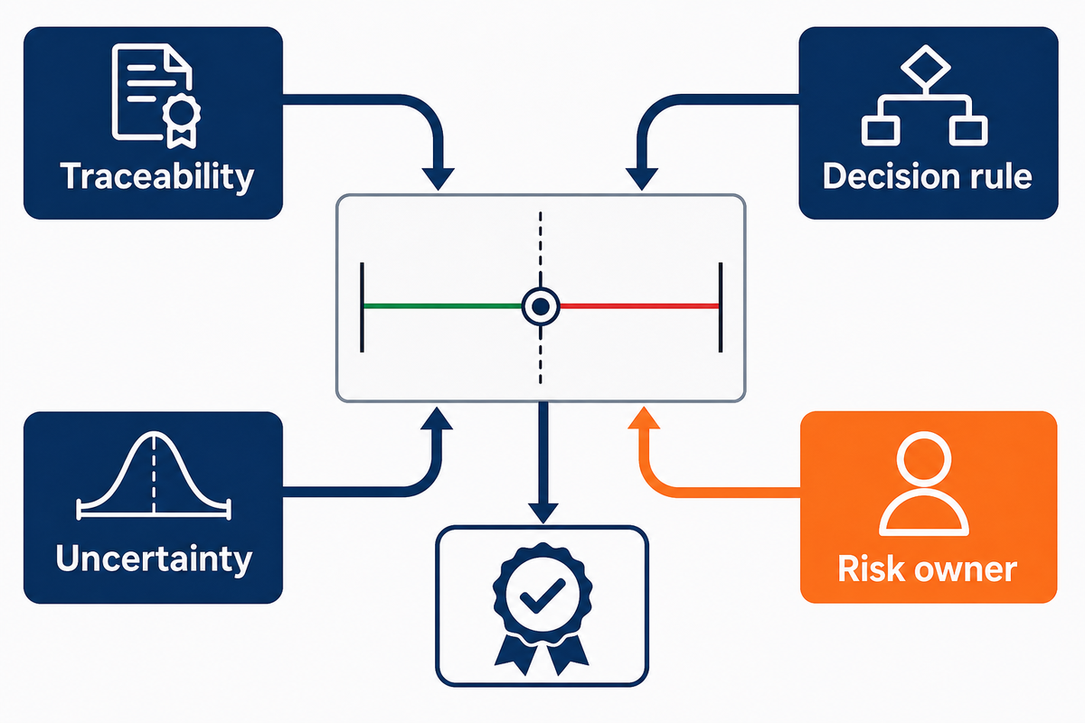
When traceability, uncertainty, and a decision rule are considered together, they support a conformity decision while serving different purposes. A calibration sticker or high display resolution doesn’t substitute for any of the three.
Traceability
Which references and calibrations support the result?
Which references and calibrations support the result?
Uncertainty
How much doubt is associated with the stated result?
How much doubt is associated with the stated result?
Decision rule
How does that evidence lead to accept, reject, or further review?
How does that evidence lead to accept, reject, or further review?
Uncertainty becomes evident when a result touches a spec limit. In such cases, the evidence may not support a conformity judgment, and uncertainty shouldn’t be addressed by rounding digits. If uncertainty isn’t addressed, the result and evidence should be provided to the decision owner.
Conceptual boundary view, not to scale
OutsideSpecified zoneOutside
Results near either edge need their uncertainty and decision rule; the line alone isn’t the whole evidence packet.
NIST’s conformity-decision work explains that rule selection balances false-accept and false-reject risks. Those consequences are rarely symmetrical, so the appropriate rule is also a business and contractual decision that belongs to an identified owner.
| Question | Why it matters |
|---|---|
| Which specification and revision control the limit? | A correct result cannot repair the wrong requirement. |
| What uncertainty applies to this result and state? | Instrument resolution alone is insufficient. |
| Which decision rule was agreed? | Different rules allocate risk differently. |
| Who owns the false-accept and false-reject consequences? | Metrology cannot silently choose the commercial risk. |
Place Measurement Across CNC Production Without Mixing Purposes
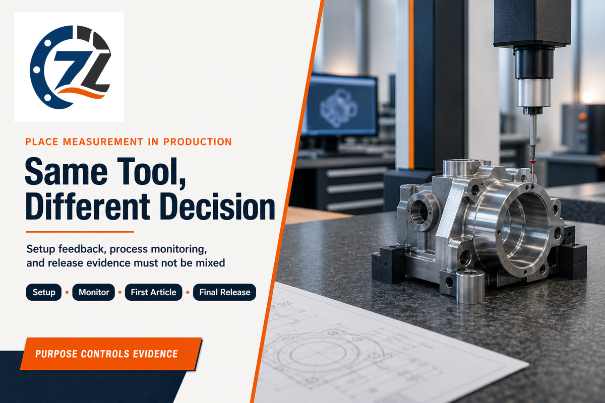
Measurement belongs at several points in CNC production, but each stage needs its own question, owner, and evidence status. It’s appropriate to conduct measurement checks for process control, but that purpose doesn’t automatically make them final-acceptance evidence.
| Stage | Primary question | Evidence status | Typical owner |
|---|---|---|---|
| Setup confirmation | Is the workpiece and tool relationship ready to run? | Setup control | Machining team |
| In-process control | Is the process remaining within its control plan? | Trend or correction input | Production and quality |
| First-article verification | Does the defined production realization satisfy the required verification scope? | Formal verification packet | Quality authority |
| Final acceptance | May the product be released under the applicable rule? | Release evidence | Named acceptance owner |
The same probe can appear more than once in a process. When it does, the frequency, independence, handling of uncertainty, and the outcome of the assessment may vary. Make certain to capture all of these variations.
Purpose label
Every result should say whether it is for setup, monitoring, investigation, first-article verification, or release. If more than one purpose is intended, each use needs an explicit procedure and owner.
Every result should say whether it is for setup, monitoring, investigation, first-article verification, or release. If more than one purpose is intended, each use needs an explicit procedure and owner.
In some customer and organizational systems, the terms ‘first article’ and ‘first piece’ aren’t interchangeable. This guide intentionally identifies differences at the purpose level and leaves the details to controlling quality documents.
Release boundary
Convenience, proximity, or automation does not decide evidence status. The approved measurement process and decision authority do.
Convenience, proximity, or automation does not decide evidence status. The approved measurement process and decision authority do.
Read Reports as Evidence, Not Just Numbers
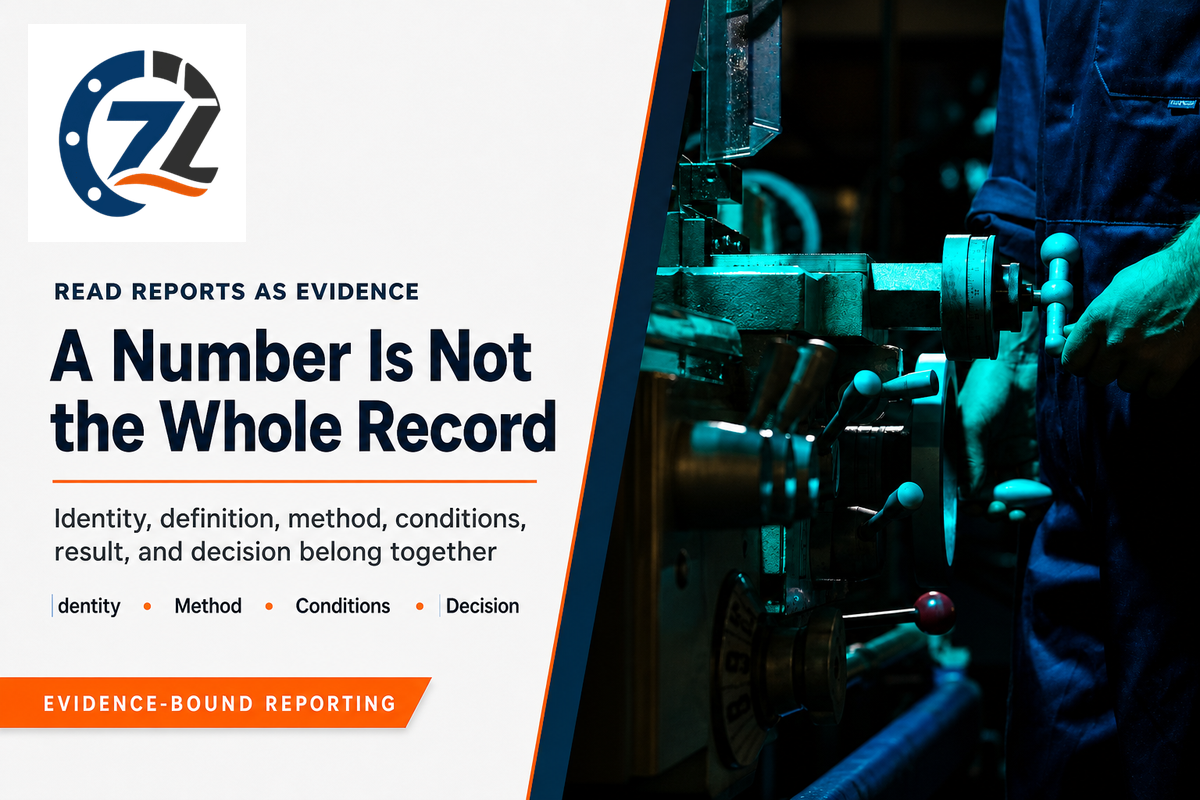
Results from an inspection review show that a reported high or low value may vary with the method and the measurement conditions. It’s also important for the report to identify the reviewer and sampling method used.
Educational report anatomy
- Identity: part number, serial/lot where applicable, drawing and revision.
- Definition: characteristic, units, nominal, tolerance, datum/alignment, and part state.
- Method: procedure, equipment reference, setup, sampling strategy, and fitted-feature method where relevant.
- Conditions: environmental or stabilization information needed to interpret the result.
- Result: actual value or attribute outcome, with uncertainty handling when required.
- Decision: rule, status, reviewer, date, and any escalation or concession reference.
| Data type | Syntax example | What a real report must also define |
|---|---|---|
| Measured size | 25.000 mm; 0.001 mm resolution; 100 mm range | Characteristic, method, and applicable uncertainty |
| Illustrative limits | 24.990 mm to 25.010 mm | Controlled source of the limits |
| Deviation | +0.004 mm against +0.010 mm example boundary | Sign convention and decision rule |
| Profile notation | 0.050 mm over a 25 mm region | Datum, evaluation zone, and fitting method |
| Surface notation | 1.6 µm with 0.8 mm cutoff and 4 mm trace length | Parameter, filter, instrument, and direction |
| Reference temperature | 20.0 °C with 0.1 °C logging resolution | Actual conditions and correction policy |
| Observed temperature | 23.0 °C, which is +3.0 °C from the example reference | Part temperature, gradients, material, and time |
| Stabilization record | 30 min before check; review again after 2 hr | Approved procedure and evidence of equilibrium |
| Sampling notation | 0.5 mm point spacing over a 25 mm path | Feature coverage, exclusions, and algorithm |
| Angle notation | 90.000° result with 0.050° example resolution | Axis/plane definition and uncertainty |
| Process context | 800 rpm recorded; check after 60 sec | Machine state and why the value matters |
| Review interval | Every 2 hr for 3 days | Control-plan owner and change rule |
Notation warning
The numbers above demonstrate how units and context can travel together; they are not Zhenling capabilities, product tolerances, sampling rules, or recommended acceptance criteria.
The numbers above demonstrate how units and context can travel together; they are not Zhenling capabilities, product tolerances, sampling rules, or recommended acceptance criteria.
Numeric data is more flexible and provides trend data. Attribute data, on the other hand, doesn’t allow for the same flexibility.
Value-only row
“Feature 12: 24.998 mm, Pass”
“Feature 12: 24.998 mm, Pass”
Missing: revision, tolerance, datum, state, method, uncertainty handling, and decision rule.
Evidence-bound row
Links the value to the controlled definition, method identity, relevant conditions, and release logic.
Links the value to the controlled definition, method identity, relevant conditions, and release logic.
This is an educational pattern, not a universal Zhenling report format.
When computing geometric tolerances, variation can arise from one method or instrument to another, so reports may need the point distribution, filtering, association, and software method.
Reading rule
Do not ask only whether the report says “pass.” Ask whether the report contains enough controlled context to support the decision you intend to make.
Do not ask only whether the report says “pass.” Ask whether the report contains enough controlled context to support the decision you intend to make.
Use Measurement Feedback Without Chasing Noise

Outliers may occur in measurements, but one anomalous result shouldn’t automatically change a CNC offset. Anomalous measurements may occur for numerous reasons including variation in the part, measurement setup, sampling, method of fitting, and the environment.
The 5-Gate Offset Change Rule
1. Verify identity
Part, feature, program, tool, revision, and units
Part, feature, program, tool, revision, and units
2. Repeat or cross-check
Use the controlled method and defined repeat rule
Use the controlled method and defined repeat rule
3. Inspect conditions
Setup, support, surface, temperature, and sensor
Setup, support, surface, temperature, and sensor
4. Compare stability
Operators, configurations, time, and prior trend
Operators, configurations, time, and prior trend
5. Authorize correction
Only the named owner changes the process
Only the named owner changes the process
Changes require information from a measurement process that’s stable enough to serve as a basis for the desired determination. If relevant drifts, for example, due to the operation of the equipment or changes in the adjustment of the equipment, haven’t been taken into account, an observed difference over time may be due to the measurement process.
Stop path
When the second result does not reproduce the first, investigate measurement identity and conditions before calculating a correction. When it does reproduce, compare the pattern with tool wear, thermal behavior, fixture condition, and other process evidence before acting.
When the second result does not reproduce the first, investigate measurement identity and conditions before calculating a correction. When it does reproduce, compare the pattern with tool wear, thermal behavior, fixture condition, and other process evidence before acting.
Nonetheless, correction systems require specification of measurement process behavior, constraints, and limits. Such systems should be designed to take corrective action.
Do not chase the last value
The goal is a controlled process, not constant reaction. Change offsets when evidence shows a process correction is justified, not merely because a number differs from the previous number.
The goal is a controlled process, not constant reaction. Change offsets when evidence shows a process correction is justified, not merely because a number differs from the previous number.
Decision Framework: Learn, Escalate or Request Service
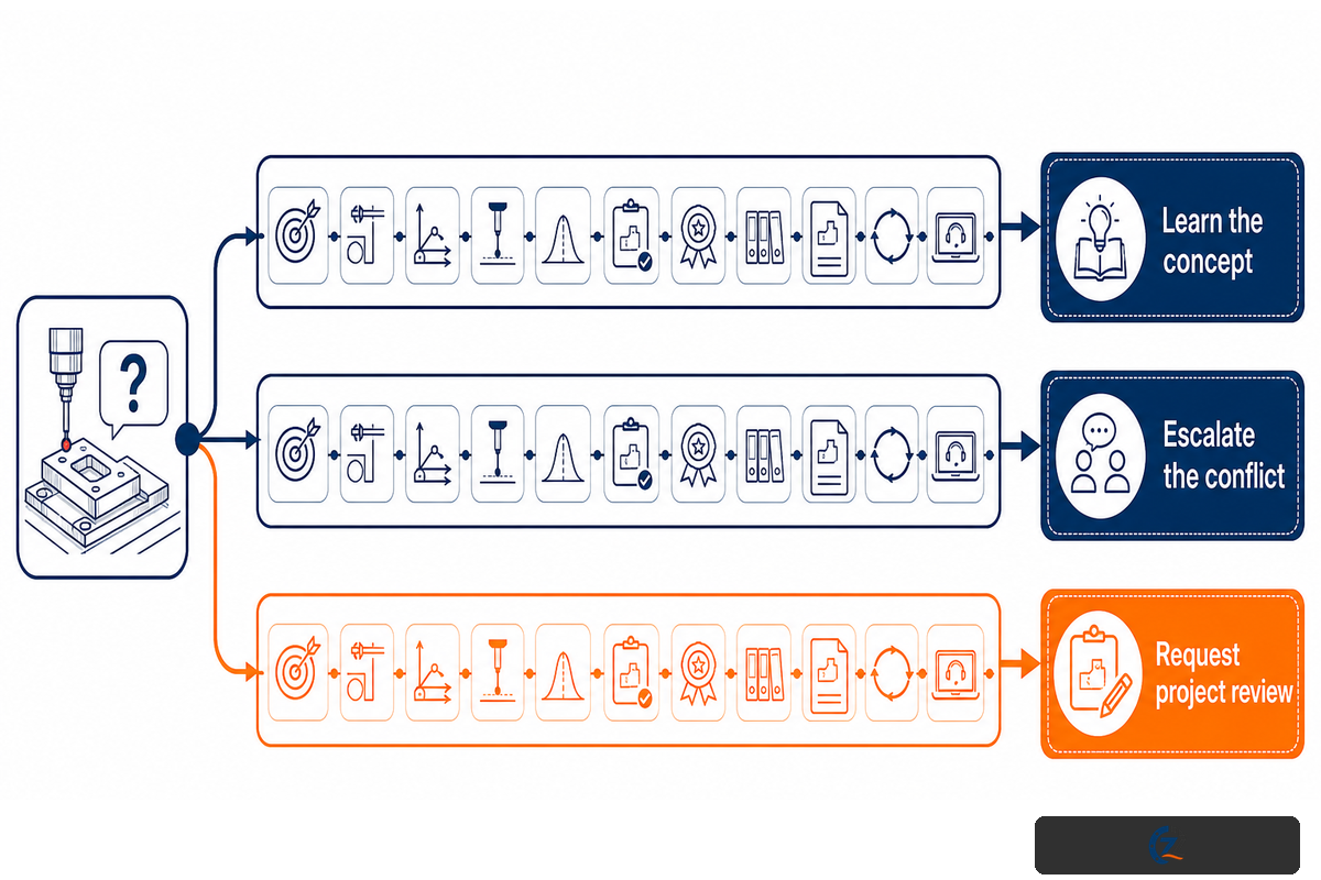
Use this guide to understand the terminology and logic behind the methods described here. Report any doubts you may have to qualified personnel, and take a released drawing to the CNC metrology service page for scope review.
| Need | Correct owner | Next evidence |
|---|---|---|
| Understand a concept | This guide and cited authorities | Definition and boundary |
| Resolve datum, state, method capability, or near-limit conflict | Responsible design/quality/metrology authority | Controlled requirement and reviewed decision |
| Plan inspection for a real drawing and part | Qualified service and project team | Drawing, feature list, state, quantity, purpose, and reporting scope |
For inspection scope, component and drawings, use Zhenling’s (CNC metrology) service planning and execution site. Capability, report scope, quotation and execution for the service described on the site are provided. This literature, however, provides no information regarding the unstated method, tolerance, price, lead time, or the end outcome.
Bring a defined measurement question
Share the released drawing, characteristics, datum scheme, part state, quantity, decision purpose, and required report context. Zhenling can review the inspection scope without replacing the drawing owner or acceptance authority.
Frequently Asked Questions
What is CNC metrology?
CNC metrology is the controlled measurement system used around CNC machining to verify parts, understand process behavior, check machine-tool condition, and preserve the evidence needed for a defined decision.
It includes more than the measuring instrument: the drawing revision, characteristic, datum, part state, environment, method, reference chain, uncertainty, result, decision rule, and evidence record all matter. A CMM can be part of that system, but it does not define the whole discipline or automatically make every result suitable for release.
Can a CNC machine measure parts like a CMM?
An on-machine probe can locate workpieces, check selected features, and support process feedback, but it is not automatically equivalent to an independently characterized CMM for final acceptance.
The machine, probe, thermal state, calibration, probing strategy, sampling and fitting method, uncertainty, and decision purpose determine what the result can support. Final acceptance may be possible under an approved process, but it cannot be inferred from the presence of a probe or from a successful setup cycle. The responsible team must also establish repeatability, reproducibility, long-term stability, and the relationship between machine conditions and the contractual part state. Independent measurement may still be required when the control plan, customer specification, or risk allocation calls for it.
Which measuring tools are used in CNC machining?
Common routes include hand tools, fixed gauges, indicators, height and surface instruments, CMMs, optical systems, scanners, and on-machine probes selected by feature, tolerance, access, and evidence need.
The right choice depends on feature geometry, access, tolerance, surface, environment, required output, uncertainty, and decision. Simpler calibrated tools may suit accessible sizes, while complex geometric relationships may need coordinate or optical measurement; neither option is universally superior. Method selection should also consider point sampling, fitted geometry, operator influence, stabilization, report needs, and whether the result supports setup, process control, investigation, or final acceptance. Compare those criteria before comparing brands or automation levels.
What should a CNC inspection report include?
A useful report identifies the part, drawing revision, units, characteristic, nominal and tolerance, datum/alignment, method, actual result, inspection stage, decision status, relevant conditions, and uncertainty handling.
For critical, computed, or near-limit characteristics, the contract may also require environmental context, uncertainty handling, decision rule, point-sampling or fitting details, raw data, or an approval record. Report content must match the acceptance purpose rather than follow a universal template.
Why can two correct measurements differ?
Differences can come from datum realization, alignment, sensor choice, point distribution, filtering, fitted geometry, fixture force, temperature, surface condition, operator, configuration, and ordinary repeatability under correct process control.
Differences are not automatically proof that one result is wrong. First compare the same drawing revision, characteristic definition, state, setup, conditions, method, computation, uncertainty handling, and decision purpose; then investigate measurement-system stability and process causes.
Editorial note
The Measurement Question Chain, Method Fit Compass, Measurement Confidence Stack, and Offset Change Firewall are editorial frameworks created for this guide. They are not NIST, ISO, NPL, customer, or Zhenling inspection procedures.
The Measurement Question Chain, Method Fit Compass, Measurement Confidence Stack, and Offset Change Firewall are editorial frameworks created for this guide. They are not NIST, ISO, NPL, customer, or Zhenling inspection procedures.
References & Sources
- A Rule Model for Selecting Dimensional Measurement Equipment in Inspection Planning National Institute of Standards and Technology
- NISTIR 5170: Evaluation of Coordinate Measuring Machine Task Specific Measurement Uncertainty NIST
- What Is the Difference Between Accuracy and Uncertainty? National Physical Laboratory
- ISO 1:2022, Geometrical Product Specifications: Standard Reference Temperature International Organization for Standardization
- The 20 °C Reference Temperature for Industrial Dimensional Measurements NIST authors via PubMed Central
- Assessment of Conformity: Decision Rules and Risk Analysis NIST
- Gauge R&R Studies NIST/SEMATECH Engineering Statistics Handbook
- Coordinate Metrology Algorithm Testing NIST
- Probing and Tool Measurement Systems for Machine Tools Renishaw
Sources accessed September 29, 2026.