GD&T inspection checks a part’s conformance to the geometric requirements on the drawing with an appropriate datum setup, measurement method, and evaluation. Reports are useful when each result is linked to a specific characteristic and its limits. The type of measurement equipment affects the outcome, so a usable report also names the setup and evaluation behind each result.
A Quality Engineer must have an adequate basis for accepting a part while a Manufacturing Lead who must inspect a failed part needs to understand the evidence well enough to determine if there’s a basis to reopen a machining operation or the Fixture and/or measurement setup. Procurement needs to know which deliverables a quotation includes. Follow one feature on the engineering drawing and its requirement through the measurement record to answer the question posed by the measurement record and the part, prior to extending the plan to the overall part.
Read the GD&T requirement and ASME Y14.5 edition
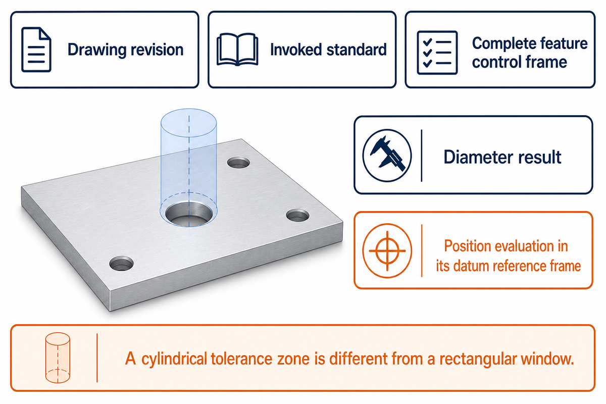
A GD&T requirement needs to be interpreted in conjunction with the drawing revision, invoked standard and complete feature control frame. Size, geometric control and datum references answer different questions about the part. Recording those questions separately prevents an adequate diameter measurement from being confused with evidence that a hole is properly located.
ASME’s Y14.5 catalog lists the ASME Y14.5-2018 standard, reaffirmed in 2024. The edition invoked by the drawing remains the starting point. An ISO specification needs its own applicable interpretation; choosing ISO or ASME settings in software is not a substitute for resolving that requirement.
What is a feature control frame?
A feature control frame identifies the geometric characteristics, tolerance and applicable modifiers, with datum references where required. Read it in conjunction with the controlled feature and basic dimensions. Those theoretically exact dimensions define the intended geometry; they aren’t separate bands to be added to the geometric tolerance.
For a hypothetical hole, distinguish the diameter result from the position evaluation in its datum reference frame. A cylindrical tolerance zone is different from a rectangular window made from linear dimensions. Prior to interpreting GD&T callouts, you must be able to identify the symbols used on the drawing and determine what each observation represents. Special instructions such as a projected tolerance zone or continuous feature symbol require explicit treatment in the inspection plan.
Establish the datum reference frame before inspection
Datum setup is the method through which the references are established against which the specified geometries are assessed. A datum feature is the actual part feature, and the datum is the ideal reference derived from it. CMM fixturing can’t replace the required precedence, because a different reference frame can change the reported relationship between otherwise unchanged features.
The ASME inspection and reporting course explicitly addresses datum precedence and contact simulation with hard gages. Have the inspector identify the simulator or computational construction used. If the alignment is unclear, trace errors in datum setup before commissioning another measurement run.
What is the 3/2/1 rule for GD&T?
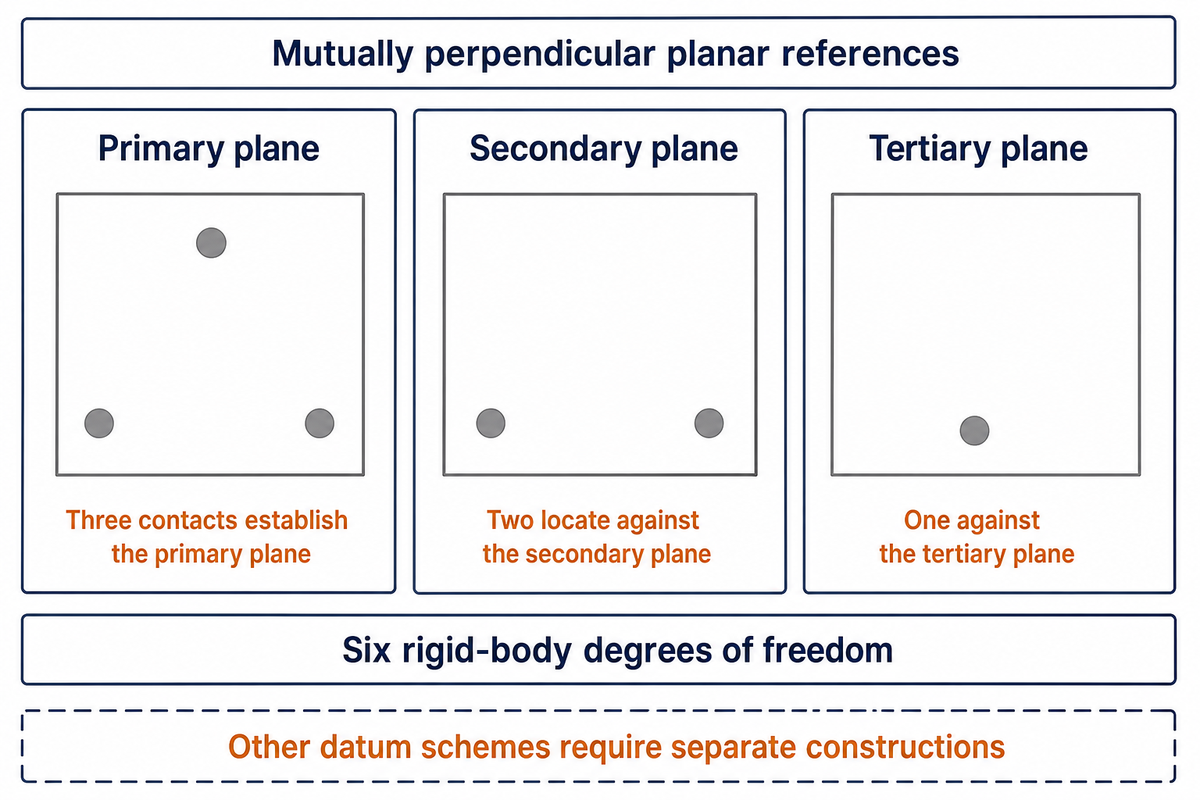
The 3/2/1 rule is a locating illustration for mutually perpendicular planar references: three contacts establish the primary plane, two locate against the secondary plane, and one against the tertiary plane. In this bounded arrangement, the contacts constrain six rigid-body degrees of freedom. Other datum schemes require separate constructions.
A cylindrical datum or an unconstrained movement doesn’t become a three-plane setup merely because a fixture has six contacts. Attention must be paid to the type of clamping: a flexible bracket can change shape under a restraining force. Record the contact locations and determine the part’s inspection state. If the purchase specification leaves that state unresolved, it should be resolved before treating two suppliers’ results as comparable.
Match CMM inspection and other methods to the tolerance zone
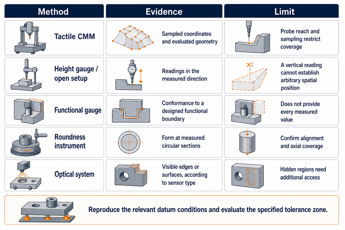
CMM methods (inspection) or manual methods should be used, based on the available characteristic and accessible geometry and the requirement of the output. A method must reproduce the relevant datum conditions and evaluate the specified tolerance zone. A functional check may answer a conformance question, leaving the numerical deviations needed for manufacturing diagnosis unreported.
The ASME Y14.45 measurement data reporting standard covers attribute and variable data independently of the equipment used. That distinction helps separate a go/no-go requirement from a request to measure and report individual values. It doesn’t make all instruments interchangeable.
| Method | Useful evidence | Limit and next check |
|---|---|---|
| Tactile CMM | Sampled coordinates and evaluated geometry, including accessible hole patterns. | Probe reach and sampling restrict coverage. Verify datum construction and evaluation settings. |
| Height gauge / open setup | Readings in the measured direction under a defined setup. | A vertical reading cannot establish arbitrary spatial position. Check which relationship the setup isolates. |
| Functional gauge | Conformance to a designed functional boundary. | Does not provide every measured value. Verify gauge design, modifiers and datum simulation. |
| Roundness instrument | Form at measured circular sections under its evaluation method. | Roundness and datum-referenced runout are different controls. Confirm alignment and axial coverage. |
| Optical system | Visible edges or surfaces, according to sensor type. | Hidden regions need additional access. Review surface condition and any registered views. |
To determine what’s needed for a hole pattern, ask if the required deliverable is assembly-boundary conformance, individual location values, or both, since a buyer who needs to diagnose which hole is displaced can’t assume that a boundary check will provide the missing coordinates. Maximum material condition (MMC) and least material condition influence the applicable interpretation where specified. It’s a shortcut to presume that every (MMC) callout provides a fixed gauge; the design must address the specific requirement.
Coordinate measuring machines can evaluate multiple dimensions in one program, but the program still needs characteristic-specific checks. Perpendicularity, parallelism and angularity involve orientation; flatness is form control. Check that the selected calculation matches the design intent rather than trusting the software label.
Use a height gauge only with a suitable setup
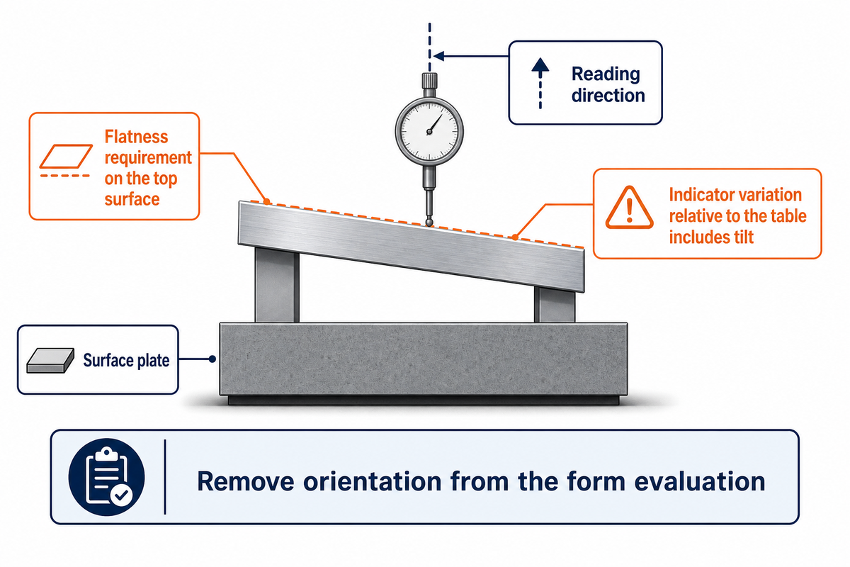
A height gauge can support manual inspection when the setup isolates the required relationship and the contact can reach the surface. A surface plate provides a reference for the reading direction. A sweep across a part resting on its opposite face can include effects of that face’s orientation.
Suppose we have a plate with a flatness requirement on the top surface. If the support tilts that surface, indicator variation relative to the table includes tilt. Thinking of variation as flatness without the right setup and evaluation can lead to the wrong conclusion. Describe how you’ll remove orientation from the form evaluation.
This applies to both Hand tools and digital equipment. The ASME course’s coverage of open-setup inspection places the method within geometric interpretation. For a disputed result, obtain the description of the setup and the direction that was measured before swapping the instrument. A finer display alone does not correct a mismatched check.
Check optical metrology access and surface coverage
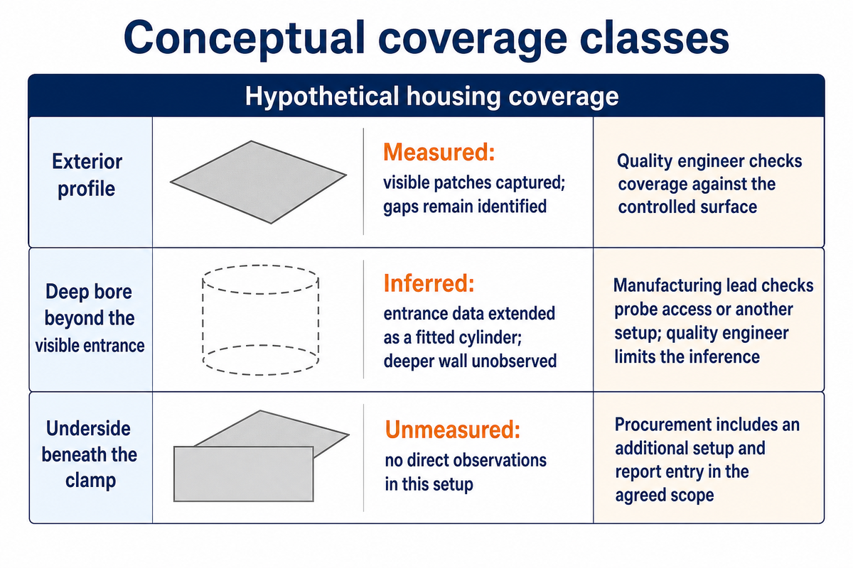
Optical metrology records accessible geometry. A dense point cloud doesn’t mean that hidden surfaces have been measured. Distinguish direct observations from assumptions and coverage gaps. Each distinction changes the next action: validate the evaluation, obtain another view, or add a method that can reach the omitted region.
The Optical Coordinate Metrology review describes the limitations of line of sight and the need for multiple measurement positions. Registration is required for additional views. A tactile probe also requires access, so a deep bore can’t be assigned solely from its name to a particular method.
| Feature / evidence | Coverage status | Owner and action |
|---|---|---|
| Exterior profile | Measured: visible patches captured; gaps remain identified. | Quality engineer checks coverage against the controlled surface. |
| Deep bore beyond the visible entrance | Inferred: entrance data extended as a fitted cylinder; deeper wall unobserved. | Manufacturing lead checks probe access or another setup; quality engineer limits the inference. |
| Underside beneath the clamp | Unmeasured: no direct observations in this setup. | Procurement includes an additional setup and report entry in the agreed scope. |
Use these coverage labels for a defined region, rather than as a quality rating for the entire part. An inferred bore extension can’t be presumed to be measured coverage, even when the software shows a continuous cylinder whose visible entrance agrees with the CAD model, because the display supplies no new observations of the hidden wall. To choose a second method, compare contact and optical methods against the missing region and the evaluation that’s required.
NIST’s 2019 structured-light study explains that application conditions can differ from instrument test conditions. Request evidence relevant to the part surface and viewing conditions, rather than assuming a test artifact specification applies unchanged.
Treat metrology calibration as one part of measurement evidence
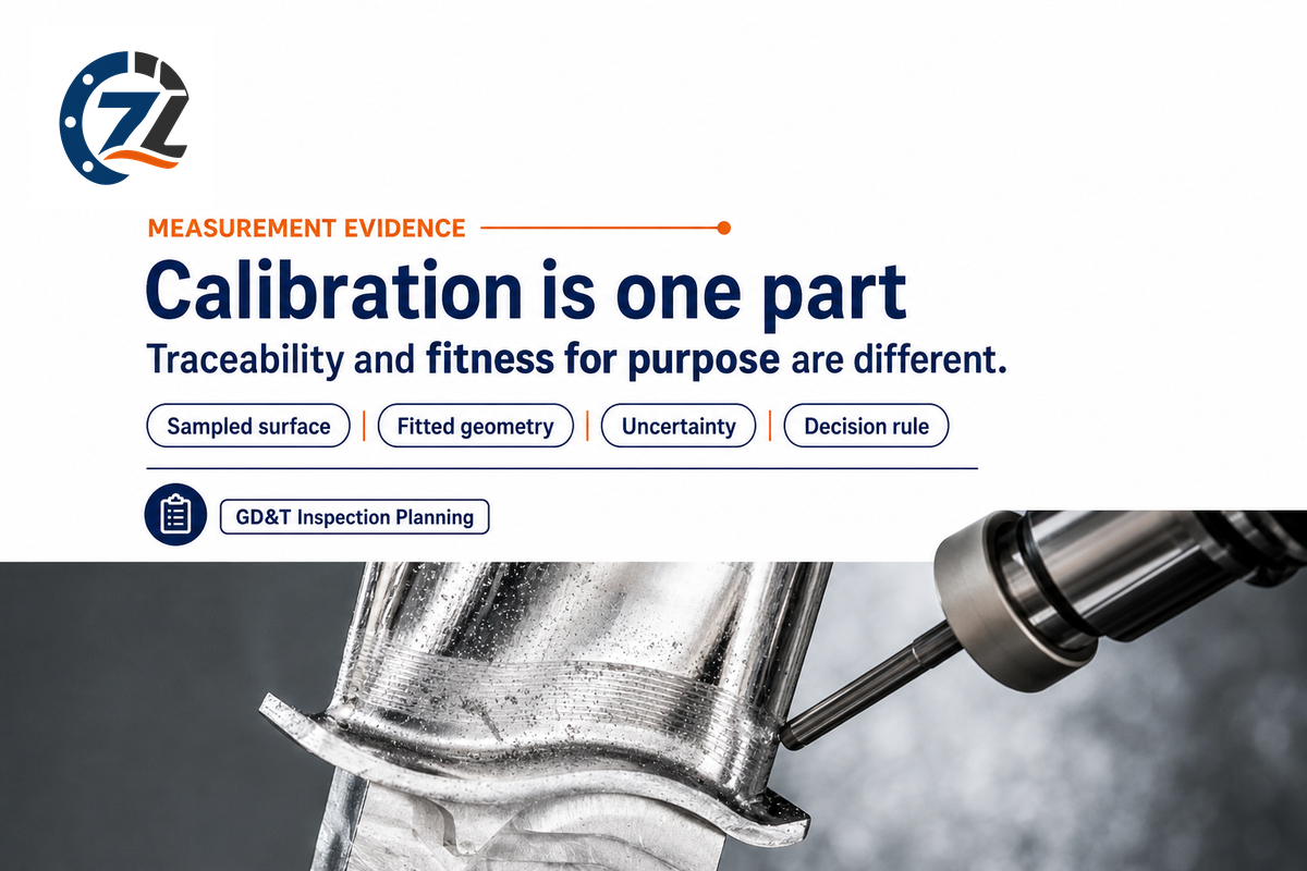
Calibration covers the instrument, one part of measurement evidence; fitness for a particular tolerance decision is a separate check on the result. Ask how uncertainty applies to the reported result and which decision rule governs acceptance or rejection, especially near a tolerance limit.
“Only measurement results can be traceable.”
NIST also states that traceability and fitness for purpose are different. A calibration for a device (measurement equipment) doesn’t answer all the questions related to a measurement (inspection) result. For fitness for purpose, the appropriate uncertainty assessment should be provided instead of assuming a universal resolution-to-tolerance ratio.
NIST’s 2013 coordinate-metrology paper separates two questions: whether sampled points represent the surface, and whether the fitted geometry meets criteria consistent with the specification. Adding points does not fix an unsuitable evaluation, and least-squares fitting is acceptable when the fitted geometry meets those criteria.
ASME B89.7.3.1 addresses decision rules that consider measurement uncertainty. State the applicable rule without using a universal guard band. Use the method details to assess uncertainty near the tolerance limit and to investigate differing CMM results before deciding that either supplier measured incorrectly.
Read geometric tolerance results as inspection evidence
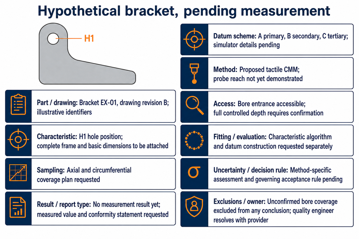
A tolerance result becomes useful evidence when a reader can trace it to the requirement, setup and evaluation. A pass stamp leaves the relationships between those elements unclear. Provide a characteristic identifier and measurement details, and distinguish the acceptance statement from additional data needed to diagnose the manufacturing process.
The ASME course on quality inspection and reporting describes Method A conformance, Method B measured values and Method C supplemental data under ASME Y14.45-2021. This course description is available to the public and is not a reproduction of the standard. Use it to distinguish attribute and variable results when agreeing deliverables.
| Record field | Filled example and unresolved item |
|---|---|
| Part / drawing | Bracket EX-01, drawing revision B; illustrative identifiers. |
| Characteristic | H1 hole position; complete frame and basic dimensions to be attached. |
| Datum scheme | A primary, B secondary, C tertiary; simulator details pending. |
| Method | Proposed tactile CMM; probe reach not yet demonstrated. |
| Access | Bore entrance accessible; full controlled depth requires confirmation. |
| Sampling | Axial and circumferential coverage plan requested. |
| Fitting / evaluation | Characteristic algorithm and datum construction requested separately. |
| Result / report type | No measurement result yet; measured value and conformity statement requested. |
| Uncertainty / decision rule | Method-specific assessment and governing acceptance rule pending. |
| Exclusions / owner | Unconfirmed bore coverage excluded from any conclusion; quality engineer resolves with provider. |
The record deliberately leaves the result unstated. A machinist can request location information for a diagnosis while quality control requests conformity evidence. The provider needs both requests to decide which report to give. That report could otherwise contain only a pass stamp and no feature-level information to aid in a correction. Neither request justifies filling a missing measurement with a nominal CAD value.
Define the scope of CMM inspection services before comparing quotes

Comparable quotes for CMM inspection services cover the same characteristics, quantities and deliverables. Distinguish between programming and fixture preparation and per-part measurement and reporting. Otherwise, a lower quoted rate may describe less work, with access checks or diagnostic data left for a later order.
A2LA’s 2025 article from here talks about communications issues resulting from vaguely defined service requests. The example provided is a calibration procurement example. For CMM work, one dimensional-inspection lab publishes an hourly service rate of $70/hr and quotes all jobs in advance. The following inspection scope grid, an editorial application of the communication lesson, is provided with no market prices.
| Scope | Ask each provider to state |
|---|---|
| Preparation | Drawing/model revision, programming and fixture work included. |
| Measurement | Part quantity, selected characteristics, sample extent and additional setups. |
| Deliverables | Report format, measured values, conformity rule and requested diagnostic data. |
| Changes | Treatment of revision changes, inaccessible features and remeasurement. |
During procurement, an incomplete quote, with the missing row identified, can be returned, and the service provider may be asked if the work described in the missing row is included, excluded, or is subject to a set-up review. The manufacturing lead resolves access assumptions; the quality engineer agrees the evidence needed. Neither full-part inspection nor a particular reporting depth should be assumed when the order specifies a narrower sample.
Build a one-feature inspection record for handoff

A one-feature handoff should allow another reader to follow the requirement through setup, sampled geometry, and reported results. Attach the appropriate drawing detail and solicit a sample of the output before expanding the plan. In the absence of access or evaluation fields, a named owner should be specified; an automated report can’t make observations if the data haven’t been collected.
The public scope of ASME Y14.45-2021 provides a reporting reference, but the One-Feature Inspection Record is an editorial aid, not a mandatory ASME form. Record the reporting edition required by the order. Don’t replace it merely because software has a newer template.
Once the quality engineer resolves the bracket example’s open fields, procurement can take the committed deliverables into the order, including any additional setup for bore access and the report fields that manufacturing will use if the feature fails to satisfy the requirement. Manufacturing retains the access and fixturing assumptions. If the drawing or the part changes, re-evaluate the affected record before reusing the measurement program. For a more extensive measurement program, consult the CNC metrology and inspection Library.
FAQs: GD&T inspection questions
What does GD&T stand for?
GD&T stands for geometric dimensioning and tolerancing.
It communicates requirements for part geometry and permitted variation through engineering drawing conventions. Inspection of GD&T connects those requirements to evidence about the produced part. A size check can be part of that evidence, but the required form, orientation or location evaluation still needs its own appropriate method and interpretation.
Which ASME standard covers GD&T?
ASME Y14.5 covers dimensioning and tolerancing.
The American Society of Mechanical Engineers lists Y14.5-2018, reaffirmed in 2024, in its public catalog. Use the edition invoked by the drawing and applicable purchase order. ASME standards addressing measurement reporting or decision rules answer related questions; neither a reporting format nor an equipment calibration replaces the drawing’s geometric requirements.
What is a GD&T drawing?
A GD&T drawing uses geometric controls to specify permitted variation in a part.
Read its dimensions and tolerances with the notes, revision and applicable standard. Basic dimensions and datum references give context to the control symbols. Engineers and manufacturers need the complete requirement before choosing an inspection method; an isolated symbol or cropped screenshot can omit information that changes how the feature must be evaluated.
What are 14 symbols in GD&T?
Older charts of 14 symbols include concentricity and symmetry, which ASME Y14.5 eliminated when it was last updated in 2018.
GD&T symbols describe controls such as roundness and profile of a line. Do not assume an older teaching chart matches every drawing. Identify the invoked edition before applying its terminology.
What is rule 2 of GD&T?
Rule 2 makes regardless of feature size (RFS) the default for any geometric tolerance on a feature of size in ASME GD&T; MMC or LMC applies only where the drawing calls it out.
For a feature of size, distinguish the geometric-tolerance default from the material-boundary default for a datum reference. Maximum material terminology in those two locations has different effects on inspection. Read the modifier in its actual location and check the edition’s applicable rules and exceptions. “Unless otherwise specified” is not permission to apply one shortcut to every feature control frame.
Is GD&T hard to learn?
GD&T is easier to learn through complete feature examples than isolated symbols.
Start with GD&T basics, connect each requirement to its measurement evidence, then study advanced GD&T applications. Knowing a symbol does not establish that a particular gaging setup evaluates it correctly.
Can an inspection report confirm surfaces that were not measured?
No. A report can label unobserved surfaces only as inferred or unmeasured, never as measured.
A justified inference may support a defined conclusion, but its assumptions and limits must remain visible. Mark missing regions, explain any fitted extension and state what additional measurement is required. A smooth CAD comparison or dense visible point cloud does not fill a hidden bore. Ask whether the omitted region can deviate in a way the current observations would fail to reveal before accepting that inference.
Bring one feature to the machining discussion
Choose the feature whose inspection evidence is least clear. Attach its drawing revision and use the open fields in the record to prepare inspection evidence for a machining inquiry with Zhenling Metal. That gives the discussion a specific requirement and a visible list of unresolved measurements.
About this technical guide
This educational guide is published by Shanghai Zhenling Hardware Co., Ltd. (Zhenling Metal). It draws on public standards descriptions and metrology publications. The coverage map and bracket record are hypothetical planning examples, not customer inspection results or evidence of a particular machine’s capability.
References & Sources
- ASME: Y14.5 Dimensioning and Tolerancing, 2018 (R2024).
- ASME: Geometric Dimensioning and Tolerancing Quality Inspection and Reporting course.
- ASME: Y14.45-2021 Measurement Data Reporting.
- NIST: Metrological Traceability, FAQ 5.1.5 and fitness-for-purpose discussion.
- NIST: On the Enduring Appeal of Least-squares Fitting in Computational Coordinate Metrology, 2013.
- NIST: Sources of Errors in Structured Light 3D Scanners, 2019.
- ASME: B89.7.3.1, Decision Rules Considering Measurement Uncertainty.
- The International Journal of Advanced Manufacturing Technology: optical coordinate metrology review, section 3.2.
- A2LA: Laboratories & Calibration Providers: Let’s Talk, July 2025.