By XCX | Reviewed by the Shanghai Zhenling Hardware Co., Ltd. technical team | (Updated October 2026)
The iron melting point is approximately 1,538 °C (2,800 degrees Fahrenheit or 1,811 K) for pure elemental iron (Fe) at 1 atm, as recorded in Wikipedia’s Iron reference. Commercial ferrous alloys don’t melt at a single temperature. The carbon steels tabulated below melt between 1,355 and 1,525 °C, while austenitic stainless steels melt between 1,375 and 1,450 °C. Gray and ductile cast irons melt between roughly 1,120 and 1,250 °C under NIST phase equilibrium definitions.
Direct Engineering Answer: Pure iron melts and freezes at approximately 1,538 °C (2,800 °F / 1,811 K) at 101.325 kPa. Alloying creates a solidus-to-liquidus interval: roughly 1,480-1,525 °C for 1018 mild steel, 1,355-1,475 °C for 1095 high-carbon steel, 1,400-1,450 °C for 304 stainless, and 1,120-1,250 °C for cast iron.
Key Takeaways for Material Selection and Machining
- Elemental iron shifts through alpha-ferrite, gamma-austenite (912 °C), and delta-ferrite (1,394 °C) solid crystal lattices before melting at approximately 1,538 °C at 1 atm.
- The solidus marks equilibrium melting onset, though segregated grain boundaries can liquefy lower and practical heat-treatment ceilings sit lower still. Foundries superheat molten metal above liquidus to fill thin mold sections.
- Type 304 stainless steel melts at 1,400 to 1,450 °C, 75 °C below the 1018 mild steel liquidus, even with the presence of chromium oxide which slows high temperature air scaling.
- Hot-rolled structural carbon steel loses strength near 300 °C and retains about 60% of room-temperature yield strength and 45% stiffness by 550 °C.
Quick Specs: Ferrous Melting and Thermal Reference
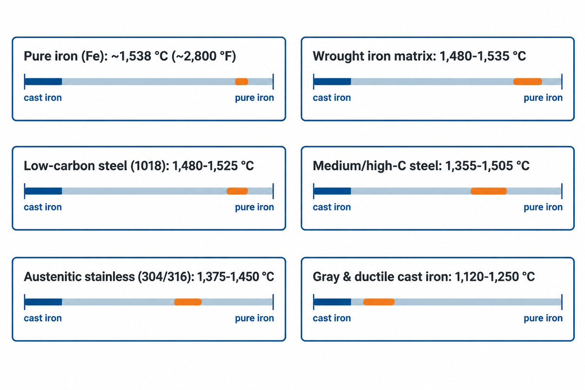
| Ferrous Material Family | Nominal Carbon (wt%) | Melting / Solidus-Liquidus (°C) | Melting / Solidus-Liquidus (°F) | Key Shop-Floor Note |
|---|---|---|---|---|
| Pure Elemental Iron (Fe) | <0.01 wt% | ~1,538 °C | ~2,800 °F | Approximately 1,811 K at 101.325 kPa |
| Wrought Iron (Slag-Bearing) | <0.08 wt% | 1,480-1,535 °C (matrix) | 2,696-2,795 °F (matrix) | Silicate slag stringers liquefy near ~1,200 °C |
| Low-Carbon Steel (AISI 1018) | 0.15-0.20 wt% | 1,480-1,525 °C | 2,696-2,777 °F | Narrow mushy zone; readily weldable |
| Medium/High-Carbon Steel (1045 / 1095) | 0.43-1.03 wt% | 1,355-1,505 °C | 2,471-2,741 °F | Wider freezing band; preheat required for welding |
| Austenitic Stainless (304 / 316) | ≤0.08 wt% | 1,375-1,450 °C | 2,507-2,642 °F | Cr and Ni lower liquidus vs mild steel |
| Gray & Ductile Cast Iron | 2.90-3.80 wt% | 1,120-1,250 °C | 2,048-2,282 °F | Near Fe-C-Si eutectic; low pouring temperature |
Pure Iron Melting Point, Units and Reference Conditions
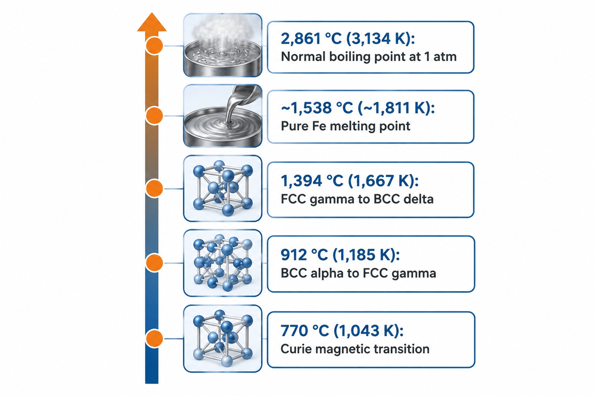
At 101.325 kPa (1 atm), pure elemental iron melts at approximately 1,538 °C (2,800 °F / 1,811 K) in Wikipedia’s elemental iron profile. Commercial steels melt lower across composition-dependent bands modeled by NIST solidification guidelines, while pure iron boils at 2,861 °C (5,182 °F / 3,134 K).
Older metallurgy handbooks sometimes print 1,535 °C or 1,539 °C. Two physical variables explain that 3-4 °C spread.
Trace oxygen, sulfur, or carbon impurities of 0.02-0.05 wt% depress the freezing threshold, and legacy temperature scales historically differed slightly compared to modern thermometry around 1,811 K. When engineering teams cross-check vacuum-furnace or brazing specs on our engineering material selection hub, stating metal purity and 1 atm pressure prevents sign-off delays. In high-vacuum induction chambers below 1 Pa, molten iron shifts its freezing point by less than 1 °C. However, manganese and copper alloying additions evaporate rapidly from the melt pool.
Before pure iron turns liquid, its solid crystalline lattice reorganizes twice during heating, as outlined in Britannica’s ferrous metallurgy overview. Room-temperature iron starts as magnetic body-centered cubic (BCC) alpha-ferrite and loses ferromagnetism at the 770 °C Curie point. At 912 °C (1,674 °F), alpha-iron transforms into denser face-centered cubic (FCC) gamma-iron (austenite). At 1,394 °C (2,541 °F), austenite reverts to BCC delta-ferrite, which absorbs 13.81 kJ/mol of fusion heat near 1,538 °C.
| Pure Fe Phase / Transition (1 atm) | Celsius (°C) | Fahrenheit (°F) | Kelvin (K) | Lattice / Physical State |
|---|---|---|---|---|
| Curie Magnetic Transition | 770 °C | 1,418 °F | 1,043 K | BCC alpha-iron becomes paramagnetic |
| Alpha (α) to Gamma (γ) | 912 °C | 1,674 °F | 1,185 K | Solid BCC ferrite shifts to FCC austenite |
| Gamma (γ) to Delta (δ) | 1,394 °C | 2,541 °F | 1,667 K | Solid FCC austenite reverts to BCC delta-ferrite |
| Equilibrium Melting / Freezing | ~1,538 °C | ~2,800 °F | ~1,811 K | BCC delta-ferrite liquefies (13.81 kJ/mol) |
| Normal Boiling Point | 2,861 °C | 5,182 °F | 3,134 K | Liquid iron vaporizes at 101.325 kPa |
What is the difference between melting and smelting?
Melting is a physical phase change from solid metallic iron or steel to liquid, without changing its oxidation state, above 1,120 to 1,538 °C. Smelting, a chemical reduction process, occurs in a blast furnace or plasma vessel, modeled in U.S. DOE Princeton Plasma Physics Laboratory research. Inside, oxygen atoms are stripped from the iron oxide ore to yield metallic iron.
Why Ferrous Alloys Melt Over a Solidus-to-Liquidus Range
Cast iron melts roughly 290-420 °C lower than pure iron. Dissolved carbon and silicon shift the alloy toward the Fe-C eutectic composition at 4.3 wt% C documented by Cambridge University’s DoITPoMS, which melts near 1,147 °C (2,097 °F). Multi-component ferrous alloys therefore melt across a two-phase solidus-to-liquidus interval rather than one temperature.
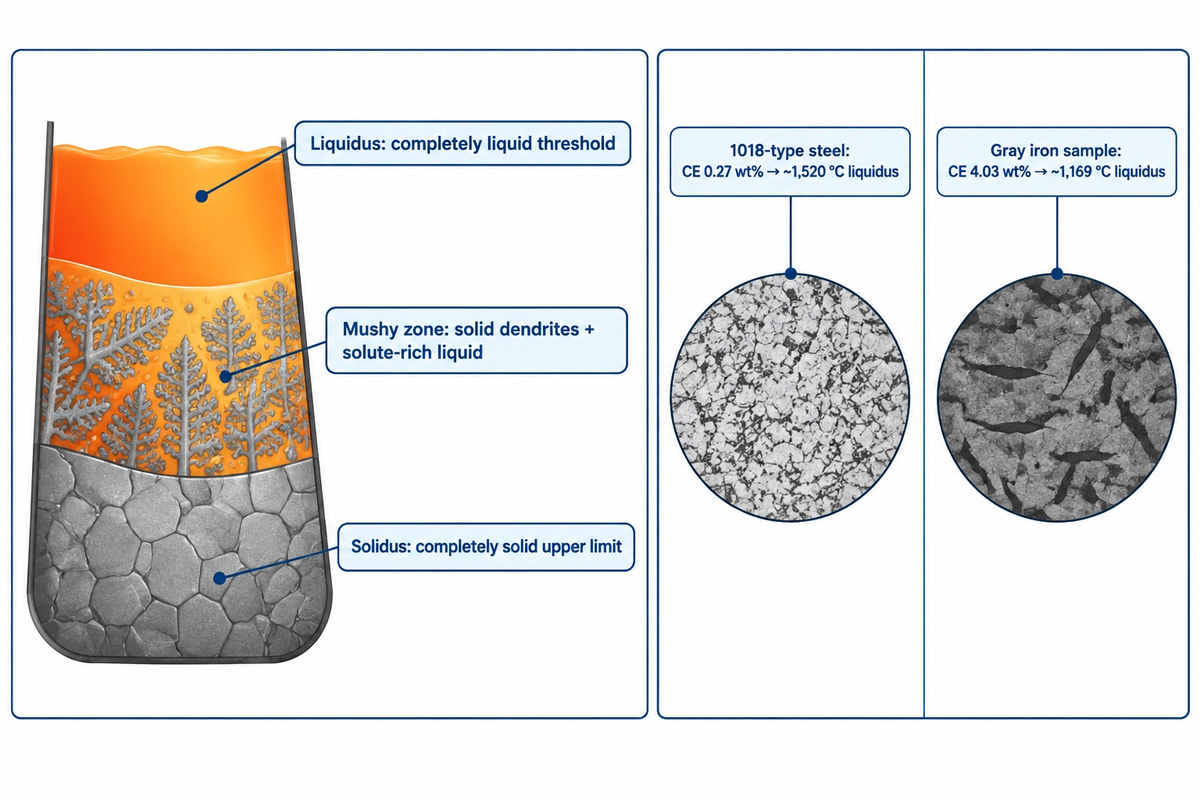
Water or an organic substance made of a discrete molecule melts at a sharp threshold. Commercial steels and cast irons behave differently as interstitial and substitutional atomic lattices. Under the NIST definitions of phase equilibrium, the solidus defines the highest temperature at which an alloy is completely solid, while the liquidus defines the lowest temperature at which it’s completely liquid. Between the two there exists a two-phase zone, which is slushy and in which solid dendrites are present in a solute-rich liquid.
On the binary Fe-C diagram at 1 atm, the liquidus begins at pure iron’s ~1,538 °C melting point. Low-carbon compositions cross a peritectic reaction near 1,493 °C (2,719 °F) involving liquid, delta-ferrite, and austenite. Liquidus temperatures then fall steadily with rising carbon toward the 4.3 wt% C eutectic composition shown in the Cambridge DoITPoMS ferrous phase guide, melting near 1,147 °C. Because carbon depresses iron’s liquidus, online charts claiming carbon steel melts at 1,593 °C (2,900 °F) contradict binary phase physics.
The 3-Point Solidus-to-Liquidus Reference
The 3-Point Solidus-to-Liquidus Reference separates incipient grain-boundary melting, mushy zone hot tearing, and liquidus pouring superheat risks across ferrous alloys.
- Point 1 (Solidus Ceiling): Normalizing and solid-state forging keep the workpiece below its incipient melting temperature. Vacuum brazing melts the filler metal while keeping the parent metal solid.
- Point 2 (Mushy-Zone Band): High-carbon 1095 steel spans a 120 °C mushy zone (1,355-1,475 °C), raising hot-tearing risk compared with near-eutectic cast irons.
- Point 3 (Liquidus Plus Superheat): Foundries superheat molten metal above liquidus to delay premature freezing during mold filling, adjusting superheat for alloy chemistry, wall thickness, and mold heat loss.
In Fe-C-Si foundry melts, silicon shifts the eutectic toward lower carbon levels as explained in Cambridge DoITPoMS cast-iron metallurgy, while phosphorus further lowers eutectic carbon. Metallurgists track this shift with Carbon Equivalent: CE = %C + (%Si + %P) / 3. For hypoeutectic gray irons, foundries estimate liquidus with the thermal-arrest formula TL (°C) ≈ 1,669 − 124 × CE.
Cooling rate impacts microsegregation and solidification in sand and permanent mold castings. Equilibrium solidus and liquidus boundaries are determined by the composition of the alloy and the pressure. Slow cooling of heavy casting bosses allows carbon to diffuse and graphite to precipitate. Rapid cooling against thin mold walls stops graphite from nucleating, resulting in the formation of iron carbide.
Worked Example: Carbon Equivalent and Liquidus (Assumed inputs: Gray Cast Iron melt with 3.30 wt% C, 2.10 wt% Si, 0.09 wt% P vs. Low-Carbon Steel melt with 0.18 wt% C, 0.25 wt% Si, 0.03 wt% P at 1 atm):
| Calculation Step / Parameter | Gray Cast Iron Sample (Hypoeutectic) | Low-Carbon Steel Sample (1018 Type) |
|---|---|---|
| Assumed Chemistry (wt%) | 3.30 wt% C / 2.10 wt% Si / 0.09 wt% P | 0.18 wt% C / 0.25 wt% Si / 0.03 wt% P |
| Silicon + Phosphorus Term: (%Si + %P) / 3 | (2.10 + 0.09) / 3 = 0.73 wt% | (0.25 + 0.03) / 3 = 0.093 wt% |
| Calculated Carbon Equivalent (CE) | 3.30 + 0.73 = 4.03 wt% (near 4.3 wt% eutectic) | 0.18 + 0.093 = 0.27 wt% (far below eutectic) |
| Resulting Liquidus Temperature | ~1,169 °C (2,136 °F) via 1,669 − 124 × 4.03 | ~1,520 °C (2,768 °F) on low-C Fe-C liquidus |
Boundary note: The linear 1,669 − 124 × CE equation applies only to unalloyed hypoeutectic Fe-C-Si-P cast irons (CE 3.5-4.3 wt%). Low-carbon and high-alloy steels follow different peritectic and multi-element slopes.
Carbon, Alloy and Stainless Steel Melting Ranges by Grade
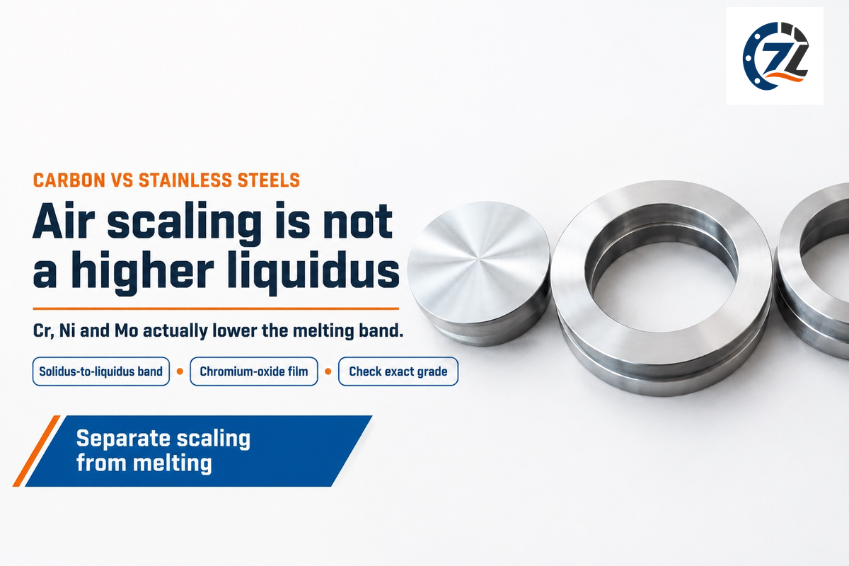
The commercial wrought steels tabulated below melt between 1,355 °C and 1,530 °C (2,471-2,786 °F) at 1 atm. British Stainless Steel Association (BSSA) tables place Type 304 stainless at 1,400-1,450 °C and Type 316 at 1,375-1,400 °C. Those ranges sit 75-125 °C below 1018 mild steel’s liquidus because Cr-Ni-Mo alloying additions documented in BSSA stainless melting guidance depress the iron liquidus.
That misleads a lot of fabricators. Many believe stainless steels possess a higher melting point because they think stainless steel can handle hot exhaust gas better than mild steel.
Heavy additions of chromium (16-25 wt%), nickel (8-20 wt%), and molybdenum (2-3 wt%) actually depress both solidus and liquidus. Type 316L stainless exhibits a tight 25 °C freezing range (1,375-1,400 °C), whereas high-carbon 1095 steel spans a 120 °C freezing band (1,355-1,475 °C). Stainless grades survive hot air because thin chromium-oxide surface films slow oxygen diffusion, not because the base metal melts higher.
In dissimilar welds between Type 304 stainless steel and AISI 1018 steel, the 75 °C liquidus mismatch tends to make the weld pools more difficult to control. In WIPO patent WO2025240686A1, heating wide-melting-range braze alloys too slowly lets low-melting liquid drain away and leave a porous skull. Medium-carbon Cr-Mo grades, like 4140, require preheat and interpass temperatures outlined in The Fabricator’s heat-treatable steel welding guide.
Melting intervals vary across stainless steel sub-families due to ferrite and austenite stabilizers pulling the phase diagram in opposite directions. Nickel-free Type 410 (martensitic) and Type 430 (ferritic) steels have a higher liquidus at 1,510-1,530 °C, which is close to that of plain mild steel. Once 10-14 wt% nickel and 2-3 wt% molybdenum enter Type 316, the alloy’s liquidus drops to 1,400 °C. Welders switching from mild steel plate to thin 316 sheet lower amperage to prevent burn-through.
| Grade / Specification | Nominal C (wt%) | Key Alloying (wt%) | Solidus-Liquidus (°C) | Solidus-Liquidus (°F) |
|---|---|---|---|---|
| Pure Elemental Iron (Fe) | <0.01 wt% | None | ~1,538 °C | ~2,800 °F |
| AISI 1018 Mild Steel | 0.15-0.20 wt% | 0.60-0.90 wt% Mn | 1,480-1,525 °C | 2,696-2,777 °F |
| AISI 1045 Medium-Carbon Steel | 0.43-0.50 wt% | 0.60-0.90 wt% Mn | 1,440-1,505 °C | 2,624-2,741 °F |
| AISI 1095 High-Carbon Steel | 0.90-1.03 wt% | 0.30-0.50 wt% Mn | 1,355-1,475 °C | 2,471-2,687 °F |
| AISI 4140 Cr-Mo Alloy Steel | 0.38-0.43 wt% | 0.80-1.10 wt% Cr / 0.15-0.25 wt% Mo | 1,415-1,495 °C | 2,579-2,723 °F |
| Type 410 Martensitic Stainless | ≤0.15 wt% | 11.5-13.5 wt% Cr | 1,480-1,530 °C | 2,696-2,786 °F |
| Type 430 Ferritic Stainless | ≤0.12 wt% | 16.0-18.0 wt% Cr | 1,425-1,510 °C | 2,597-2,750 °F |
| Type 304 Austenitic Stainless | ≤0.08 wt% | 18.0-20.0 wt% Cr / 8.0-10.5 wt% Ni | 1,400-1,450 °C | 2,552-2,642 °F |
| Type 316 / 316L Austenitic Stainless | ≤0.08 wt% (0.03 wt% L) | 16.0-18.0 wt% Cr / 10.0-14.0 wt% Ni / 2.0-3.0 wt% Mo | 1,375-1,400 °C | 2,507-2,552 °F |
Composition window note: Interval sections of tabulated grades roughly correspond to nominal chemistries. Single-heat solidus and liquidus values shift slightly with ladle chemistry and interdendritic segregation described by NIST solidification theory.
Cast Iron, Pig Iron and Wrought Iron Melting Temperatures Compared
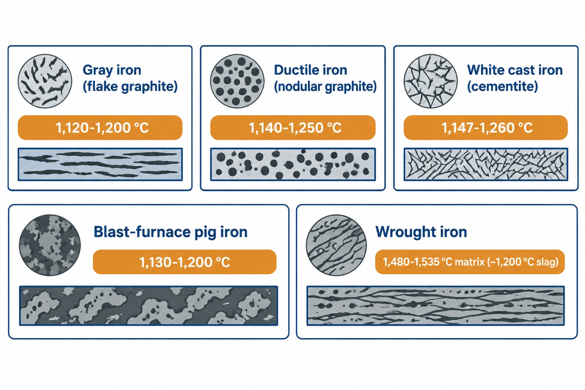
Commercial gray and ductile cast irons melt across roughly 1,120-1,250 °C (2,048-2,282 °F). Penticton Foundry lists approximately 1,121-1,160 °C (2,050-2,120 °F) for its Class 30 gray iron, whereas ASTM A48/A48M-22 classifies gray iron by tensile strength. Wrought iron (<0.08 wt% C) melts much higher at 1,480-1,535 °C in its ferrite matrix.
Various iron family alloys have a strong affinity to form carbon-rich structures, as documented in Cambridge DoITPoMS micrographs. Blast-furnace pig iron contains 3.8 to 4.7 wt% carbon with silicon and phosphorus and melts around 1,130 to 1,200 °C as raw melt stock. Gray iron precipitates graphite flakes that inhibit vibration in machine beds. Magnesium treatment of ductile iron promotes graphite nodules and improves ductility relative to gray iron when considering brittleness in cast iron microstructures. Low-silicon white cast iron traps carbon as hard cementite for wear liners.
Several online charts and social-media snippets claim wrought iron melts up to 1,593 °C (2,900 °F). That figure is a copy-paste error that exceeds pure iron’s ~1,538 °C equilibrium ceiling at 1 atm. Even ultra-clean wrought iron approaches 1,538 °C only at its upper limit. Meanwhile, wrought iron’s 1-2 wt% entrained silicate (fayalite) slag stringers soften and liquefy near 1,200 °C (2,192 °F), more than 280 °C below its ferrite matrix.
| Iron Family Type | Typical C / Si (wt%) | Microstructure / Second Phase | Melting Range (°C) | Melting Range (°F) |
|---|---|---|---|---|
| Gray Cast Iron (ASTM A48) | 2.9-3.6 wt% C / 1.8-2.8 wt% Si | Flake graphite in pearlite/ferrite | 1,120-1,200 °C | 2,048-2,192 °F |
| Ductile Cast Iron (Nodular) | 3.2-3.8 wt% C / 2.2-2.8 wt% Si | Nodular graphite (Mg-treated) | 1,140-1,250 °C | 2,084-2,282 °F |
| White Cast Iron (Abrasion Grades) | 2.5-3.6 wt% C / 0.5-1.3 wt% Si | Iron carbide (cementite) + pearlite | 1,147-1,260 °C | 2,097-2,300 °F |
| Blast-Furnace Pig Iron | 3.8-4.7 wt% C / 0.5-2.5 wt% Si | Brittle high-carbon remelt charge | 1,130-1,200 °C | 2,066-2,192 °F |
| True Wrought Iron | <0.08 wt% C / 1-2 wt% slag | Ferrite matrix + ~1,200 °C silicate slag | 1,480-1,535 °C | 2,696-2,795 °F |
Why does wrought iron melt near pure iron while cast iron melts much lower?
Wrought iron holds less than 0.08 wt% dissolved carbon, keeping its ferrite matrix close to pure iron at 1,480-1,535 °C. Cast iron carries 2.9-3.8 wt% carbon and 1.8-2.8 wt% silicon, shifting its Carbon Equivalent toward the 4.3 wt% C eutectic in Cambridge DoITPoMS diagrams and melting near 1,147 °C. That lowers gray and ductile iron melting intervals to roughly 1,120-1,250 °C.
Supplementary Comparison: Iron vs Common Engineering Metals
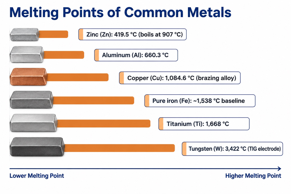
Compared with cast iron and wrought iron alloys, pure iron (~1,538 °C) melts well above zinc (419.5 °C), aluminum (660.3 °C), yellow brass (905-932 °C), and copper (1,084.6 °C) at 1 atm. Titanium (1,668 °C) and tungsten (3,422 °C) melt higher in standard elemental melting tables.
Teams looking to check metal melting points across multi-material assemblies can pair those thresholds with Dartmouth’s creep and deformation-mechanism references. Yet creep, softening, oxidation, and joint or coating degradation cap safe service temperatures before the lowest-melting part liquefies. Galvanized zinc coatings melt at 419.5 °C and boil at 907 °C. Welding over unground galvanized steel traps high-pressure zinc vapor in the freezing steel pool and releases oxide fumes.
Similar rules apply to braze and wear surface pairings across shop assemblies. Yellow brass and pure copper liquefy at 905-1,084.6 °C, permitting furnace operators to braze steel joints without melting the parent steel. Yet if copper-brazed or copper-contaminated steel is hot-worked above 1,085 °C under tensile stress, liquid copper penetrates austenite grain boundaries and triggers surface hot-shortness cracking.
| Engineering Metal | Melting Point (°C) | Melting Point (°F) | Shop-Floor Thermal Interaction with Iron / Steel |
|---|---|---|---|
| Zinc (Zn) | 419.5 °C | 787 °F | Boils at 907 °C on galvanized steel; grind off before arc welding |
| Aluminum (Pure Al) | 660.3 °C | 1,221 °F | Forms brittle Fe-Al intermetallics if fusion welded directly to steel |
| Yellow Brass (Cu-Zn) | 905-932 °C | 1,661-1,710 °F | Used for braze-welding cast iron without melting the base casting |
| Copper (Pure Cu) | 1,084.6 °C | 1,984 °F | Vacuum brazing filler for steel; liquid Cu causes hot shortness >1,085 °C |
| Nickel (Pure Ni) | 1,455 °C | 2,651 °F | Primary filler metal (Ni / Fe-Ni) for cold repair welding of cast iron |
| Iron (Pure Fe Reference) | ~1,538 °C | ~2,800 °F | Baseline high melting structural metal; alloyed to tune range |
| Titanium (Pure Ti) | 1,668 °C | 3,034 °F | Reacts rapidly with oxygen and nitrogen above 500 °C |
| Molybdenum (Pure Mo) | 2,623 °C | 4,753 °F | Used for vacuum heat-treatment furnace hot-zone hardware |
| Tungsten (Pure W) | 3,422 °C | 6,192 °F | Non-consumable GTAW (TIG) electrode for welding steel and stainless |
Which metal has the highest melting point?
Tungsten (W) has the highest melting point of any pure metal at 3,422 °C (6,192 °F / 3,695 K) at 1 atm in standard elemental melting tables. This threshold is 1,884 °C above pure iron, allowing non-consumable tungsten TIG electrodes to weld steel cleanly without melting.
Pre-Melting Softening, Oxide Scale and High-Temperature Service Limits
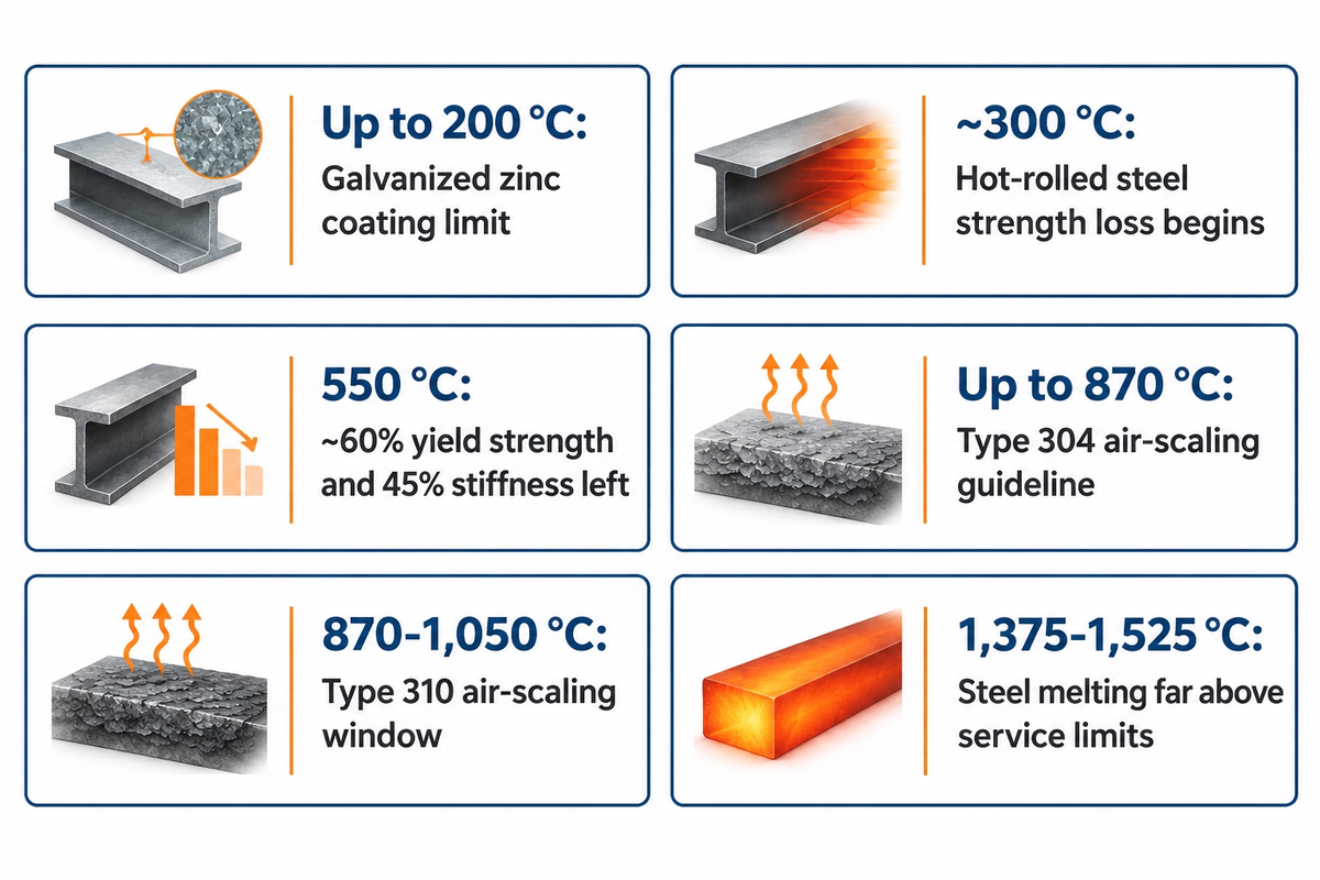
Carbon and stainless steels don’t melt at 1,000 °F (538 °C) or 1,000 °C (1,832 °F). However, Steel Construction Institute guidance shows hot-rolled steel loses strength near 300 °C. By 550 °C, it retains approximately 60% yield strength and 45% stiffness.
“Strength loss for steel is generally accepted to begin at about 300°C and increases rapidly after 400°C. By 550°C steel retains approximately 60% of its room temperature yield strength, and 45% of its stiffness.”
Sizing an exhaust flange or furnace jig from melting charts causes distortion long before solidus. Engineers evaluate the elevated-temperature yield drop on a stress-strain curve and creep limits. Elevated temperatures also reduce cold-work strengthening in cold-formed sections and cause further tempering softening in quenched-and-tempered alloy steels. Quality assurance evaluates post-exposure softening with Brinell and Rockwell metal hardness tests.
Air oxidation sets a separate ceiling. During air heating, plain carbon steel develops hematite and magnetite (~1,597 °C melting point) scale layers. Wustite (~1,377 °C melting point) forms an inner scale layer above roughly 570 °C. Heavy mill scale can impede smooth arc fusion and trap inclusions, as noted in The Fabricator’s GMAW welding guidance. BSSA tables place 304 and 310 stainless in the same 1,400-1,450 °C melting band. Yet continuous air-scaling guidelines sit at 870 °C for 304 versus 1,050 °C for 310.
Cyclic heating makes oxide spalling worse than steady furnace holds. Because oxide layers and base steel expand at different rates, repeated startups crack loose scale and expose fresh iron underneath. Service limits also depend on furnace atmosphere: sulfur-bearing flue gases, carburizing gases, and steam lower safe operating ceilings below clean dry-air guidelines. When structural brackets or exhaust housings reach 600 °C under sustained load, plain carbon steel can suffer steep yield loss, creep deformation, and oxidation while remaining solid.
The 4-Check Ferrous Thermal Window
The 4-Check Ferrous Thermal Window screens strength retention, oxide scaling, phase stability, and surface coating limits before approving high temperature ferrous grades.
| Continuous Metal Temp (Air) | Suitable Alloy Family | Primary Limiting Mechanism | Disqualifier / Engineering Boundary |
|---|---|---|---|
| Up to 200 °C (392 °F) | Galvanized or Zinc-Plated Mild Steel | Coating peeling & passivation loss | Not Recommended above 200 °C due to zinc flaking |
| Moderate cyclic heat | Gray Cast Iron (ASTM A48) | Thermal fatigue, graphitization & internal oxidation | Cyclic thermal shock can crack flake iron; prolonged heat causes growth |
| Up to 400 °C (752 °F) | Carbon Steel (1018 / 1045) | Onset of rapid yield-strength drop | Hot-rolled yield falls fast above 400 °C; air scale thickens >450 °C |
| 400-520 °C (752-968 °F) | 4140 / Cr-Mo Alloy Steel (Tempered) | Further tempering & creep onset | Keep service well below final temper temperature to hold hardness |
| 500-600 °C (932-1,112 °F) | Cr-Mo Pressure-Vessel Steels | Creep deformation & air oxidation | Plain carbon steel retains ~60% yield at 550 °C and creeps under load |
| 600-650 °C (1,112-1,202 °F) | Type 410 Martensitic Stainless | Temper softening & scaling limit | 12 wt% Cr slows steam scale but softens under sustained stress |
| 650-800 °C (1,202-1,472 °F) | Type 316L / 321 Austenitic Stainless | Carbide sensitization & sigma phase | Low-C or Ti stabilization reduces sensitization; long holds risk sigma phase |
| Up to 870 °C (1,598 °F) | Type 304 Austenitic Stainless | BSSA air-scaling guideline | Cr-rich oxide slows scaling; creep restricts load-bearing stress lower |
| 870-1,050 °C (1,598-1,922 °F) | Type 310 / 310S Stainless (25Cr-20Ni) | High-temperature creep & spalling | Melts at 1,400-1,450 °C; verify creep allowable stress near 1,000 °C |
| 1,050-1,150 °C (1,922-2,102 °F) | Creep-rated Ni alloys; Mo in vacuum/inert gas | Creep, incipient melting & air oxidation | Standard steels lose load capacity; Mo oxidizes rapidly in open air |
Thermal Thresholds in Casting, Welding, Forging and CNC Machining
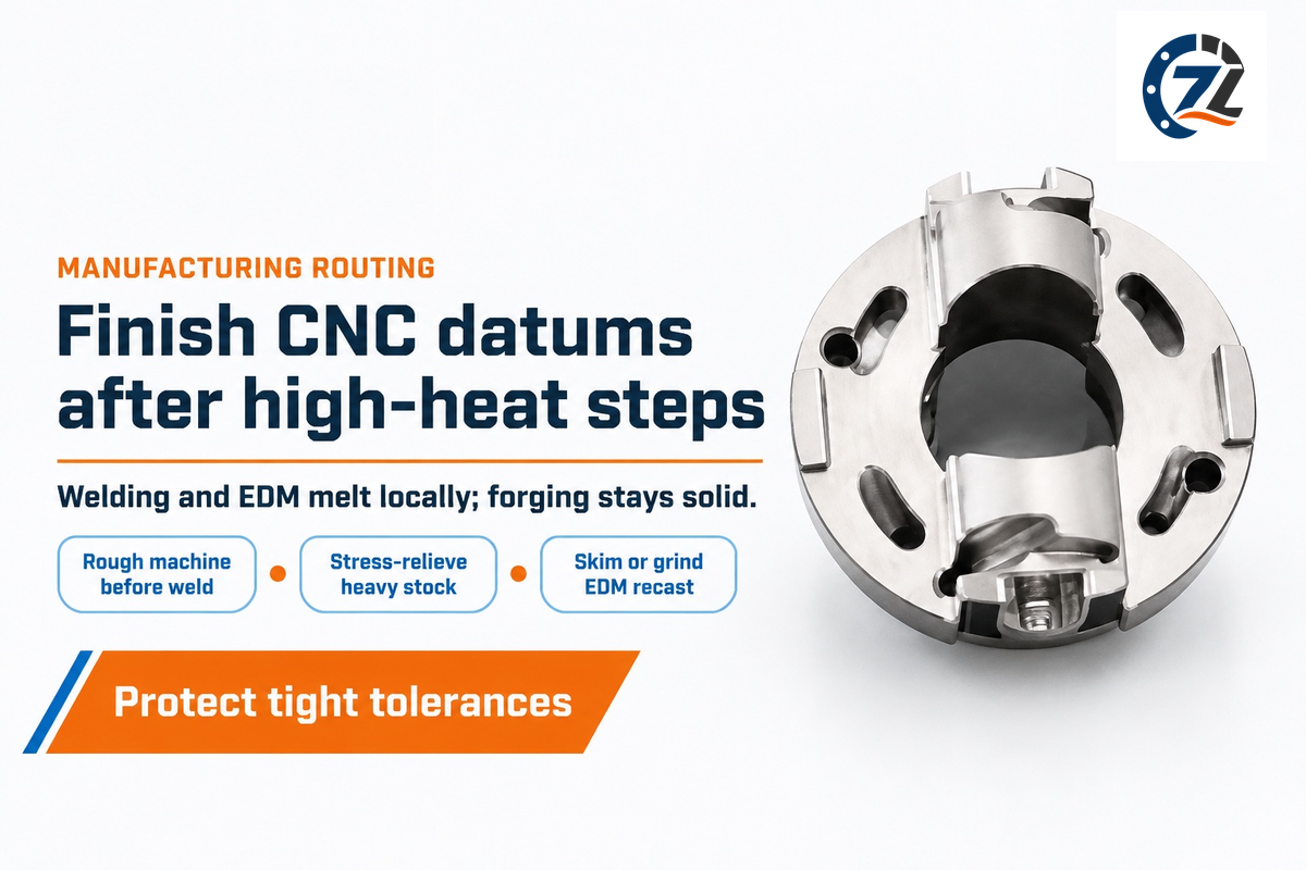
Foundry pouring superheats molten metal above liquidus and fusion welding or EDM locally melts metal. On the other hand, steel hot forging (800-1,250 °C or 0.6-0.85 homologous melting temperature in Dartmouth Engineering Table 19.8) and CNC cutting stay below solidus. Making tight-tolerance parts requires finishing CNC datums after high-heat steps.
Conventional closed-die forging shapes solid steel billets at 800-1,250 °C, unlike semi-solid thixoforging between solidus and liquidus in U.S. Patent US7472674B2. Depending on alloy composition and temperature within 800-1,250 °C, carbon and low-alloy steels are hot-forged in austenite or two-phase ferrite-austenite, while ferritic stainless steels remain ferritic. Rapid die deformation adds an adiabatic rise up to 0.3 of absolute melting temperature, so overheating billets near solidus risks grain-boundary burning.
In CNC milling and turning, high-speed shear deformation generates an adiabatic rise up to 0.4 of absolute melting temperature in Dartmouth’s machining analysis. Most cutting heat exits with the chip, and graphite flakes lubricate gray-iron cuts compared with gummy low-carbon steel. Fusion welding crosses liquidus within the weld pool, while the heat-affected zone spans near-liquidus to ambient, as detailed in The Fabricator’s metallurgy review. Hot-welding repairs of cast iron can use 550-650 °C furnace preheating and slow cooling to reduce hard chill zones, whereas cold repairs use nickel fillers and low heat input.
Engineering Note on EDM Recast Layers: Wire and sinker EDM sparks vaporize and melt microscopic craters that re-freeze into a hard recast skin. Peer-reviewed wire-EDM tests published in NIH PubMed Central (PMC9918936) measured a 6.2 ± 2.1 μm recast layer with microcracks on Inconel 718 alongside 4-10 μm values on Ti6Al4V. Hardened tool steels form comparable white layers, requiring skim cuts or grinding via recast layer control in electrical discharge machining.
| Manufacturing Process | Typical Peak Temperature | Relation to Solidus / Liquidus | CNC Machining Sequencing Rule |
|---|---|---|---|
| Sand / Investment Casting | 1,200-1,620 °C (alloy-dependent) | Superheated above liquidus for mold fill | Allow 1.5-3.0 mm machining stock; stress-relieve before finish boring |
| Hot Forging & Rolling | 800-1,250 °C (+ up to 0.3 Tm adiabatic) | Solid-state plastic flow below solidus | Normalize or anneal forgings before precision CNC roughing |
| Arc / Laser Fusion Welding | >1,450-1,600 °C in weld pool | Crosses liquidus locally; steep HAZ gradient | Rough machine → weld → stress-relieve → finish CNC datums |
| CNC Milling & Turning | Up to 0.4 Tm shear-zone rise | Strictly solid-state (heat leaves in chips) | Use coated carbide tools + flood coolant to hold tight tolerances |
| Wire / Sinker EDM | Localized plasma crater melting | Crosses liquidus & boiling in μm skin | Specify skim passes, grinding, or honing to strip recast white layer |
Specifying Chemistry, Mill Test Reports and CNC Supplier Controls
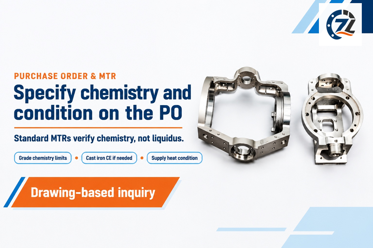
Managing the thermal limits of welding, casting, and CNC machining starts on the purchase order. EN 10204:2004 Type 3.1 certificates state the specific tests required by the product standard and purchase order. Typical orders verify that the raw material conforms to grade by limiting the composition of elements that impact mechanical properties (e.g. 0.15-0.20 wt% C in 1018 or 16.0-18.0 wt% Cr and 2.0-3.0 wt% Mo in 316). Values for the solidus and liquidus appear on certificates only if the buyer specifies additional thermal analysis and definite melting targets in the order.
Two specification traps frequently catch procurement teams off guard.
Under ASTM A48/A48M-22, gray iron castings are classified by minimum tensile strength (such as Class 30 or Class 40). Chemical composition stays subordinate unless the purchase order specifically states carbon, silicon, or Carbon Equivalent limits. If vacuum brazing or casting requires measured solidus and liquidus acceptance limits, state those target temperature limits in the purchase order. Buyers can pair that callout with differential scanning calorimetry per ASTM E794-06(2018) as a supplementary laboratory requirement.
There are options for incoming analyzers. Handheld X-ray fluorescence (XRF) guns separate 304 from 316 stainless in seconds via molybdenum, yet XRF detectors can’t measure light-element carbon to tell 1018 apart from 1045 steel. To validate carbon wt%, spark OES or combustion testing is required along with our material RFQ completeness checklist.
On machined weldments and heavy castings, residual stress relief matters more to part geometry than handbook liquidus tables. Rough milling removes outer mill skin and unlocks asymmetric rolling or casting stresses. Stress-relief annealing after finish boring can distort tight bearing bores, so finishing both reference datums and the bores themselves after stress relief preserves concentricity.
Ferrous Part RFQ & MTR Verification Checklist
| RFQ Specification Item | What to Call Out on Drawing / PO | Verification Method |
|---|---|---|
| Base Standard & Grade | Specific ASTM / AISI / ISO designation + condition (e.g., 4140 Q&T) | EN 10204 Type 3.1 heat-traceable certificate |
| Carbon & Alloy Chemistry | State C, Si, P, S, or Cu order limits on ASTM A48 or welded EAF steel | Spark OES or combustion test for carbon wt% |
| Thermal / Stress-Relief Step | State rough-machine → stress-relieve / Q&T → finish-machine sequence | Furnace chart + Rockwell / Brinell hardness log |
| EDM & Weld Surface Control | Specify recast-layer removal and surface-defect acceptance criteria | Metallographic recast check + crack & CMM inspection |
What material verification and tolerance controls should a custom CNC machining supplier provide for steel and cast iron components?
A qualified CNC machining shop would offer heat-traceable EN 10204:2004 Type 3.1 certificates to show adherence to the required chemistry and perform incoming spark OES, if that was specified. The shop should document the stress-relief sequencing as well as EDM recast cleanup and final CMM dimensional reports.
2025–2026 Ferrous Metallurgy Advances: Scrap Tramp Elements and Hydrogen Melting
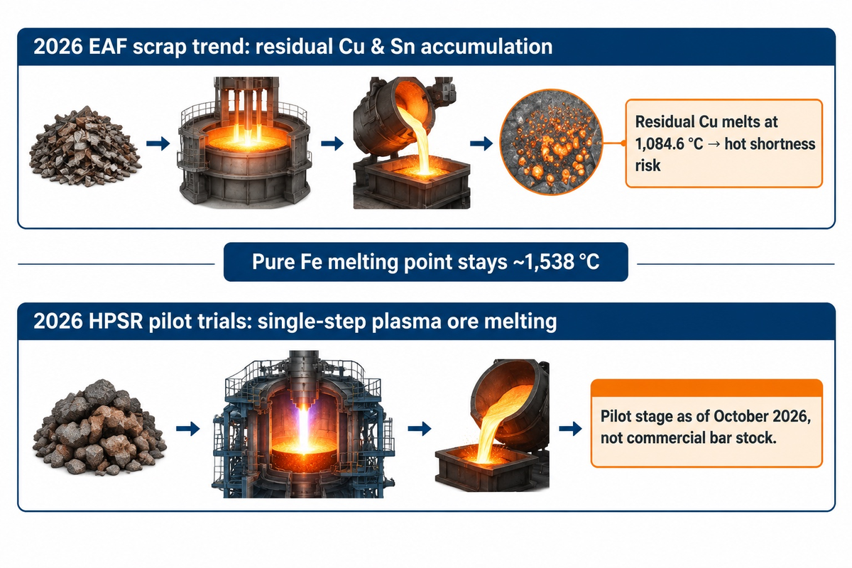
Electric-arc scrap recycling and 2025-2026 hydrogen reduction research won’t affect pure iron’s ~1,538 °C. However, increasing post-consumer scrap shares tracked in 2026 ACS steelmaking research can accumulate residual copper and tin in EAF steelmaking. Users of recycled carbon steel bar should evaluate their tramp-element limitations.
Scrap-fed electric arc furnace steelmaking continues to expand globally with demand trends in the Worldsteel October 2026 Short Range Outlook. Copper and tin are nobler than iron, so oxygen blowing can’t strip them from liquid steel. In 2026 arXiv steel-scrap supply chain studies, copper contamination in recycled scrap induces hot shortness. During reheating, residual copper enriches beneath oxide scale, melts at 1,084.6 °C, and wets austenite grain boundaries.
Primary ore reduction is also advancing through hydrogen plasma smelting reduction (HPSR). HPSR reactors reduce and melt ore in a single step with hydrogen plasma arcs which have been tested in the 2026 MatTech pilot trials and DOE PPPL plasma arc studies. As of October 2026, HPSR is at the pilot stage rather than at commercial bar production. Verify copper wt% on mill certificates against the governing ASTM or ISO grade specification and any purchase-order residual cap. Grades such as 17-4 PH intentionally contain ~4 wt% copper, whereas hot-worked carbon steels cap residual copper per specification.
Frequently Asked Questions
At what temperature does pure iron boil compared with its melting point?
Pure elemental iron boils at 2,861 °C (5,182 °F / 3,134 K) at 1 atm, sitting 1,323 °C above its ~1,538 °C melting point. Even so, significant iron and alloying-element vapor pressure develops well below 2,861 °C inside fiber-laser keyhole welds, electron-beam weld chambers, and high-vacuum induction furnaces. Below 1 Pa in vacuum chambers, volatile manganese and copper evaporate long before iron hits 2,861 °C, requiring backfill gas control.
Why is iron’s melting point so much higher than aluminum or zinc?
Pure iron melts near 1,538 °C because its partially filled 3d electron orbitals form strong directional metallic bonds alongside its outer 4s electrons. Aluminum (660.3 °C) and zinc (419.5 °C) have lower melting points because aluminum relies on outer sp-electron shells while zinc has filled d-electron shells with weaker cohesion. Galvanized zinc coatings therefore vaporize at 907 °C during arc welding on steel.
Can you lower the melting point of iron for casting?
Carbon and silicon lower cast-iron melting temperatures: Penticton Foundry lists approximately 1,121–1,160 °C for Class 30 gray iron, while the broader gray- and ductile-iron ranges summarized here extend to approximately 1,250 °C. That lowers gray and ductile cast iron melting intervals to roughly 1,120-1,250 °C, about 290-420 °C below pure iron. That drop improves thin-wall mold filling and lowers furnace energy demand, though cast irons trade away wrought steel’s high tensile elongation.
Is the freezing point of iron the same as its melting point?
At equilibrium and 1 atm, pure iron melts and freezes at the same temperature of approximately 1,538 °C (2,800 °F). Impurities cause a liquidus-to-solidus range.
How does iron oxide (rust or mill scale) melt compared with bare iron or steel?
Magnetite mill scale melts near 1,597 °C, above 1018 steel’s 1,480-1,525 °C range. Wustite melts near 1,377 °C, and hematite decomposes to magnetite at 1,450-1,565 °C in air. Heavy mill scale can contribute to lack of fusion and oxide inclusions; grinding removes the oxide barrier, while silicon-manganese deoxidizers in ER70S-6 wire help wet light scale during GMAW.
Does high pressure change the melting point of iron?
Yes: extreme gigapascal compression in planetary-core diamond-anvil tests pushes iron’s melting point above 5,000-6,000 K, whereas normal air or vacuum furnaces shift it by less than 1 °C.
Need Precision CNC Machining for Carbon Steel, Stainless, or Cast Iron Parts?
Shanghai Zhenling Hardware Co., Ltd. machines custom carbon steel, alloy steel, stainless steel, and cast iron components from drawings with material selection support, stress-relief sequencing, and dimensional inspection. Upload your 2D drawings and 3D STEP files to request a custom CNC machining quote with drawing review.
Related Articles
- Engineering Drawing Tolerances: Datum Selection and Post-Heat-Treat Fit
- Metal Machinability Chart for Steel, Stainless, and Cast Iron
References & Sources
- NIST Center for Theoretical and Computational Materials Science: Liquidus and Solidus Phase Equilibrium Definitions.
- University of Cambridge DoITPoMS: Cast Iron Eutectic Microstructures and Ferrous Phase Guide.
- Hot-Working Windows (Table 19.8) and Adiabatic Heating from the Dartmouth College Thayer School of Engineering define hot working limits.
- NIH PubMed Central: Wire-EDM Recast Layer Characterization (PMC9918936).
- U.S. DOE Princeton Plasma Physics Laboratory (2026): “Hydrogen Plasma Smelting Reduction Arc Modelling“.
- Steel Construction Institute (SCI): “Fire Damage Assessment of Hot-Rolled Structural Steelwork“.
- ASTM Standards Catalog: “ASTM A48/A48M-22 Gray Iron Castings” and “ASTM E794-06(2018) DSC Melting Test“.
- CEN Standards Catalog: “EN 10204:2004 Metallic Inspection Documents“.
- ACS Sustainable Resource Management (2026): “Tramp-Element Constraints in EAF Steelmaking“.
- Patent Disclosures: “WO2025240686A1 Brazing Liquation” and “US7472674B2 Semi-Solid Thixoforging“.
- Reference Compilations: “Britannica Iron Allotropy“, “Wikipedia Iron Properties“, and “Elements Melting Point Data“.
- The Fabricator (FMA): “Mill Scale in GMAW“, “HAZ Gradients“, and “Welding Heat-Treatable Steels“.
- 2026 Ferrous Studies: “MatTech 2026 HPSR Pilot“, “arXiv 2026 The Steel Scrap Age“, and “Worldsteel October 2026 Outlook“.
Editorial & Technical Transparency Note: Reviewed by the Shanghai Zhenling Hardware Co., Ltd. technical team in October 2026. Constants, phase coordinates, and alloy solidus-to-liquidus intervals come from NIST, university metallurgy, BSSA, SCI, and ASTM/CEN reference standards at 101.325 kPa (1 atm). Actual melting onset and high-temperature strength depend on heat-specific chemistry, cooling rate, and load. Verify safety-critical designs against governing ASME, EN, or ASTM codes and mill certificates.