Why CMM inspection results differ is explained by changes in the complete measurement definition or part state between inspections. The reported value can move with datum alignment, temperature, fixturing, probe setup, sampled points, fitting and filtering rules, machine-specific uncertainty, or the rule used to declare conformity, even when both machines are calibrated.
Start here before blaming either CMM
- Confirm both reports describe the same measurand.
- Hold one part, program, fixture, stylus, and environment constant.
- Change one variable at a time and save the evidence.
- Compare conclusions under the same uncertainty and decision rule.
The same part can produce different values when the inspection defines or samples the measurand differently. The challenge is determining if a change in a measured value is due to a real change in a part or if it’s due to a change in the inspection used to sample, reconstruct, or evaluate the part.
No universal allowable percentage
The acceptable difference cannot be decided from two numbers alone. It depends on the characteristic, tolerance, task-specific uncertainty, correlation between results, and the governing conformity rule.
The acceptable difference cannot be decided from two numbers alone. It depends on the characteristic, tolerance, task-specific uncertainty, correlation between results, and the governing conformity rule.
Why CMM Inspection Results Differ: The Short Answer
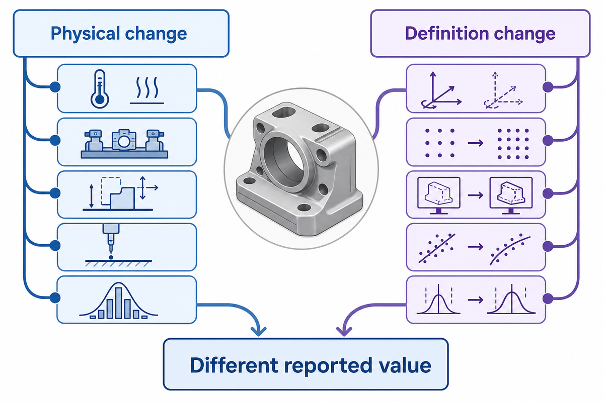
The final value can change when either inspection changes the part condition, coordinate system, contact pattern, evaluation algorithm, correction model, or decision rule, even if the same drawing label appears on both reports to a reviewer who sees the feature name and numerical result.
Physical changeTemperature, residual stress, clamping, seating, contamination, handling, or damage alters the geometry presented to the probe.
Definition changeDatums, point locations, filters, fitting rules, compensation, software settings, or rounding alter how geometry becomes a reported value.
In some cases, machine performance information alone does not prove that every inspection is aligned or supports an equivalent final result. As the NIST discussion of CMM measurement uncertainty explains, examining machine performance may show that additional measurement-specific considerations are needed before a conclusion is justified.
Result Difference Stack
Check the layers in order: part identity and state → environment → fixture → datum alignment → probe and stylus → sampling and evaluation → uncertainty and decision rule.
Check the layers in order: part identity and state → environment → fixture → datum alignment → probe and stylus → sampling and evaluation → uncertainty and decision rule.
First Confirm That Both Reports Measure the Same Thing
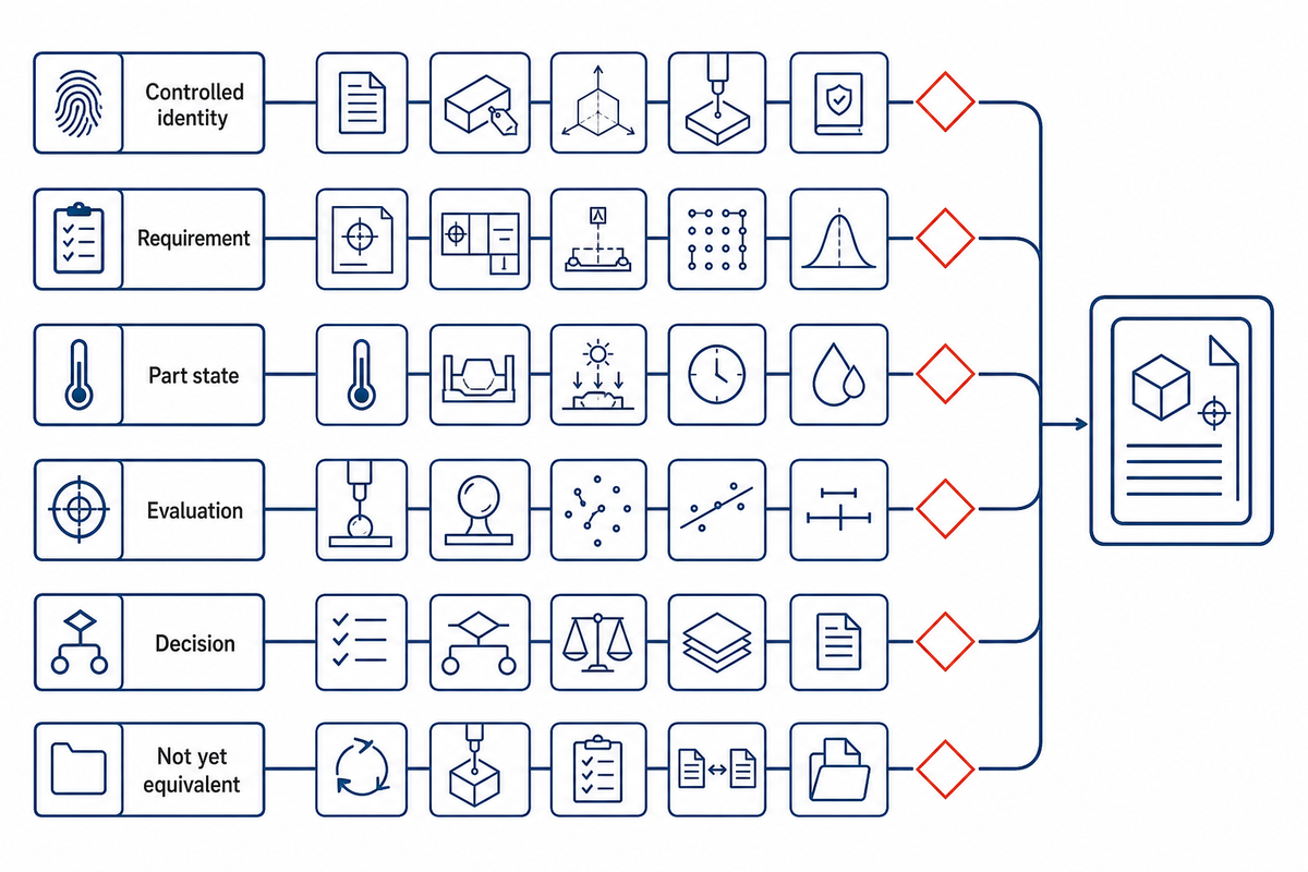
Values reported by the CMM are ready for comparison only after confirming the same part, drawing revision, characteristic definition, dimensional inspection reference frame, unit, result type, and acceptance rule. Two characteristics labeled “position” or “diameter” are not necessarily the same when the fitting method, material condition, or alignment differs.
| Field | What must match or be reconciled | Stop condition |
|---|---|---|
| Controlled identity | Part, lot, drawing/model revision, characteristic ID | Different revision or feature |
| Requirement | Nominal, tolerance, units, datum sequence, modifiers | Unlike requirement definition |
| Part state | Temperature, cleaning, coating, heat treatment, restraint | State is unknown or changed |
| Evaluation | Feature boundary, points, filter, fit, projection, compensation | Methods are not equivalent |
| Decision | Uncertainty statement, rounding, acceptance and guard-band rule | Different disposition logic |
A minimum-zone solution and a least-squares cylinder solution can both be mathematically valid yet answer different geometric questions. The same holds true for a solution in which one program operatively follows the reference frame of the drawing, and another program takes a best-fit approach in minimizing deviation.
Comparison status
If a critical field is missing, label the reports “not yet equivalent.” Do not average unlike values to create artificial agreement.
If a critical field is missing, label the reports “not yet equivalent.” Do not average unlike values to create artificial agreement.
The Result Difference Stack: Seven Layers to Check
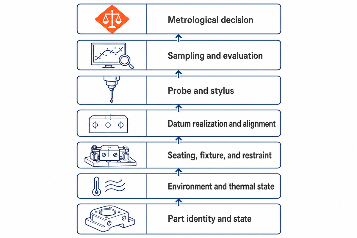
When diagnosing problems, it’s usually best to check the part and inspection definition before jumping immediately to CMM calibration. Early in the process, many variables can be altered; downstream software or a decision constraint can make a previously stable inspection appear inconsistent.
- 1. Part identity and state verify the exact part, revision, processing stage, cleanliness, and surface condition.
- 2. Environment and thermal state compare part, machine, and room trends rather than the room setpoint alone.
- 3. Seating, fixture, and restraint preserve supports, clamp sequence, contact faces, and cleaning method.
- 4. Datum realization and alignment compare datum points, constraint order, simulators, and best-fit settings.
- 5. Probe and stylus record the complete build, qualification, approach directions, and contact behavior.
- 6. Sampling and evaluation lock point distribution, scan path, filters, boundaries, and fitting rules.
- 7. Metrological decision compare verification status, task-specific uncertainty, correlation, rounding, and decision rule.
It’s usually best to alter higher constraints while holding lower constraints fixed. This generally allows a diagnostic to focus on interpreting a specific rerun instead of obtaining another pair of obscure process values.
Temperature and Part State Change the Measurand
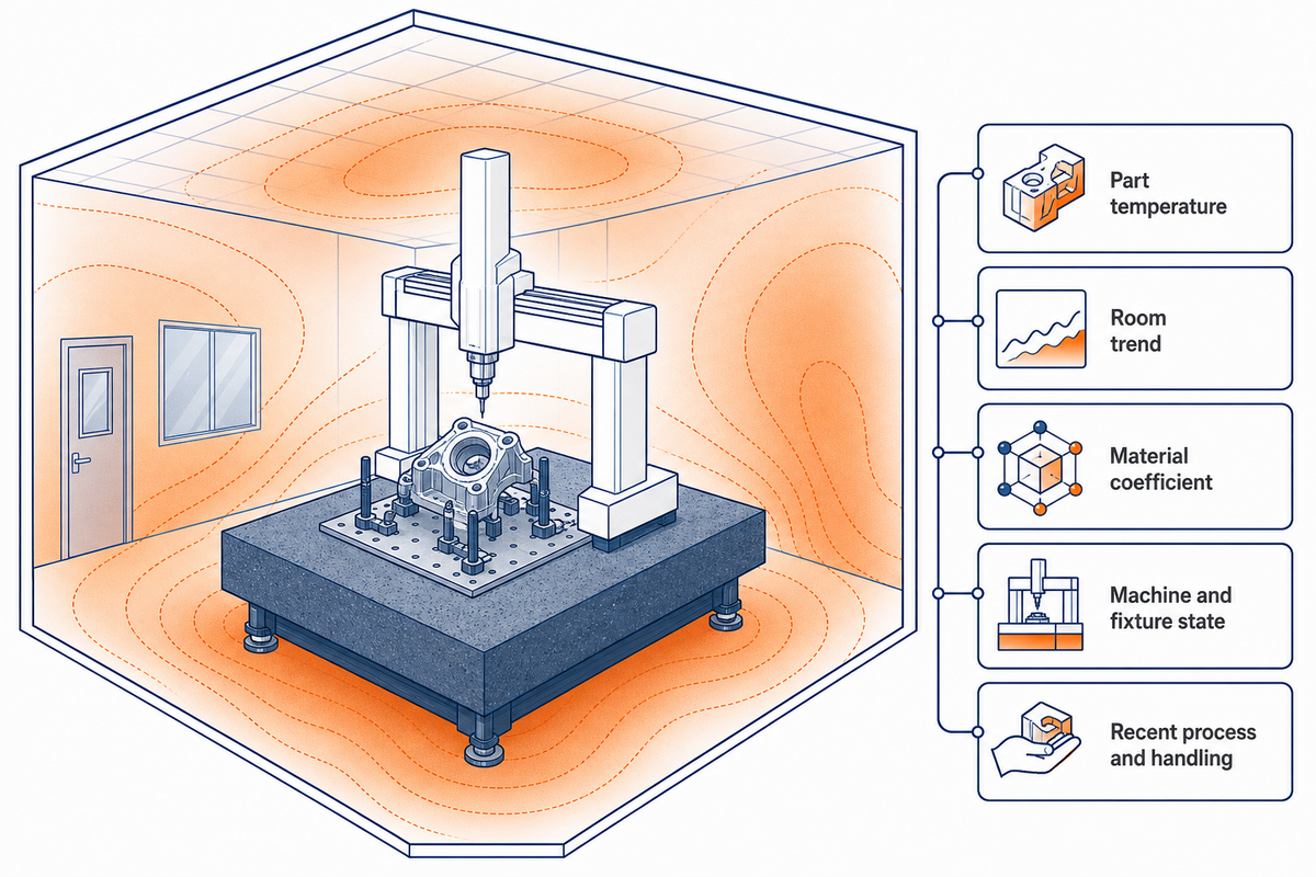
Temperature can change the physical dimensions presented for measurement. Gradients can lead to different regions of a workpiece being affected by a process to different degrees. A work area being at the reference temperature doesn’t mean that all the process components are at the same reference temperature and stable condition.
| Record | Why it matters |
|---|---|
| Part temperature and locations | One reading can miss a gradient across a large or recently machined part. |
| Room trend and stabilization interval | A setpoint does not show recent movement or whether the part equilibrated. |
| Material and coefficient used | An incorrect material coefficient changes the correction model. |
| Machine/fixture state | The measurement system and restraint can respond differently from the part. |
| Recent process and handling | Machining heat, coolant, washing, or hand contact can create local effects. |
According to ISO 1:2022, the standard reference-temperature scope for formulating geometrical and verification specifications has been defined. For a given inspection, the applicable drawing, process, and contract determine the reference-temperature scope.
Compensation is an input, not proof
A temperature-compensation entry does not prove that the part is uniform, the sensor represents the disputed feature, or the selected coefficient matches the actual material condition.
A temperature-compensation entry does not prove that the part is uniform, the sensor represents the disputed feature, or the selected coefficient matches the actual material condition.
Datum Alignment Can Move the Coordinate System
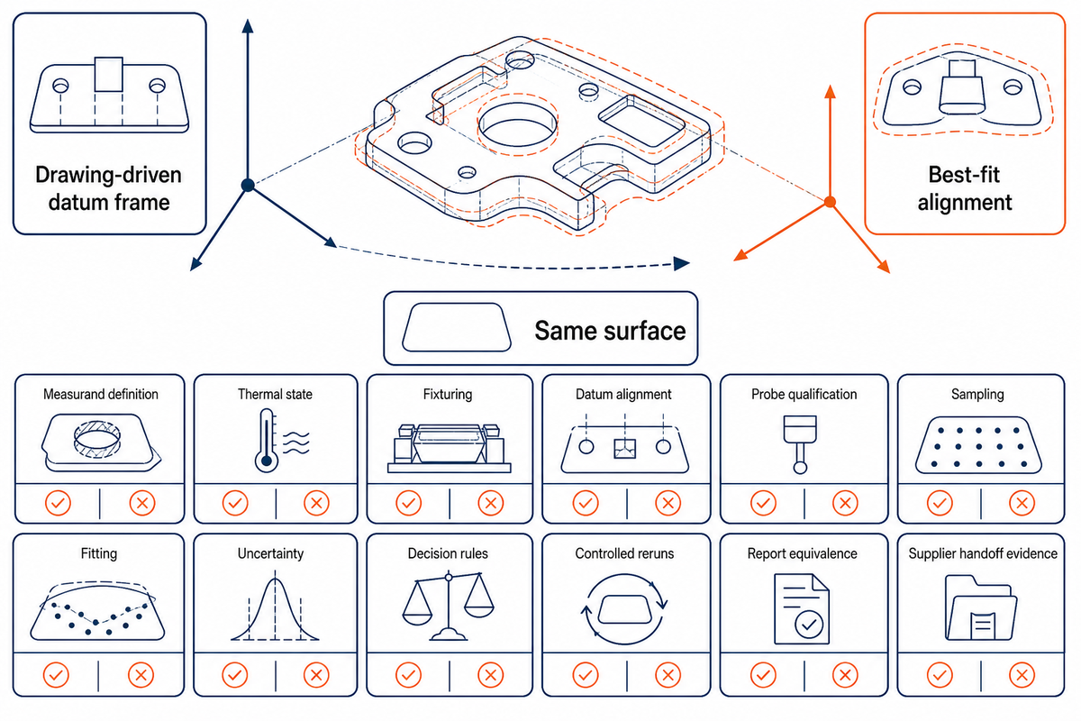
CMM datum alignment converts measured datum features into the coordinate system used to report other features. Changing datum points, constraint order, datum simulators, feature boundaries, or the use of CMM best fit alignment can rotate or translate that system, changing reported locations without changing the underlying surface.
Drawing-driven datum frame
Constrains the part according to the stated primary, secondary, and tertiary datum relationship and applicable modifiers.
Best-fit alignment
Optimizes a defined objective across selected data and may be useful for analysis, but it does not silently replace the drawing datum sequence.
When reports differ, export the alignment definition. Don’t trust the software or program name to identify the alignment definition correctly. The evidence should define the features that represent each axis and origin. It should also identify the points that were kept or removed and indicate if the fits were local or iterative.
Datum frame
Origin and axes follow controlled datum features.
Origin and axes follow controlled datum features.
≠
Best fit
Origin and axes minimize a selected set of deviations.
Origin and axes minimize a selected set of deviations.
Fixturing, Stylus Setup and Probe Qualification Change Contact
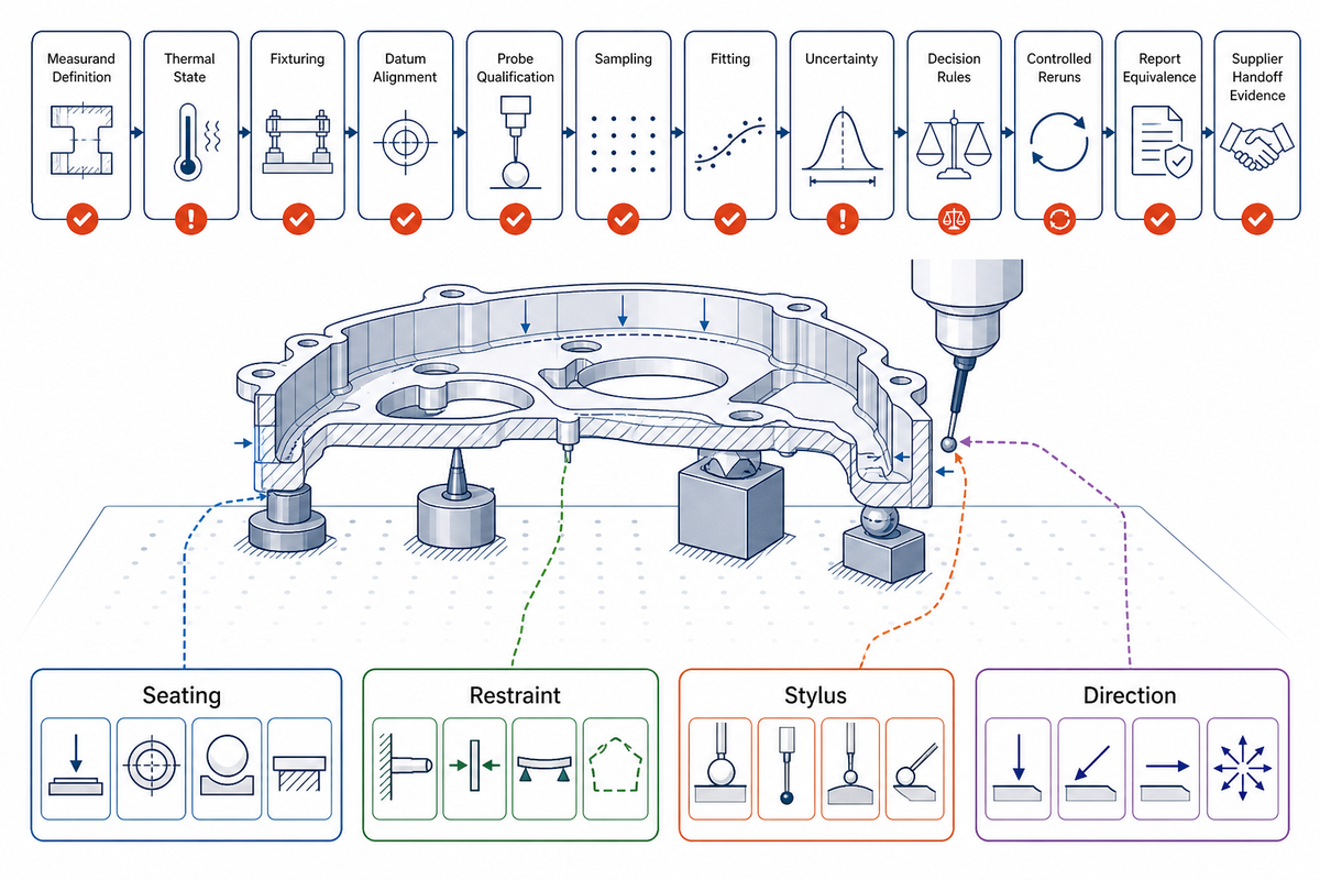
The CMM doesn’t touch the wireframe representation of a CAD model. It touches a seated, restrained physical surface, not a limited surface representation, through a specific stylus. Many factors, including the clamp load, the CMM tip, the extension, the approach direction, and the type of surface touched, affect the part being modeled and the contact being measured.
Seating
Cleanliness, burrs, contact pads, and load sequence affect how the part rests.
Cleanliness, burrs, contact pads, and load sequence affect how the part rests.
Restraint
Clamp force and support spacing can distort thin walls, flanges, tubes, or compliant features.
Clamp force and support spacing can distort thin walls, flanges, tubes, or compliant features.
Stylus
Tip, length, joints, extension, orientation, and qualification affect access and deflection.
Tip, length, joints, extension, orientation, and qualification affect access and deflection.
Direction
Touch-trigger behavior can contain approach-dependent systematic error that still repeats well.
Touch-trigger behavior can contain approach-dependent systematic error that still repeats well.
NIST has indicated that consistent repeated contact by touch trigger sensors may result in systematic probe errors. Consistently repeated contact in one direction doesn’t necessarily indicate that probe lobing or approach-direction bias has been eliminated.
Setup Evidence Card
Save a setup photograph, support and clamp locations, loading sequence, part orientation, full stylus build, qualification timestamp, probe angles, and the approach directions used for the disputed feature.
Save a setup photograph, support and clamp locations, loading sequence, part orientation, full stylus build, qualification timestamp, probe angles, and the approach directions used for the disputed feature.
Cross-method checkpoint
When a quality control team uses an optical system, hand gage, or another coordinate measuring machine to inspect the same feature, preserve the exact CMM program and method boundary. This is especially important for aerospace work, first article inspection, or micron-level disputes: “accurate and repeatable” describes a goal, while the actual measurement results still need comparable definitions and evidence.
When a quality control team uses an optical system, hand gage, or another coordinate measuring machine to inspect the same feature, preserve the exact CMM program and method boundary. This is especially important for aerospace work, first article inspection, or micron-level disputes: “accurate and repeatable” describes a goal, while the actual measurement results still need comparable definitions and evidence.
Point Strategy and Feature Fitting Change the Reported Geometry
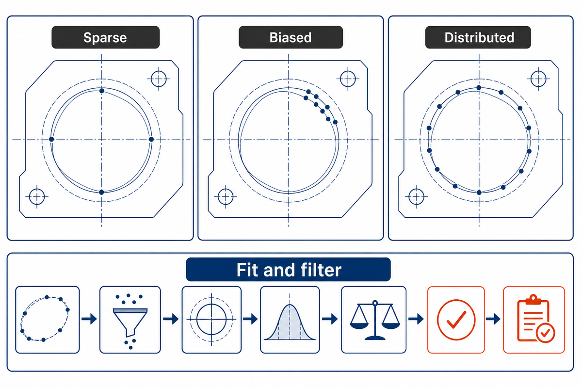
Ideally, the part surface should be represented by an even, continuous and smooth surface without imperfections. However, this isn’t always the case. Real parts may possess surface damage, irregular edges, and may be rough and/or wavy. A sparse touch pattern, a dense scan, and points concentrated on one sector sample different evidence, while fitting and filtering rules determine which ideal circle, plane, cylinder, or other feature is reconstructed.
Same Surface, Three Sampling Patterns
• • • •Sparse
May miss local form.
May miss local form.
•••••• •Biased
Overweights one sector.
Overweights one sector.
• • • • • •Distributed
Broader evidence, not automatic correctness.
Broader evidence, not automatic correctness.
Usually, the distribution of points, locations of boundaries of features, behaviors of scan, and kinds of filter depend on the measurand. The 2023 metrology report on the layouts of CMM points illustrates that, in assessing points, their location and number are to be considered jointly.
| Control | Possible effect |
|---|---|
| Least-squares vs function-specific fit | Optimizes a different mathematical objective. |
| Point exclusion and outlier rule | Changes which surface evidence enters the result. |
| Filter and cutoff | Separates surface components differently. |
| Projection and feature boundary | Can include or exclude taper, edge, or out-of-plane data. |
| Software version and rounding | Can alter implementation details or displayed disposition. |
The resources available through NIST algorithm testing exist for a reason: evaluating software with coordinate data is a metrological concern. When contractually permissible, request controlled point sets rather than only rounded result lines.
Calibration, Traceability, Uncertainty and Decision Rules Are Different Controls
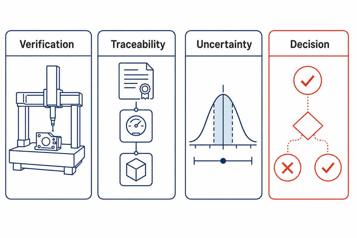
Calibration or verification and metrological traceability answer two different questions. Task-specific CMM measurement uncertainty and a conformity decision rule answer two more questions. Communicating point distribution, the feature boundary, scan behavior, and filtering allows determination of the suitability of the method for the measurand, not the boundary of the machine.
1. Verification
Did the system meet defined performance requirements?
Did the system meet defined performance requirements?
2. Traceability
Can the result relate to references through a documented calibration chain?
Can the result relate to references through a documented calibration chain?
3. Uncertainty
How much quantified doubt applies to this feature, method, and condition?
How much quantified doubt applies to this feature, method, and condition?
4. Decision
How are result and uncertainty converted into conformity?
How are result and uncertainty converted into conformity?
Two machines can’t, in general, be expected to give the same or identical results. It’s to be verified whether both results are valid and answer the same question.
Task-specific route
ISO 15530-3 describes an experimental technique using calibrated workpieces or measurement standards for task-specific CMM uncertainty. It is one bounded route, not a substitute for identifying the governing procedure and ensuring sufficient similarity.
ISO 15530-3 describes an experimental technique using calibrated workpieces or measurement standards for task-specific CMM uncertainty. It is one bounded route, not a substitute for identifying the governing procedure and ensuring sufficient similarity.
Decision rules also matter near a tolerance boundary. The current published record for ISO 14253-1 and the official ASME B89.7.3.1 scope are appropriate places to verify which conformity framework applies, rather than copying an uncited percentage from a forum.
Use the One-Part Re-run Ladder to Isolate the Cause
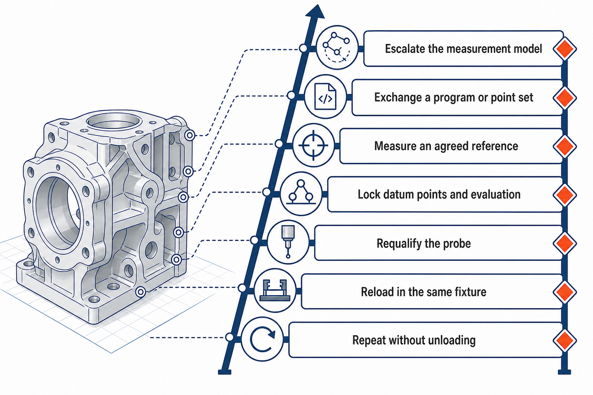
Use one controlled part and change one variable per rung so every repeat answers a specific question. Retain the evidence used to establish the status quo: the original values, setup, system state, inspection environment, inspection process, program revision, product condition, measurement accuracy statement, inspection data, and inspection reports where available.
- 1. Repeat without unloading. Same part, program, alignment, stylus, and fixture; this checks immediate repeat behavior.
- 2. Reload in the same fixture. A shift after loading points toward seating, cleanliness, orientation, or restraint.
- 3. Requalify the probe. Keep the program fixed and test whether qualification or stylus state changed the result.
- 4. Lock datum points and evaluation. Use the same controlled definition on both systems before judging numerical agreement.
- 5. Exchange a compatible program or point set. Separate hardware behavior from program and software differences where interfaces allow.
- 6. Measure an agreed reference. Use a calibrated artifact or suitable reference feature to test a focused hypothesis.
- 7. Escalate the measurement model. Review uncertainty, correlation, MSA evidence, software settings, and longer-term stability.
Repeated measurements may give a false sense of security about a stable process.
Treat two CMM reports as not yet equivalent until the part state, coordinate system, contact strategy, evaluation method, uncertainty, and decision rule are reconciled.
NIST warns that processes may drift, hysteresis may occur, and variability may increase over time. A probe error may make a process appear stable when it isn’t.
Do not force closure
Matching reruns narrow the suspect list, but they do not automatically clear long-term stability, correlated uncertainty, thermal history, or direction-dependent bias.
Matching reruns narrow the suspect list, but they do not automatically clear long-term stability, correlated uncertainty, thermal history, or direction-dependent bias.
Apply the CMM Report Equivalence Lock Before Comparing Numbers
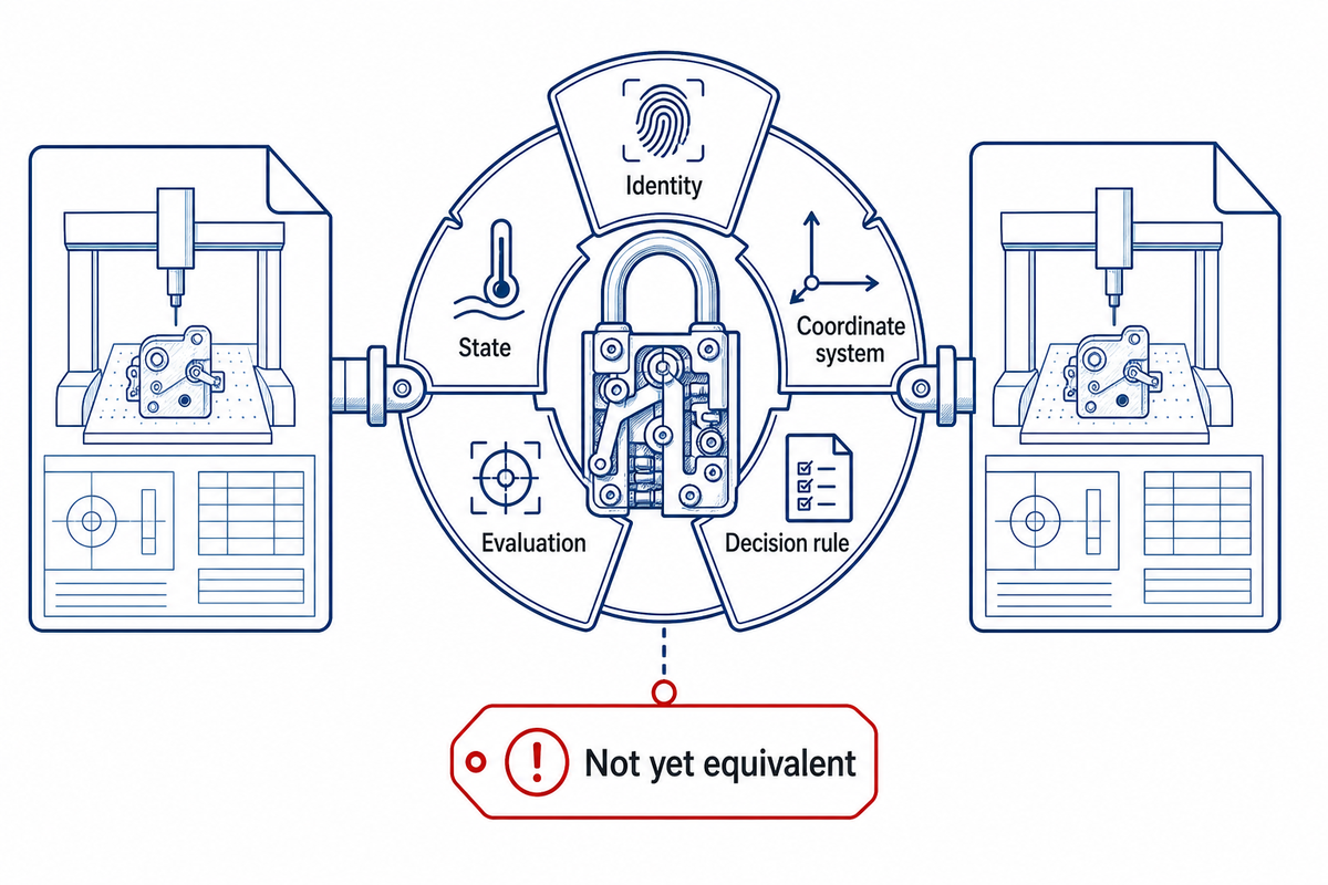
A reported value is not ready for comparison until it passes the CMM Report Equivalence Lock, a controlled checklist. A CMM inspection report may show a different value, but the values are ready for comparison only when the evidence supports equivalent measurement conditions. A CMM report can help resolve a supplier disagreement only after that equivalence check is complete.
| Lock category | Required evidence | Status |
|---|---|---|
| Identity | Same part, lot, revision, feature, units, and requirement | Matched / unresolved |
| State | Temperature, processing, surface, cleaning, fixture, and restraint | Matched / unresolved |
| Coordinate system | Datums, points, constraints, origin, rotations, and any best fit | Matched / unresolved |
| Contact and sampling | Stylus, qualification, approach, point map, scan, and boundaries | Matched / unresolved |
| Evaluation | Fit, filter, exclusions, projection, compensation, software, rounding | Matched / unresolved |
| Program and data | Program revision, software version, raw data, and change history | Matched / unresolved |
| Metrological basis | Verification, traceability, uncertainty, decision rule | Matched / unresolved |
| Correlation | Shared references, common corrections, programs, and environmental inputs | Identified / unresolved |
| Disposition | Rounding, guard band, reviewer, approval route, and report status | Matched / unresolved |
Illustrative arithmetic only
If one report shows 25.004 mm and another shows 25.009 mm, the difference is 0.005 mm. Even against an illustrative 25.000 mm nominal with a ±0.010 mm tolerance, that calculation does not establish acceptability until both results are comparison-ready and their uncertainty relationship is understood.
If one report shows 25.004 mm and another shows 25.009 mm, the difference is 0.005 mm. Even against an illustrative 25.000 mm nominal with a ±0.010 mm tolerance, that calculation does not establish acceptability until both results are comparison-ready and their uncertainty relationship is understood.
| Comparison field | Report A | Report B | Why it matters |
|---|---|---|---|
| Nominal diameter | 25.000 mm | 25.000 mm | The requirement appears aligned. |
| Drawing tolerance | ±0.010 mm | ±0.010 mm | Matching limits do not prove matching methods. |
| Reported result | 25.004 mm | 25.009 mm | The visible difference is 0.005 mm. |
| Part temperature | 20.1 °C | 21.0 °C | Part state is not equivalent. |
| Stylus tip | 3 mm | 5 mm | Contact geometry can differ. |
| Stylus extension | 80 mm | 120 mm | Deflection and access can differ. |
| Evaluated length | 50 mm | 40 mm | The sampled feature region differs. |
| Point count | 12 points | 60 points | Distribution still needs review. |
| Expanded uncertainty | ±0.004 mm | ±0.006 mm | The decision evidence differs. |
| Display increment | 0.001 mm | 0.001 mm | Equal resolution is not equal uncertainty. |
| Stabilization record | 2 hr | 4 hr | Elapsed time alone does not prove equilibrium. |
The example gives the evaluator a structured means to reach the conclusion of “not yet equivalent.” The conclusion shouldn’t be that 25.004 mm or 25.009 mm is the correct result.
Correlated uncertainties may exist if program or environment corrections share references, so the uncertainty of the difference may require covariance terms. Such a case may require consideration of covariance, while this example deliberately holds the drawing values constant and changes several measurement conditions.
Output label
Use “comparison-ready” only when every critical lock is closed. Otherwise, write “not yet equivalent” and identify the missing field instead of declaring one CMM wrong.
Use “comparison-ready” only when every critical lock is closed. Otherwise, write “not yet equivalent” and identify the missing field instead of declaring one CMM wrong.
Build a Discrepancy Handoff Pack for the Supplier or Lab
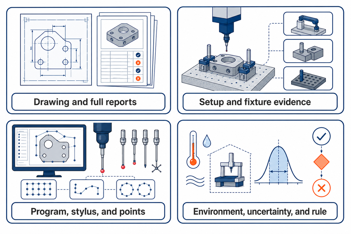
An effective escalation gives the supplier or laboratory enough controlled evidence to reproduce the disputed condition. Cropped screenshots typically result in an interpretation cycle. Providing the drawing, full reports, method settings, setup evidence, and decision basis turns the disagreement into a testable technical question.
Discrepancy Handoff Pack
- Controlled drawing and model revision
- Part, lot, and process-stage identity
- Both complete, unedited reports
- Marked disputed characteristics
- Setup and fixture photographs
- Program and alignment identifiers
- Stylus build and qualification record
- Point, scan, filter, and fit settings
- Environmental and part-state record
- Calibration or verification status
- Uncertainty statement and basis
- Agreed conformity decision rule
上海真灵五金有限公司 manufactures non-standard metal components from customer drawings or samples, but no generic company statement can establish the correct method for an individual feature. Use Zhenling’s metrology and inspection resource to align the drawing, inspection method, and report expectations during quotation or technical review.
Send the disputed characteristic, not just the difference
Attach the drawing revision, both complete reports, and the setup or method fields already confirmed. That gives the technical team a reproducible starting point.
Frequently Asked Questions
The focus of CMM resolution activities should be shifted from determining which machine is correct to determining which factor has varied. Examples provided here take measurement-system variability into consideration and avoid assigning a universal accuracy percentage, point count, stabilization time, tolerance, or acceptance limit.
Can two calibrated CMMs give different results?
Yes. Calibration does not make two complete inspection procedures identical, because part state, datum alignment, sampling, software, uncertainty, and decision rules still influence the reported value.
The reported value also depends on part state, fixture, datum alignment, stylus, sampled points, software evaluation, task-specific uncertainty, and decision rule. Confirm that both procedures measure the same characteristic before judging whether the numerical difference is important. If the conclusions conflict, preserve both setups and close the equivalence lock before recalibrating or averaging anything.
What is a 3-2-1 alignment in CMM inspection?
Datum alignment through primary, secondary, and tertiary relationships is a common way to constrain six degrees of freedom, creating a coordinate frame that depends on the selected features and constraint order.
The actual implementation must follow the drawing and approved procedure. Changing points, feature construction, constraint order, or datum realization can move the coordinate system, and a 3-2-1 setup is not automatically interchangeable with a best-fit alignment. Save the measured datum features and constraint sequence so another reviewer can reproduce the frame.
How should two different CMM results be investigated?
Start with one controlled part and repeat without unloading it, then change one variable per rung while preserving the setup, program, environment, and raw result evidence.
Then reload it, requalify the probe, lock the same datum points and evaluation rules, and change only one variable per rerun. Preserve each result and the environmental record; a change after reloading suggests a different mechanism from a stable offset between systems. If the offset persists, exchange a compatible program or controlled point set, measure an agreed reference, compare uncertainty and correlation, and document what each rung held fixed before changing the next variable.
Does taking more CMM points always improve accuracy?
No. Distribution and evaluation matter as much as the count, since a dense but biased pattern still fails to capture form or gives the wrong surface region too much weight.
A dense but biased pattern can still miss relevant form or overrepresent one region. Point placement, feature boundary, scanning behavior, filtering, and fitting rule must match the measurand.
Why can a micrometer and CMM disagree?
A micrometer and CMM may contact different locations and evaluate different geometric quantities, because a micrometer samples local contact while CMM software may reconstruct an ideal feature from many points.
A two-point hand tool can be useful for a local size check, while a CMM may reconstruct an ideal feature from many points in a coordinate system. Compare contact geometry, force, alignment, temperature, evaluation method, and uncertainty before deciding which result controls disposition.
What difference between CMMs is acceptable?
There is no universal percentage or millimeter value.
First establish equivalent measurands and procedures, then evaluate the difference against task-specific uncertainty and the agreed decision rule. A small numerical shift can matter near a tight limit, while a larger shift may not change a well-supported conclusion far from the boundary.
Turn a CMM Difference Into a Controlled Decision
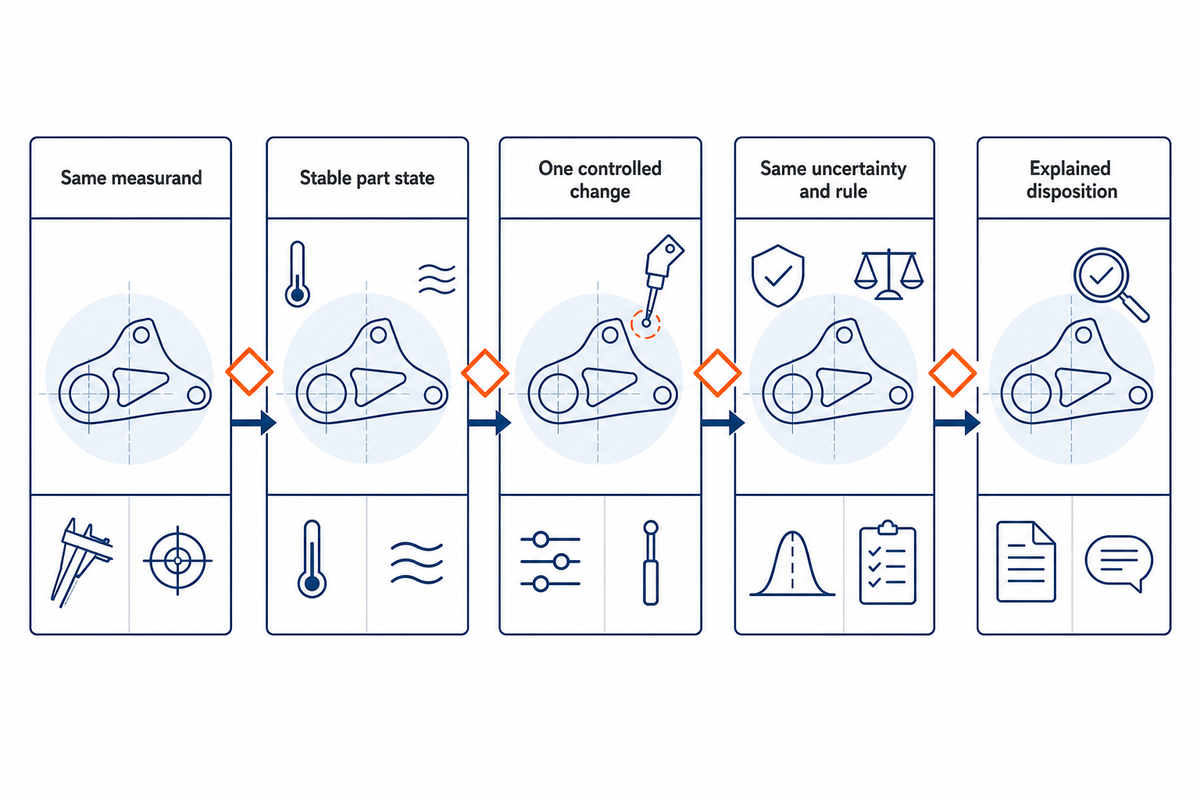
Resolve the CMM discrepancy in sequence: verify the same measurand, stabilize and document the part, hold the setup and method constant, change one layer at a time, then compare conclusions under the same uncertainty and decision rule. Variables should be changed one at a time. Comparisons should be made under the same uncertainty and decision rule so the sequence produces evidence instead of another unexplained repeat. This provides evidence that settles the dispute; repeating the same CMM process without altering the measurement system conditions results in an unexplained discrepancy.
The final measurement checkpointDo not close the investigation because two reruns match. Close it when the critical method fields are equivalent, the remaining difference is metrologically explained, and the disposition follows the agreed rule.
Before production release of a custom-machined component, provide the controlled drawing, critical characteristics, expected report format, and any customer-specific inspection requirements.
This ensures that the manufacturer and customer have defined what will be measured and the standard for evaluating the outcome.
References & Sources
- NIST, Traceability, Calibration and Measurement Uncertainty for CMMs
- NIST, Measurement Uncertainty Considerations for Coordinate Measuring Machines
- NIST, Dimensional Metrology Algorithm Testing
- ISO 1:2022, Standard Reference Temperature
- ISO 15530-3:2011, Experimental Technique for Task-Specific CMM Uncertainty
- ISO 14253-1:2017, Decision Rules for Verifying Conformity
- ASME B89.7.3.1, Decision Rules for Conformance
- NIST/SEMATECH, Repeatability and Long-Term Measurement Effects
- NIST, Direction-Dependent Touch-Trigger Probe Error
- JCGM VIM, Measurement Uncertainty and Covariance
- International Journal of Metrology and Quality Engineering, CMM Point Layout Study
Sources accessed September 29, 2026. Public catalogue pages identify scope; applicable editions and contract requirements should be confirmed for each project.